check LEXUS SC300 1991 Service Repair Manual
[x] Cancel search | Manufacturer: LEXUS, Model Year: 1991, Model line: SC300, Model: LEXUS SC300 1991Pages: 4087, PDF Size: 75.75 MB
Page 3994 of 4087
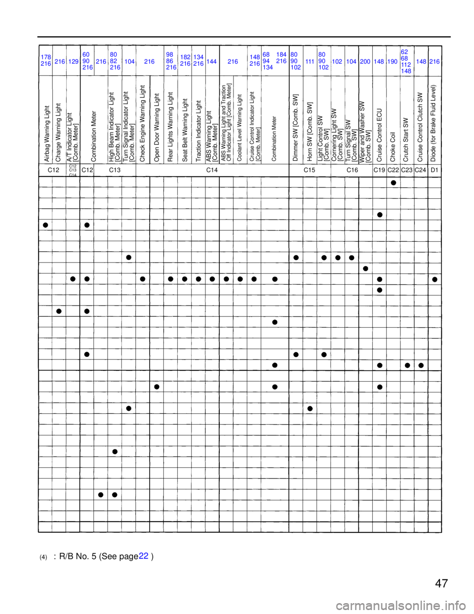
47
216182
216
178
216
129 104 144 10260
90
216 62
68
11 2
148
104
111 200 148 148 190
D1
C16 C24
C15 C19 C23 C22
C12
C13
C14C14
C13
C12
Airbag W arning Light
Charge Warning Light
Dimmer SW [Comb. SW]Cruise Control Indicator Light
[Comb. Meter]A/T Indicator Light
[Comb. Meter]
Combination Meter
Rear Lights Warning Light Turn Signal Indicator Light
[Comb. Meter] High Beam Indicator Light
[Comb. Meter]
Check Engine Warning Light
Open Door Warning Light
Traction Indicator Light
ABS Warning Light
[Comb. Meter] Seat Belt Warning LightABS Warning Light and T raction
Off Indicator Light [Comb. Meter]
Coolant Level Warning LightCruise Control ECU Turn Signal SW
[Comb. SW]
Wiper and Washer SW
[Comb. SW]
Choke Coil
Crutch Start SW
Cruise Control Clutch SW
Diode (for Brake Fluid Level)Light Control SW
[Comb. SW] Horn SW [Comb. SW]Combination MeterCornering Light SW
[Comb. SW]
C12 80
82
216
216 216 98
86
216134
216
216 216 184
216
80
90
102 80
90
102
68
94
134
148
216
(4)
: R/B No. 5 (See page ) 22
WhereEverybodyKnowsYourName
Page 4054 of 4087

178
SRS AIRBAG
The airbag system has connectors which possess the functions described belo\
w:1. AIRBAG ACTIVATION PREVENTION MECHANISMEach connector contains a short spring plate. When the
connector is disconnected, the short spring plate
automatically connects the power source and grounding
terminals of the squib to preclude a potential difference
between the terminals.
2. ELECTRICAL CONNECTION CHECK MECHANISMThis mechanism is designed to electrically check if
connectors are connected correctly and completely.
The electrical connection check mechanism is designed so
that the connection detection pin connects with the
diagnosis terminals when the connector housing lock is in
the locked condition.
WhereEverybodyKnowsYourName
Page 4056 of 4087
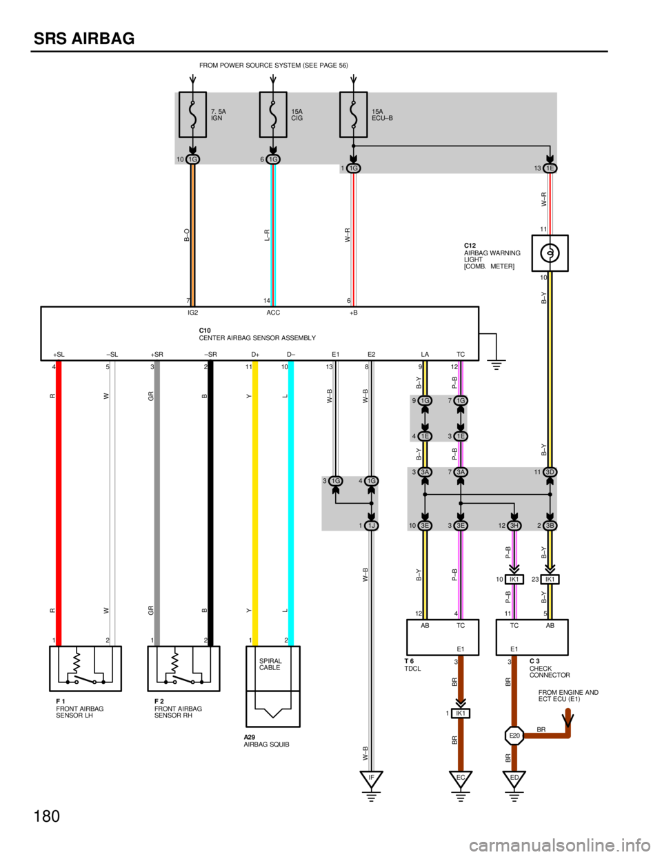
180
SRS AIRBAG
1G
10 1G 6
1G
11E 13
10 11
IK1
10 IK1 23
IK 1
1
4
+SL
5±SL
3+SR
2±SR
11D+
10D±
13E1
8E2
3E1
3E1
7
IG2 14
ACC 6
+B
12AB 4
TC 11
TC 5
AB
121212 7. 5A
IGN
15A
CIG 15A
ECU±B
FROM ENGINE AND
ECT ECU(
E1 )
CHECK
CONNECTOR
TDCL
FRONT AIRBAG
SENSOR LH FRONT A I RBA G
SENSOR RH
AIRBAG SQUIBSPIRAL
CA BLE
CENTER AIRBAG SENSOR ASSEMBLY
BR
W±B W±BL
Y B
GR
WR
L
Y
B
GR
WR
BR W±B
BR BR BR B±Y P±BP±B
B±Y
P±B
B±Y B±Y W±RW±R
L±R
B±O
FROM POWER SOURCE SYSTEM
(
SEE PAGE 56 )
AIRBA G WA RNING
LIGHT
[COMB. METER]
C10
F1 F2 A2 9 C3
T6 C12
E2 0
1G
9 912
IF ED 1G
7
EC
LA TC
1E
41E 3
3B
2
3H
12
3E
3
3E
10
1J
1 3A
3
1G
4
1G
3 3A
73D 11
B±Y
P±B
B±Y
P±B
B±Y
W±B
WhereEverybodyKnowsYourName
Page 4060 of 4087
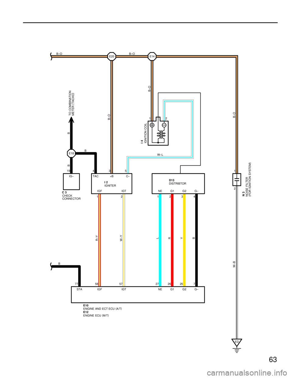
63
E18E14
E20
2 1
ED
W± L
B
B±O
B
W± B B±OB±O
B±O
BB
B± O
TO COMBINATION
METER
(
TACHO )12
DISTRIBTOR
IGNITION COIL
I4
D13
IG± TAC +B
IGF IGT C±
IGNITER
CHECK
CONNECTOR
C3 I2
435
19
12
STA IGF IGT
77 58 57
ENGINE AND ECT ECU (
A/T )
E10
NOISE FILTER
(
FOR IGNITION SYSTEM )
N31234
27 26 25 7 NE G1 G2 G± NE G1 G2 G±
L
R Y
B
W±Y
R±Y
ENGINE ECU
(
M/T )
E12
WhereEverybodyKnowsYourName
Page 4076 of 4087
10
TROUBLESHOOTING
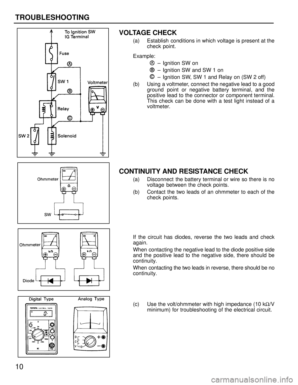
VOLTAGE CHECK
(a) Establish conditions in which voltage is present at thecheck point.
Example: ± Ignition SW on
± Ignition SW and SW 1 on
± Ignition SW, SW 1 and Relay on (SW 2 off)
(b) Using a voltmeter, connect the negative lead to a good ground point or negative battery terminal, and the
positive lead to the connector or component terminal.
This check can be done with a test light instead of a
voltmeter.
CONTINUITY AND RESISTANCE CHECK
(a) Disconnect the battery terminal or wire so there is novoltage between the check points.
(b) Contact the two leads of an ohmmeter to each of the check points.
If the circuit has diodes, reverse the two leads and check
again.
When contacting the negative lead to the diode positive side
and the positive lead to the negative side, there should be
continuity.
When contacting the two leads in reverse, there should be no
continuity.
(c) Use the volt/ohmmeter with high impedance (10 k W/V
minimum) for troubleshooting of the electrical circuit.
WhereEverybodyKnowsYourName
Page 4077 of 4087
11
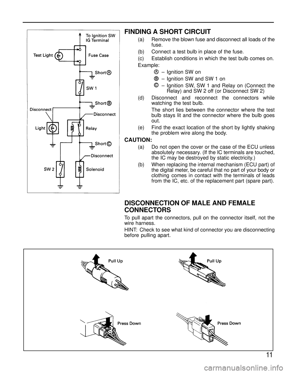
FINDING A SHORT CIRCUIT
(a) Remove the blown fuse and disconnect all loads of thefuse.
(b) Connect a test bulb in place of the fuse.
(c) Establish conditions in which the test bulb comes on.
Example: ± Ignition SW on
± Ignition SW and SW 1 on
± Ignition SW, SW 1 and Relay on (Connect theRelay) and SW 2 off (or Disconnect SW 2)
(d) Disconnect and reconnect the connectors while watching the test bulb.
The short lies between the connector where the test
bulb stays lit and the connector where the bulb goes
out.
(e) Find the exact location of the short by lightly shaking the problem wire along the body.
CAUTION:
(a) Do not open the cover or the case of the ECU unlessabsolutely necessary. (If the IC terminals are touched,
the IC may be destroyed by static electricity.)
(b) When replacing the internal mechanism (ECU part) of the digital meter, be careful that no part of your body or
clothing comes in contact with the terminals of leads
from the IC, etc. of the replacement part (spare part).
DISCONNECTION OF MALE AND FEMALE
CONNECTORS
To pull apart the connectors, pull on the connector itself, not the
wire harness.
HINT: Check to see what kind of connector you are disconnecting
before pulling apart.
WhereEverybodyKnowsYourName
Page 4078 of 4087
12
TROUBLESHOOTING
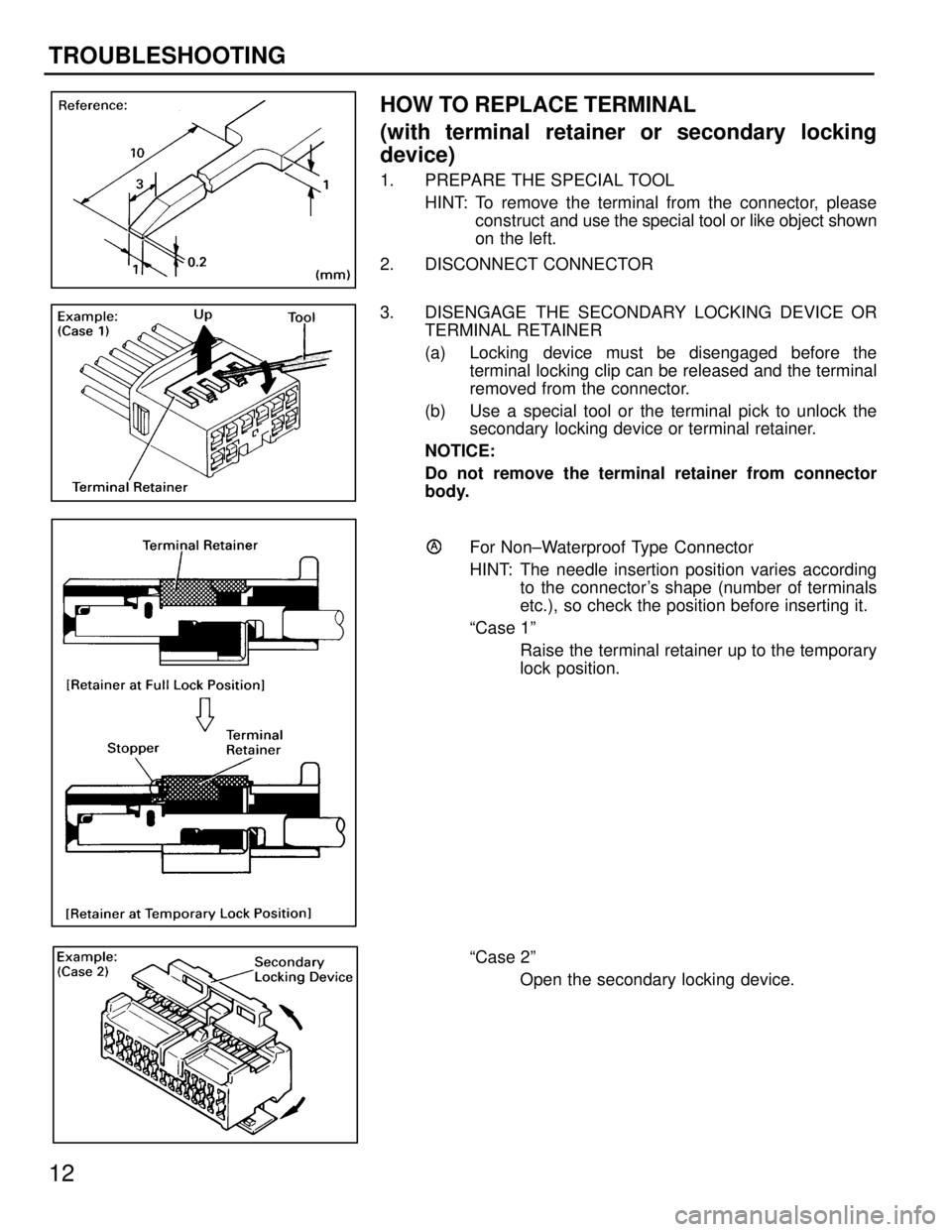
HOW TO REPLACE TERMINAL
(with terminal retainer or secondary locking
device)
1. PREPARE THE SPECIAL TOOLHINT: To remove the terminal from the connector, please construct and use the special tool or like object shown
on the left.
2. DISCONNECT CONNECTOR
3. DISENGAGE THE SECONDARY LOCKING DEVICE OR TERMINAL RETAINER
(a) Locking device must be disengaged before theterminal locking clip can be released and the terminal
removed from the connector.
(b) Use a special tool or the terminal pick to unlock the secondary locking device or terminal retainer.
NOTICE:
Do not remove the terminal retainer from connector
body.
For Non±Waterproof Type Connector
HINT: The needle insertion position varies according to the connector's shape (number of terminals
etc.), so check the position before inserting it.
ªCase 1º Raise the terminal retainer up to the temporary
lock position.
ªCase 2º Open the secondary locking device.
WhereEverybodyKnowsYourName
Page 4079 of 4087
13
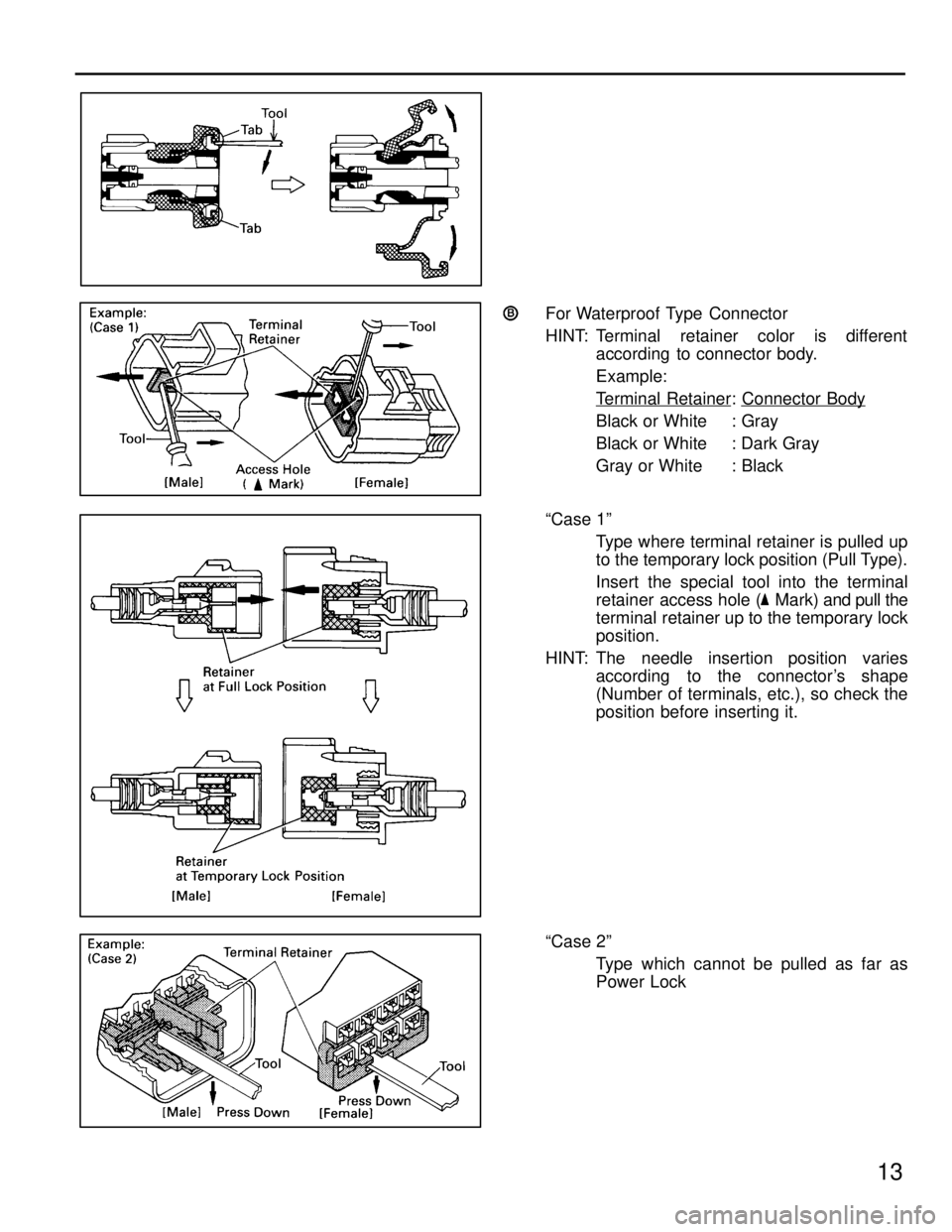
For Waterproof Type Connector
HINT: Terminal retainer color is differentaccording to connector body.
Example:
Terminal Retainer
: Connector Body
Black or White : Gray
Black or White : Dark Gray
Gray or White : Black
ªCase 1º Type where terminal retainer is pulled up
to the temporary lock position (Pull Type).
Insert the special tool into the terminal
retainer access hole ( Mark) and pull the
terminal retainer up to the temporary lock
position.
HINT: The needle insertion position varies according to the connector's shape
(Number of terminals, etc.), so check the
position before inserting it.
ªCase 2º Type which cannot be pulled as far as
Power Lock
WhereEverybodyKnowsYourName
Page 4081 of 4087
15
ABBREVIATIONS
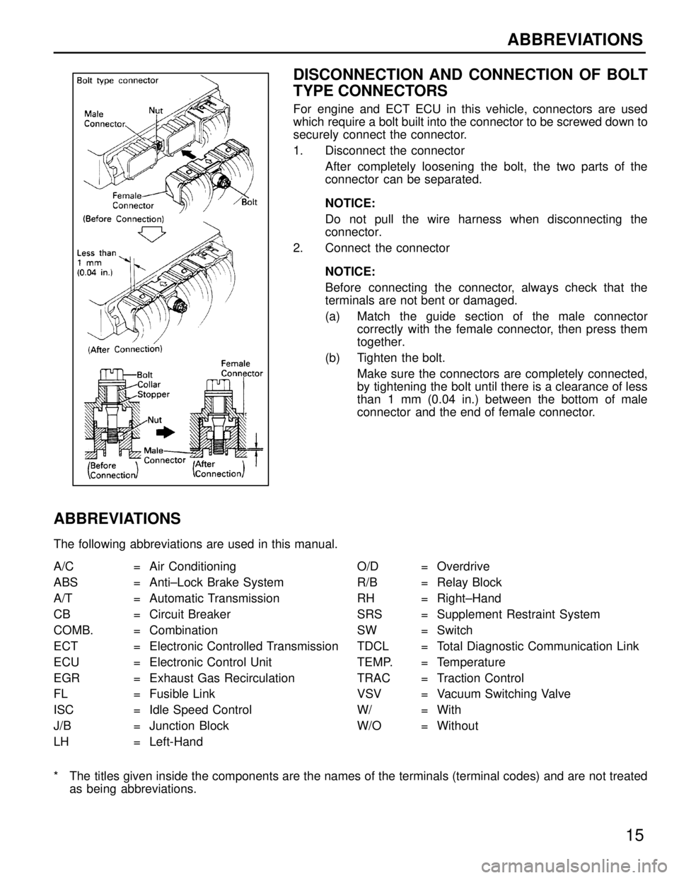
DISCONNECTION AND CONNECTION OF BOLT
TYPE CONNECTORS
For engine and ECT ECU in this vehicle, connectors are used
which require a bolt built into the connector to be screwed down to
securely connect the connector.
1. Disconnect the connectorAfter completely loosening the bolt, the two parts of the
connector can be separated.
NOTICE:
Do not pull the wire harness when disconnecting the
connector.
2. Connect the connector
NOTICE:
Before connecting the connector, always check that the
terminals are not bent or damaged.
(a) Match the guide section of the male connectorcorrectly with the female connector, then press them
together.
(b) Tighten the bolt. Make sure the connectors are completely connected,
by tightening the bolt until there is a clearance of less
than 1 mm (0.04 in.) between the bottom of male
connector and the end of female connector.
ABBREVIATIONS
The following abbreviations are used in this manual.
A/C = Air Conditioning O/D = Overdrive
ABS = Anti±Lock Brake System R/B = Relay Block
A/T = Automatic Transmission RH = Right±Hand
CB = Circuit Breaker SRS = Supplement Restraint System
COMB. = Combination SW = Switch
ECT = Electronic Controlled Transmission TDCL = Total Diagnostic Communication Link
ECU = Electronic Control Unit TEMP. = Temperature
EGR = Exhaust Gas Recirculation TRAC = Traction Control
FL = Fusible Link VSV = Vacuum Switching Valve
ISC = Idle Speed Control W/ = With
J/B = Junction Block W/O = Without
LH = Left-Hand
* The titles given inside the components are the names of the terminals (ter\
minal codes) and are not treatedas being abbreviations.
WhereEverybodyKnowsYourName