sensor LEXUS SC300 1991 Service Repair Manual
[x] Cancel search | Manufacturer: LEXUS, Model Year: 1991, Model line: SC300, Model: LEXUS SC300 1991Pages: 4087, PDF Size: 75.75 MB
Page 2109 of 4087
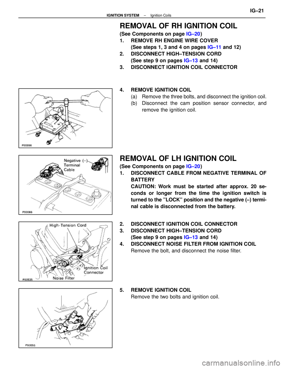
REMOVAL OF RH IGNITION COIL
(See Components on page IG±20)
1. REMOVE RH ENGINE WIRE COVER (See steps 1, 3 and 4 on pages IG±11 and 12)
2. DISCONNECT HIGH±TENSION CORD (See step 9 on pages IG±13 and 14)
3. DISCONNECT IGNITION COIL CONNECTOR
4. REMOVE IGNITION COIL (a) Remove the three bolts, and disconnect the ignition coil.
(b) Disconnect the cam position sensor connector, and
remove the ignition coil.
REMOVAL OF LH IGNITION COIL
(See Components on page IG±20)
1. DISCONNECT CABLE FROM NEGATIVE TERMINAL OF BATTERY
CAUTION: Work must be started after approx. 20 se-
conds or longer from the time the ignition switch is
turned to the ºLOCKº position and the negative (±) termi-
nal cable is disconnected from the battery.
2. DISCONNECT IGNITION COIL CONNECTOR
3. DISCONNECT HIGH±TENSION CORD (See step 9 on pages IG±13 and 14)
4. DISCONNECT NOISE FILTER FROM IGNITION COIL Remove the bolt, and disconnect the noise filter.
5. REMOVE IGNITION COIL Remove the two bolts and ignition coil.
±
IGNITION SYSTEM Ignition CoilsIG±21
WhereEverybodyKnowsYourName
Page 2110 of 4087
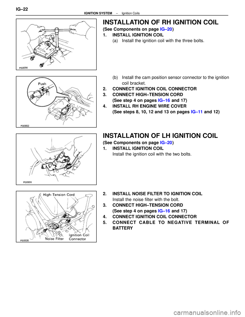
INSTALLATION OF RH IGNITION COIL
(See Components on page IG±20)
1. INSTALL IGNITION COIL (a) Install the ignition coil with the three bolts.
(b) Install the cam position sensor connector to the ignition
coil bracket.
2. CONNECT IGNITION COIL CONNECTOR
3. CONNECT HIGH±TENSION CORD
(See step 4 on pages IG±16 and 17)
4. INSTALL RH ENGINE WIRE COVER (See steps 8, 10, 12 and 13 on pages IG±11 and 12)
INSTALLATION OF LH IGNITION COIL
(See Components on page IG±20)
1. INSTALL IGNITION COIL Install the ignition coil with the two bolts.
2. INSTALL NOISE FILTER TO IGNITION COIL Install the noise filter with the bolt.
3. CONNECT HIGH±TENSION CORD
(See step 4 on pages IG±16 and 17)
4. CONNECT IGNITION COIL CONNECTOR
5. CONNECT CABLE TO NEGATIVE TERMINAL OF BATTERY
IG±22
±
IGNITION SYSTEM Ignition Coils
WhereEverybodyKnowsYourName
Page 2112 of 4087
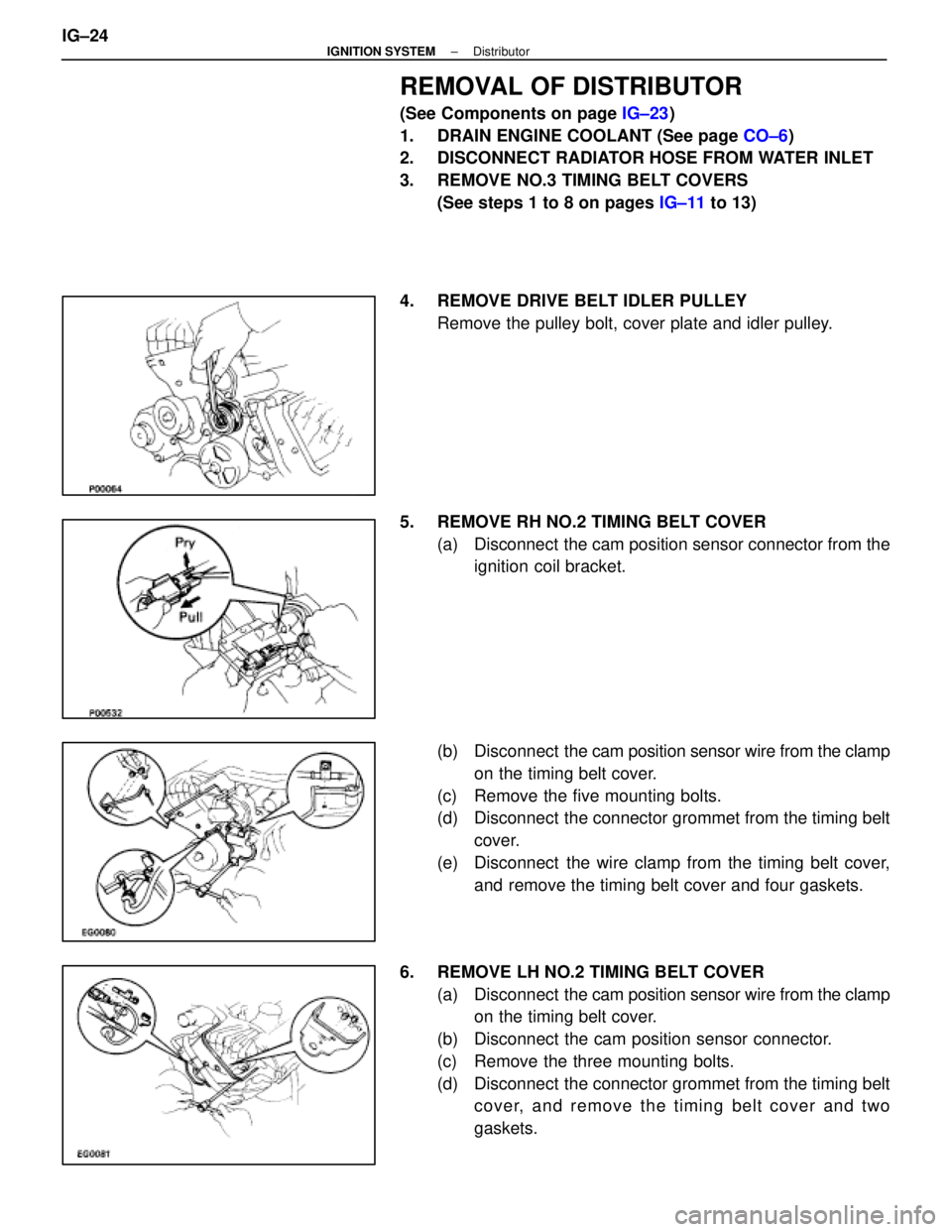
REMOVAL OF DISTRIBUTOR
(See Components on page IG±23)
1. DRAIN ENGINE COOLANT (See page CO±6)
2. DISCONNECT RADIATOR HOSE FROM WATER INLET
3. REMOVE NO.3 TIMING BELT COVERS
(See steps 1 to 8 on pages IG±11 to 13)
4. REMOVE DRIVE BELT IDLER PULLEY Remove the pulley bolt, cover plate and idler pulley.
5. REMOVE RH NO.2 TIMING BELT COVER (a) Disconnect the cam position sensor connector from theignition coil bracket.
(b) Disconnect the cam position sensor wire from the clamp
on the timing belt cover.
(c) Remove the five mounting bolts.
(d) Disconnect the connector grommet from the timing belt cover.
(e) Disconnect the wire clamp from the timing belt cover, and remove the timing belt cover and four gaskets.
6. REMOVE LH NO.2 TIMING BELT COVER (a) Disconnect the cam position sensor wire from the clamp
on the timing belt cover.
(b) Disconnect the cam position sensor connector.
(c) Remove the three mounting bolts.
(d) Disconnect the connector grommet from the timing belt cover, and remove the timing belt cover and two
gaskets.
IG±24
±
IGNITION SYSTEM Distributor
WhereEverybodyKnowsYourName
Page 2113 of 4087
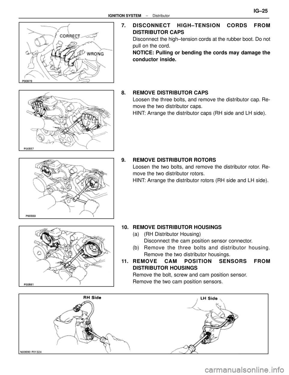
7. DISCONNECT HIGH±TENSION CORDS FROMDISTRIBUTOR CAPS
Disconnect the high±tension cords at the rubber boot. Do not
pull on the cord.
NOTICE: Pulling or bending the cords may damage the
conductor inside.
8. REMOVE DISTRIBUTOR CAPS Loosen the three bolts, and remove the distributor cap. Re-
move the two distributor caps.
HINT: Arrange the distributor caps (RH side and LH side).
9. REMOVE DISTRIBUTOR ROTORS Loosen the two bolts, and remove the distributor rotor. Re-
move the two distributor rotors.
HINT: Arrange the distributor rotors (RH side and LH side).
10. REMOVE DISTRIBUTOR HOUSINGS (a) (RH Distributor Housing)Disconnect the cam position sensor connector.
(b) Re mo ve th e th re e bo lts an d distrib u to r ho u sin g . Remove the two distributor housings.
11. REMOVE CAM POSITION SENSORS FROM DISTRIBUTOR HOUSINGS
Remove the bolt, screw and cam position sensor.
Remove the two cam position sensors.
±
IGNITION SYSTEM DistributorIG±25
WhereEverybodyKnowsYourName
Page 2114 of 4087
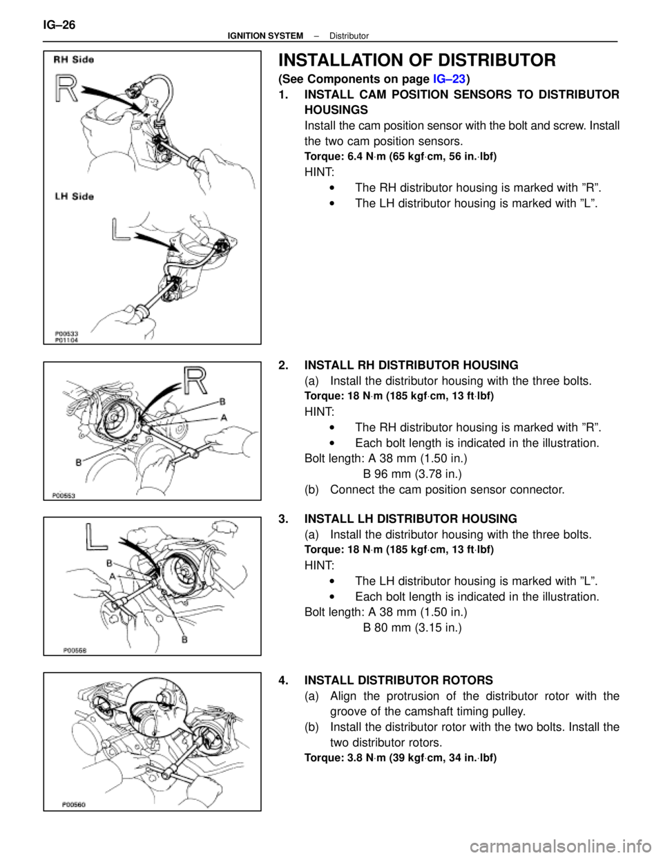
INSTALLATION OF DISTRIBUTOR
(See Components on page IG±23)
1. INSTALL CAM POSITION SENSORS TO DISTRIBUTOR HOUSINGS
Install the cam position sensor with the bolt and screw. Install
the two cam position sensors.
Torque: 6.4 N Vm (65 kgf Vcm, 56 in. Vlbf)
HINT:
w The RH distributor housing is marked with ºRº.
w The LH distributor housing is marked with ºLº.
2. INSTALL RH DISTRIBUTOR HOUSING (a) Install the distributor housing with the three bolts.
Torque: 18 N Vm (185 kgf Vcm, 13 ft Vlbf)
HINT:
w The RH distributor housing is marked with ºRº.
w Each bolt length is indicated in the illustration.
Bolt length: A 38 mm (1.50 in.)
B 96 mm (3.78 in.)
(b) Connect the cam position sensor connector.
3. INSTALL LH DISTRIBUTOR HOUSING (a) Install the distributor housing with the three bolts.
Torque: 18 N Vm (185 kgf Vcm, 13 ft Vlbf)
HINT:
w The LH distributor housing is marked with ºLº.
w Each bolt length is indicated in the illustration.
Bolt length: A 38 mm (1.50 in.)
B 80 mm (3.15 in.)
4. INSTALL DISTRIBUTOR ROTORS (a) Align the protrusion of the distributor rotor with thegroove of the camshaft timing pulley.
(b) Install the distributor rotor with the two bolts. Install the two distributor rotors.
Torque: 3.8 N Vm (39 kgf Vcm, 34 in. Vlbf)
IG±26±
IGNITION SYSTEM Distributor
WhereEverybodyKnowsYourName
Page 2115 of 4087
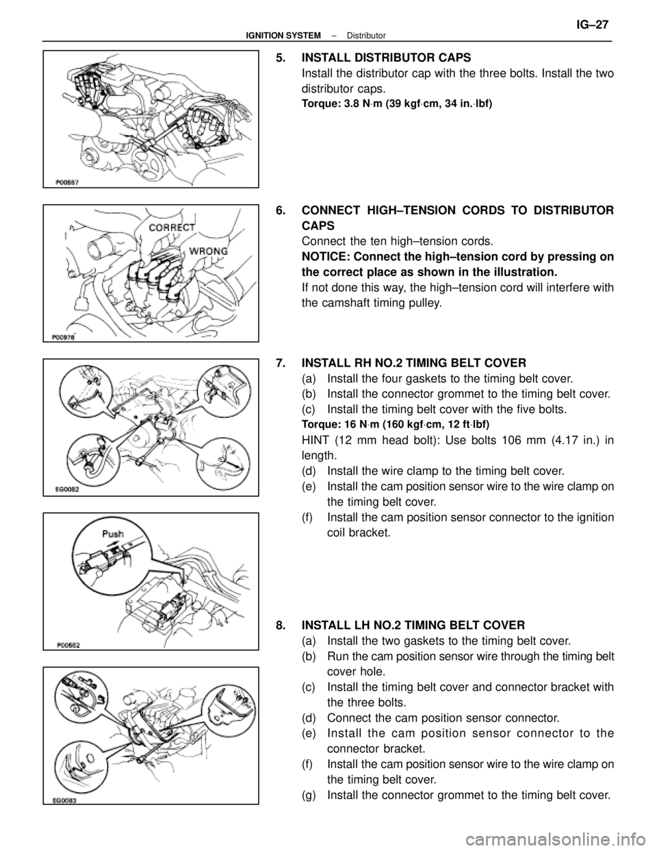
5. INSTALL DISTRIBUTOR CAPSInstall the distributor cap with the three bolts. Install the two
distributor caps.
Torque: 3.8 N Vm (39 kgf Vcm, 34 in. Vlbf)
6. CONNECT HIGH±TENSION CORDS TO DISTRIBUTOR
CAPS
Connect the ten high±tension cords.
NOTICE: Connect the high±tension cord by pressing on
the correct place as shown in the illustration.
If not done this way, the high±tension cord will interfere with
the camshaft timing pulley.
7. INSTALL RH NO.2 TIMING BELT COVER (a) Install the four gaskets to the timing belt cover.
(b) Install the connector grommet to the timing belt cover.
(c) Install the timing belt cover with the five bolts.
Torque: 16 N Vm (160 kgf Vcm, 12 ft Vlbf)
HINT (12 mm head bolt): Use bolts 106 mm (4.17 in.) in
length.
(d) Install the wire clamp to the timing belt cover.
(e) Install the cam position sensor wire to the wire clamp on
the timing belt cover.
(f) Install the cam position sensor connector to the ignition coil bracket.
8. INSTALL LH NO.2 TIMING BELT COVER (a) Install the two gaskets to the timing belt cover.
(b) Run the cam po sition sensor wire through the timing belt
cover hole.
(c) Install the timing belt cover and connector bracket with the three bolts.
(d) Connect the cam position sensor connector.
(e) In sta ll th e ca m po sitio n se n so r c onnector to the
connector bracket.
(f) Install the cam position sensor wire to the wire clamp on
the timing belt cover.
(g) Install the connector grommet to the timing belt cover.
±
IGNITION SYSTEM DistributorIG±27
WhereEverybodyKnowsYourName
Page 2117 of 4087
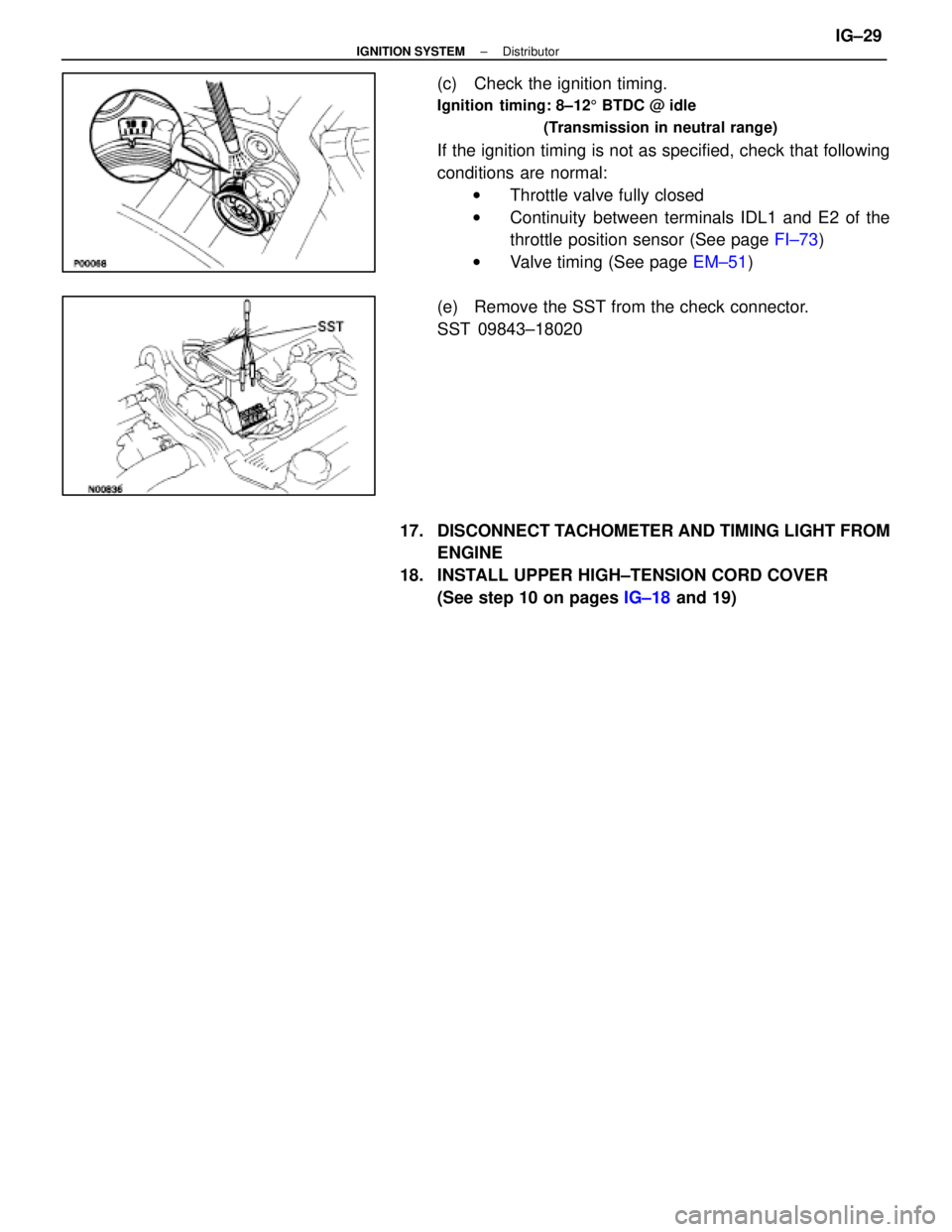
(c) Check the ignition timing.
Ignition timing: 8±125 BTDC @ idle
(Transmission in neutral range)
If the ignition timing is not as specified, check that following
conditions are normal: w Throttle valve fully closed
w Continuity between terminals IDL1 and E2 of the
throttle position sensor (See page FI±73)
w Valve timing (See page EM±51)
(e) Remove the SST from the check connector.
SST 09843±18020
17. DISCONNECT TACHOMETER AND TIMING LIGHT FROM ENGINE
18. INSTALL UPPER HIGH±TENSION CORD COVER (See step 10 on pages IG±18 and 19)
±
IGNITION SYSTEM DistributorIG±29
WhereEverybodyKnowsYourName
Page 2118 of 4087

SERVICE SPECIFICATIONS
SERVICE DATA
Oil pressureat idle speed29 kPa (0.3 kgf/cm, 4.3 psi) or more
at 3,000 rpm 294±539 kPa
(3.0±5.5 kgf/cm, 43±78 psi)
Oil pumpTip clearanceSTD0.310±0.490 mm0.0122±0.0193 in.
Limit 0.53 mm0.0209 in.
Body clearanceSTD 0.100±0.175 mm0.0039±0.0069 in.
Limit 0.20 mm0.0079 in.
Rotor clearanceSTD 0.030±0.090 mm0.0012±0.0035 in.
Limit0.12 mm0.0047 in.
TORQUE SPECIFICATIONS
Part tightenedN mkgf cmftVlbf
A/C compressor X Cylinder blockThrough bolt2626519
Bolt and nut 52530 38
Oil pressure switch X Cylinder
block14150 11
Oil drain plug X No.2 oil pan45450 33
Oil pump body cover X Oil pump
body10105 8
Plug X Oil pump body49500 36
Oil pump X Cylinder block21210 15
No.1 oil pan X Cylinder block12 mm head bolt21210 15
14 mm head bolt39400 29
Oil pan baffle plate X No.1 oil pan8.8 90 78 in.
Vlbf
Oil strainer X No.1 oil pan8.8 90 78 in. Vlbf
No.2 oil pan X No.1 oil pan8.8 90 78 in. Vlbf
Oil level sensor X No.1 oil pan5.4 5548 in. Vlbf
±
LUBRICATION SYSTEM Service SpecificationsLU±19
WhereEverybodyKnowsYourName
Page 2119 of 4087

SERVICE SPECIFICATIONS
SERVICE DATA
Oil pressureat idling29 kPa (0.3 kgf/cm2, 4.3 psi) or more
at 3,000 rpm 294±588 kPa
(3.0±6.0 kgf/cm2, 43±85 psi)
Oil pumpTip clearanceSTD0.110±0.240 mm0.0043±0.0094 in.
Limit 0.35 mm0.0138 in.
Side clearanceSTD 0.030±0.090 mm0.0012±0.0035 in.
Limit 0.15 mm0.0059 in.
Body clearanceSTD 0.100±0.175 mm0.0039±0.0069 in.
Limit0.30 mm0.0118 in.
TORQUE SPECIFICATIONS
Part tightenedNVmkgf Vcmft Vlbf
Oil oumo body cover X Oil pump body101058
Oil pump X Cylinder block12 mm head 16160 12
14 mm head 30310 22
Engine speed sensor X Oil pump6.465 56 in. Vlbf
Oil filter bracket X Oil pump18185 13
Oil strainer X Oil pump7.880 69 in. Vlbf
Oil strainer X Cylinder block7.880 69 in. Vlbf
No.2 oil pan X Cylinder block10 mm head 7.880 69 in. Vlbf
12 mm head 18185 13
Oil pan baffle plate X No.1 oil pan7.880 69 in. Vlbf
No.2 oil pan X No.1 oil pan7.880 69 in. Vlbf
No.2 oil pan X Cylinder block7.880 69 in. Vlbf
Oil level sensor X No.1 oil pan5.45548 in. Vlbf
LU±20±
LUBRICATION SYSTEM Service Specifications
WhereEverybodyKnowsYourName
Page 2130 of 4087
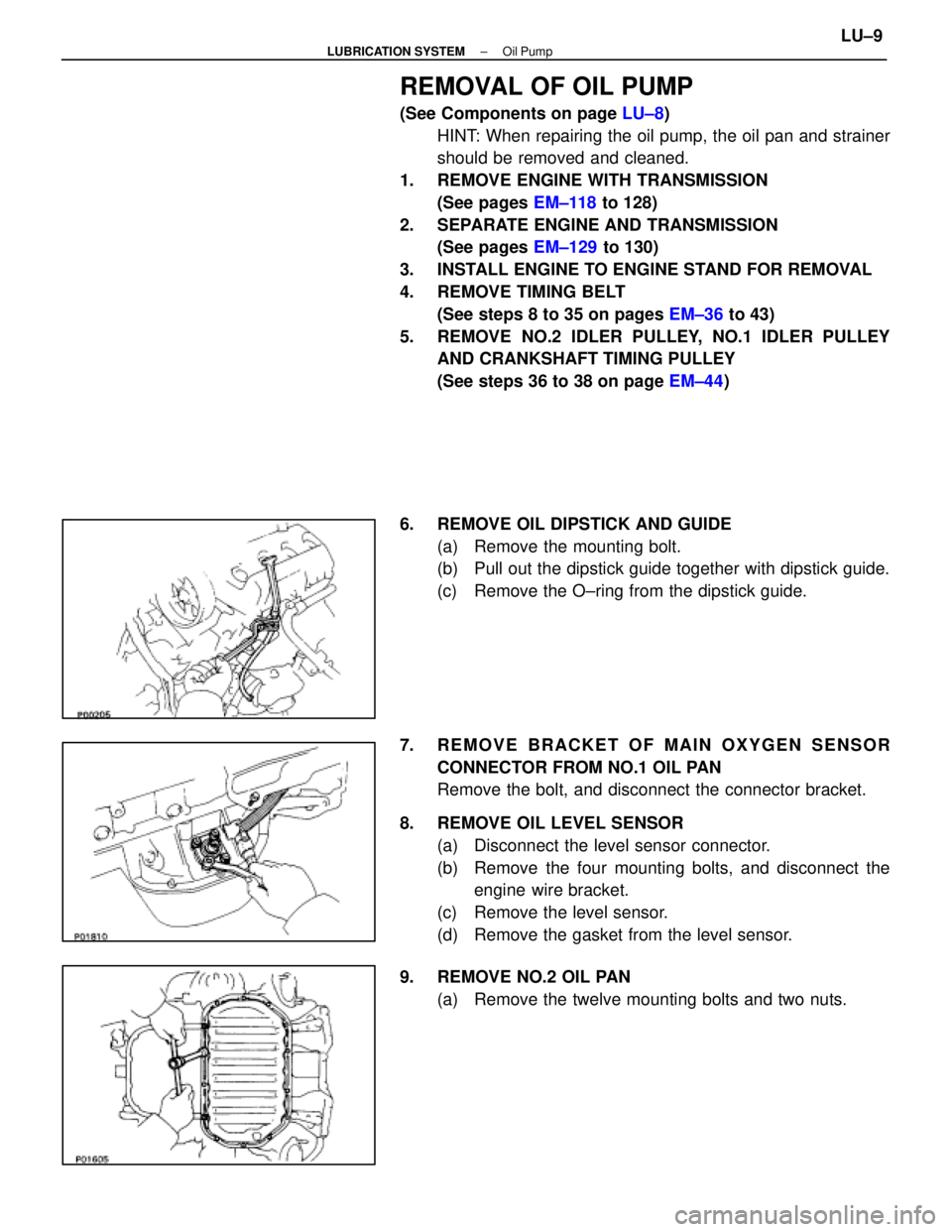
REMOVAL OF OIL PUMP
(See Components on page LU±8)
HINT: When repairing the oil pump, the oil pan and strainer
should be removed and cleaned.
1. REMOVE ENGINE WITH TRANSMISSION (See pages EM±118 to 128)
2. SEPARATE ENGINE AND TRANSMISSION (See pages EM±129 to 130)
3. INSTALL ENGINE TO ENGINE STAND FOR REMOVAL
4. REMOVE TIMING BELT (See steps 8 to 35 on pages EM±36 to 43)
5. REMOVE NO.2 IDLER PULLEY, NO.1 IDLER PULLEY AND CRANKSHAFT TIMING PULLEY
(See steps 36 to 38 on page EM±44)
6. REMOVE OIL DIPSTICK AND GUIDE (a) Remove the mounting bolt.
(b) Pull out the dipstick guide together with dipstick guide.
(c) Remove the O±ring from the dipstick guide.
7. REMOVE BRACKET OF MAIN OXYGEN SENSOR CONNECTOR FROM NO.1 OIL PAN
Remove the bolt, and disconnect the connector bracket.
8. REMOVE OIL LEVEL SENSOR (a) Disconnect the level sensor connector.
(b) Remove the four mounting bolts, and disconnect theengine wire bracket.
(c) Remove the level sensor.
(d) Remove the gasket from the level sensor.
9. REMOVE NO.2 OIL PAN (a) Remove the twelve mounting bolts and two nuts.
±
LUBRICATION SYSTEM Oil PumpLU±9
WhereEverybodyKnowsYourName