evap LEXUS SC400 1991 Service Repair Manual
[x] Cancel search | Manufacturer: LEXUS, Model Year: 1991, Model line: SC400, Model: LEXUS SC400 1991Pages: 4087, PDF Size: 75.75 MB
Page 3783 of 4087

AIR CONDITIONING EVAPORATOR ODOR ± AC001±97 September 12, 1997
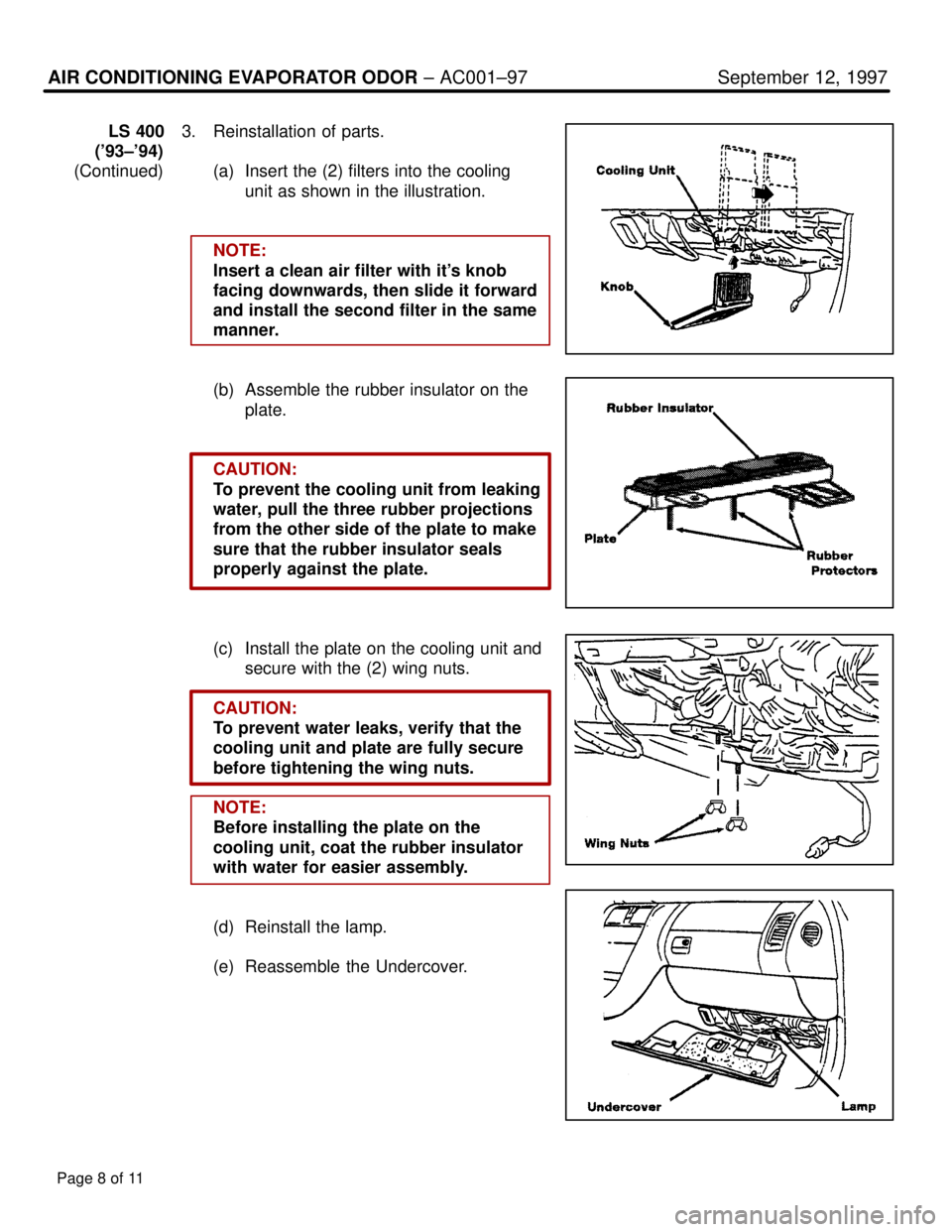
LS 4003. Reinstallation of parts.
('93±'94)
(Continued) (a) Insert the (2) filters into the cooling
unit as shown in the illustration.
NOTE:
Insert a clean air filter with it's knob
facing downwards, then slide it forward
and install the second filter in the same
manner.
(b) Assemble the rubber insulator on the plate.
CAUTION:
To prevent the cooling unit from leaking
water, pull the three rubber projections
from the other side of the plate to make
sure that the rubber insulator seals
properly against the plate.
(c) Install the plate on the cooling unit and secure with the (2) wing nuts.
CAUTION:
To prevent water leaks, verify that the
cooling unit and plate are fully secure
before tightening the wing nuts.
NOTE:
Before installing the plate on the
cooling unit, coat the rubber insulator
with water for easier assembly.
(d) Reinstall the lamp.
(e) Reassemble the Undercover.
Page 8 of 11
WhereEverybodyKnowsYourName
Page 3784 of 4087

Page 9 of 11
AIR CONDITIONING EVAPORATOR ODOR ± AC001±97 September 12, 1997
SC 3001. Removal of parts.
SC 400 (a) Remove two clips using the clip
remover then remove the undercover.
NOTE:
Pull down the clip areas (4 places) of
the Undercover to remove.
(b) Remove the (2) wing nuts and the plate on the bottom of the cooling unit.
CAUTION:
The plate and wing nuts will be reused.
(c) Remove the (2) filters from the cooling unit.
2. Clean the Evaporator � Follow the general procedures given on
page 2.
NOTE:
Location for the insertion of spray
nozzle is indicated by the red arrow
in the illustration.
WhereEverybodyKnowsYourName
Page 3785 of 4087

AIR CONDITIONING EVAPORATOR ODOR ± AC001±97 September 12, 1997
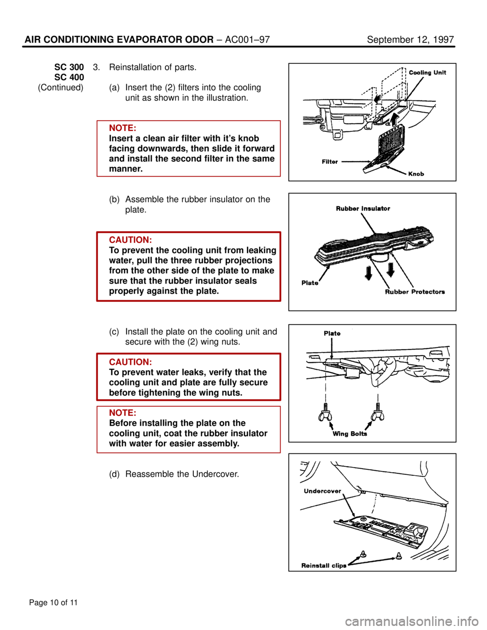
SC 3003. Reinstallation of parts.
SC 400
(Continued) (a) Insert the (2) filters into the cooling
unit as shown in the illustration.
NOTE:
Insert a clean air filter with it's knob
facing downwards, then slide it forward
and install the second filter in the same
manner.
(b) Assemble the rubber insulator on the plate.
CAUTION:
To prevent the cooling unit from leaking
water, pull the three rubber projections
from the other side of the plate to make
sure that the rubber insulator seals
properly against the plate.
(c) Install the plate on the cooling unit and secure with the (2) wing nuts.
CAUTION:
To prevent water leaks, verify that the
cooling unit and plate are fully secure
before tightening the wing nuts.
NOTE:
Before installing the plate on the
cooling unit, coat the rubber insulator
with water for easier assembly.
(d) Reassemble the Undercover.
Page 10 of 11
WhereEverybodyKnowsYourName
Page 3786 of 4087

Page 11 of 11
AIR CONDITIONING EVAPORATOR ODOR ± AC001±97 September 12, 1997
LX 4501. Removal of parts.
(a) Remove the glove compartment door.
(b) Remove the A/C Amplifier.
(c) Remove power transistor.
2. Clean the Evaporator � Follow the general procedures given on
page 2.
3. Reinstallation of parts. � Reinstall the parts in reverse order
of removal described in step 1.
WhereEverybodyKnowsYourName
Page 3787 of 4087

Lexus Supports ASE CertificationPage 1 of 12
Title:
SENSOR INSPECTION FOR AIR
CONDITIONING SYSTEM
Models:
'90 ± Current All Models
Technical Service
Information Bulletin
December 16, 2004
AC005-04
This service bulletin contains inspection procedures to more precisely confi\
rm proper
operation of the following temperature sensors of the air conditioning s\
ystem. Follow the
procedures in this service bulletin when inspecting these sensors. These\
contents will be
reflected in future repair manuals.
� Room Temperature Sensor
� Ambient Temperature Sensor
� Air Duct Sensor
� Evaporator Temperature Sensor
� Solar Sensor
� Room Humidity Sensor
� All 1990 ± Current model year Lexus vehicles.
OP CODEDESCRIPTIONTIMEOFPT1T2
N/ANot Applicable to Warranty±±±±
HEATING & AIR CONDITIONING
Introduction
Applicable Vehicles
Warranty
Information
WhereEverybodyKnowsYourName
Page 3791 of 4087

SENSOR INSPECTION FOR AIR CONDITIONING SYSTEM ± AC005-04 December 16, 2004
Page 5 of 12
4. Inspect Evaporator Temperature Sensor.
Select the appropriate graph (specification) using the following table\
.
NOTE:
Please inspect the sensors for model years not indicated by this bulleti\
n, according to
the instructions in the applicable repair manual.
MODELMODEL YEARCOMMENTSPART NUMBERGRAPH
ES 3001992 ± 200188625±330702
ES 300/3302002 ± 200388625±171302ES 300/330200388625±331703
GS 3001993 ± 199788625±3A0202
GS 300/400/4301998 ± 200288625±3A1202
GX 4702003 2005Thermistor No. 188625±350503GX 4702003 ± 2005Thermistor No. 288625±162102
IS 3002000 ± 200188625±480102
1990 ± 199288625±320402
LS 4001993 ± 199488625±501002
1995 ± 200088625±501402
LS 4302001 ± 200588625±501602
LX 4501996 ± 199788625±600602
1998 ± 2000Thermistor No. 288625±601402
LX 4701998 ± 2002Thermistor No. 188625±601302
2003 ± 200588625±470112
RX 3001998 ± 200388625±480102
2004CBU88625±480501
RX 3302004 2005CBU88625 4806032004 ± 2005NAP88625±480603
SC 300/4001991 ± 200088625±320402
Inspection
Procedure
(Continued)
WhereEverybodyKnowsYourName
Page 3811 of 4087

SERVICE HINTS FOR REFRIGERANT LEAK DETECTIONPage 2 of 3
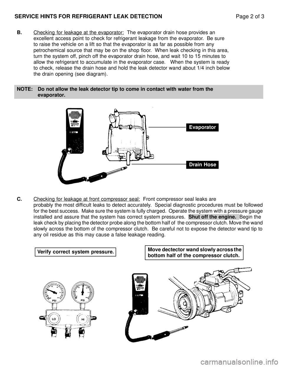
B.Checking for leakage at the evaporator: The evaporator drain hose provides an
excellent access point to check for refrigerant leakage from the evapora\
tor. Be sure
to raise the vehicle on a lift so that the evaporator is as far as possi\
ble from any
petrochemical source that may be on the shop floor. When leak checking in this area,
turn the system off, pinch off the evaporator drain hose, and wait 10 to 15 minutes to
allow the refrigerant to accumulate in the evaporator case. When the s\
ystem is ready
to check, release the drain hose and hold the leak detector wand about 1\
/4 inch below
the drain opening (see diagram).
NOTE: Do not allow the leak detector tip to come in contact with water from th\
e evaporator.
C. Checking for leakage at front compressor seal:
Front compressor seal leaks are
probably the most difficult leaks to detect accurately. Special diagnostic procedures must be followed
for the best success. Make sure the system is fully charged. Operate the \
system with a pressure gauge
installed and assure that the system has correct system pressures. Shut off the engine. Begin the
leak check by placing the detector probe along the bottom half of the compr\
essor clutch. Move the wand
slowly across the bottom of the compressor clutch. Be careful not to expose t\
he detector wand tip to
any oil residue as this may cause a false leakage reading.
Evaporator
Drain Hose
Verify correct system pressure. Move dectector wand slowly across the
bottom half of the compressor clutch.
WhereEverybodyKnowsYourName
Page 3845 of 4087

230
AUTOMATIC AIR CONDITIONER
MHOT COOL
I27 I27
I27
I27
E18
I28
EB1
7
IN1
4 II1 4
IQ1
5
II1
1
IR2
3 IR1
4IR1 10 IR1 9IR18IR1 13 IR112
2 1
2 1
2 1
B
8B 3B10 B 9B18 B 22 C 2C3B 20 B 25 C 9C8 BR
BR±W
BR
BR ±W BR
BR
BR±W
G±W
V
R±Y
BR
BR
BR
BR
BR
P± B
G±Y
P±B
P
L±Y
BR±W
G±W
V
R±Y
Y± R
Y±B
W BR±W
Y± R
BR BR±W
G± W
V
R±Y
Y±G Y±L
TAM LCKI TW TE S5 TP MH MC SG TPM MDEF MFACE 26 1 54
AIR MIX CONTROL
SERVO MOTOR
A/C CONTROL ASSEMBLY
A/C LOCK SENSOR A/C AMBIENT
TEMP. SEN SOR A/C SOLAR SENSOR
A1
A2
A20
A27
A12 , A 1 3 , A 1 4 CAB
BR± W
I27
I27
3 1
W4
WATER TEMP. SENSOR2 1 IR1
5
IR2
8IR1 7
I29IR1
11A/C EVAPORATOR
TEMP. SENSOR A16
BR±W
Y±GY±L W
BR
BR
Y±G
BR BR±W
BR BR BR
BR ±W
BR
BR BR
G± Y
LG±R G± Y
Y±R Y± B WW
BRBR
IQ1
6
BR BR
WhereEverybodyKnowsYourName
Page 3869 of 4087

27
Position of Parts in Engine Compartment
I 1 ISC Valve S 3Speed Sensor No. 1
I 2 Igniter S 4 Speed Sensor No. 2 (for ECT)
I 4 Ignition Coil S 6 Starter
I 6 Injector No. 1 S 7 Starter
I 7 Injector No. 2 S 8 Sub Throttle Actuator
I 8 Injector No. 3 S 9 Sub Throttle Position Sensor
I 9 Injector No. 4
I 10 Injector No. 5 T 1 Theft Deterrent Horn
I 11 Injector No. 6 T 2 Throttle Position Sensor T 3 Traction Brake Actuator
K 1 Knock Sensor No. 1 (on Front Side) T 4 Traction Brake Actuator
K 2 Knock Sensor No. 2 (on Rear Side) T 5 Traction pump and Motor
N 1 Neutral Start SW, Back±Up Light SW and A/T Indicator SW V 1 VSV (for EGR) (Exc. USA Spec) (for A/T) V 2 VSV (for EVAP)
N 2 Noise Filter (for Defogger System) V 4 VSV (for Water Valve)
N 3 Noise Filter (for Ignition System) V 7 VSV (for Intake Control Valve)
O 2 Oil Pressure SW W 1 Washer Level SW
O 3 Oxygen Sensor Main No. 1 (on Front Side) W 2 Washer Motor
O 4 Oxygen Sensor Main No. 2 (on Rear Side) W 3 Water Temp. Sender W 5 Wiper Motor
P 1 PPS Solenoid
P 20 Power Steering Pressure SW
WhereEverybodyKnowsYourName
Page 3870 of 4087

28
ELECTRICAL WIRING ROUTING
Position of Parts in Instrument Panel
A 12 A/C Control Assembly C 9 CD Player
A 13 A/C Control Assembly C 10 Center Airbag Sensor Assembly
A 14 A/C Control Assembly C 11 Cigarette Lighter
A 15 A/C Control SW and Radio SW C 12 Combination Meter
A 16 A/C Evaporator Temp. Sensor C 13 Combination Meter
A 17 A/C Power Transistor C 14Combination Meter
A 18 A/C Power Transistor C 15 Combination SW
A 19 A/C Room Temp. Sensor C 16 Combination SW
A 20 A/C Solar Sensor C 17 Combination SW
A 21 A/T Indicator Light (for Shift Lever) C 19 Cruise Control ECU
A 22 ABS ECU (for M/T, w/o Traction Control) C 23 Clutch Start SW
A 23 ABS ECU (for M/T, w/o Traction Control) C 24 Cruise Control Clutch SW
A 24 ABS and Traction ECU
A 25 ABS and Traction ECU D 1 Diode (for Brake Fluid Level)
A 26 ABS and Traction ECU D 2 Diode (for Parking Brake)
A 27 Air Mix Control Servo Motor D 3 Diode (for Tension Reduser)
A 28 Air Vent Mode Control Servo Motor
A 29 Airbag Squib E 8 ECT Pattern Select SW
A 33 Air Inlet Control Servo Motor E 9 Engine and ECT ECU (for A/T) E 10 Engine and ECT ECU (for A/T)
B 2 Blower Motor E 11 Engine ECU (for M/T)
B 3 Blower Resistor (for Low Speed) E 12 Engine ECU (for M/T)
F 10 Fuel Lid Opener SW
G 1 Glove Box Light
G 2 Glove Box Light SW
WhereEverybodyKnowsYourName