spark plugs LEXUS SC400 1991 Service User Guide
[x] Cancel search | Manufacturer: LEXUS, Model Year: 1991, Model line: SC400, Model: LEXUS SC400 1991Pages: 4087, PDF Size: 75.75 MB
Page 1658 of 4087

6. REMOVE THROTTLE BODY WITH INTAKE AIRCONNECTOR
(a) Disconnect the following hoses and connectors:(1) PCV hose
(2) Three vacuum hoses
(3) VSV (for EGR) connector
(4) Throttle position sensor connector
(5) IAC valve connector
(6) (w/ TRAC)
Sub±throttle position sensor connector
(7) (w/ TRAC) Sub±throttle actuator connector
(8) (USA spec. only)
EGR gas temperature sensor connector
(b) Remove the four bolts and two nuts holding the intake air connector to the intake chamber.
(c) Remove the VSV nut.
(d) Disc onnect the two water by±pass hoses from the
throttle body. Plug the hose ends.
(e) Remove the throttle body with the intake air connector and gasket.
7. REMOVE NO. 3 TIMING BELT COVER AND CYLINDER
HEAD REAR COVER
(a) Remove the oil filler cap.
(b) Using a 5 mm hexagon wrench, remove the ten bolts,No. 3 timing belt cover and cylinder head rear cover.
8. DISCONNECT HIGH±TENSION CORDS FROM SPARK PLUGS
(a) Remove the bolt holding the cord clamp from thecylinder head.
(b) Disconnect the two high±tension cord clamps from the No. 3 cylinder head cover.
(c) Disconnect the high±tension cords at the rubber boot. Do not pull on the cords.
NOTICE: Pulling on or bending the cords may damage
the conductor inside.
±
ENGINE MECHANICAL Engine Tune±UpEM±11
WhereEverybodyKnowsYourName
Page 1664 of 4087
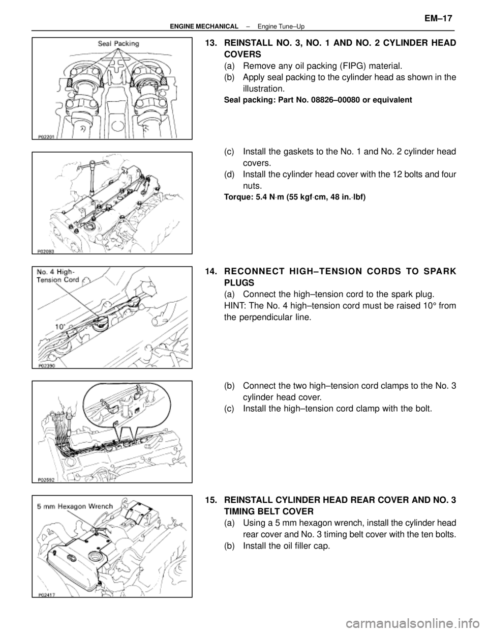
13. REINSTALL NO. 3, NO. 1 AND NO. 2 CYLINDER HEADCOVERS
(a) Remove any oil packing (FIPG) material.
(b) Apply seal packing to the cylinder head as shown in theillustration.
Seal packing: Part No. 08826±00080 or equivalent
(c) Install the gaskets to the No. 1 and No. 2 cylinder headcovers.
(d) Install the cylinder head cover with the 12 bolts and four
nuts.
Torque: 5.4 N Vm (55 kgf Vcm, 48 in. Vlbf)
14. R E C O N N E C T H I G H ± T E N S I O N C O R D S TO S PA R K
PLUGS
(a) Connect the high±tension cord to the spark plug.
HINT: The No. 4 high±tension cord must be raised 10 5 from
the perpendicular line.
(b) Connect the two high±tension cord clamps to the No. 3 cylinder head cover.
(c) Install the high±tension cord clamp with the bolt.
15. REINSTALL CYLINDER HEAD REAR COVER AND NO. 3 TIMING BELT COVER
(a) Using a 5 mm hexagon wrench, install the cylinder head
rear cover and No. 3 timing belt cover with the ten bolts.
(b) Install the oil filler cap.
±
ENGINE MECHANICAL Engine Tune±UpEM±17
WhereEverybodyKnowsYourName
Page 1673 of 4087
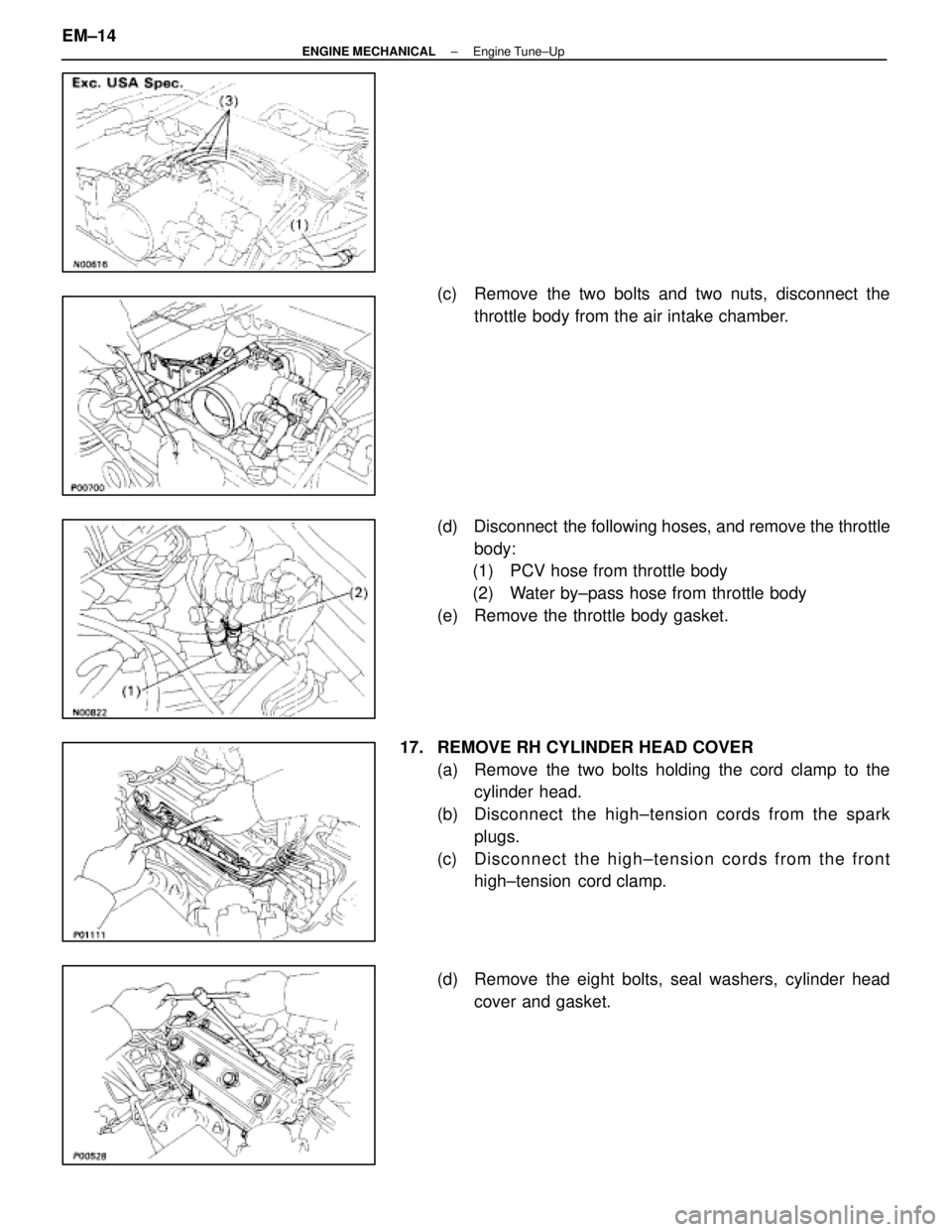
(c) Remove the two bolts and two nuts, disconnect thethrottle body from the air intake chamber.
(d) Disconnect the following hoses, and remove the throttle body:
(1) PCV hose from throttle body
(2) Water by±pass hose from throttle body
(e) Remove the throttle body gasket.
17. REMOVE RH CYLINDER HEAD COVER (a) Remove the two bolts holding the cord clamp to thecylinder head.
(b) Disc onnect the high±tension cords from the spark
plugs.
(c) Disconnect the high±tension cords from the front high±tension cord clamp.
(d) Remove the eight bolts, seal washers, cylinder head cover and gasket.
EM±14
±
ENGINE MECHANICAL Engine Tune±Up
WhereEverybodyKnowsYourName
Page 1674 of 4087
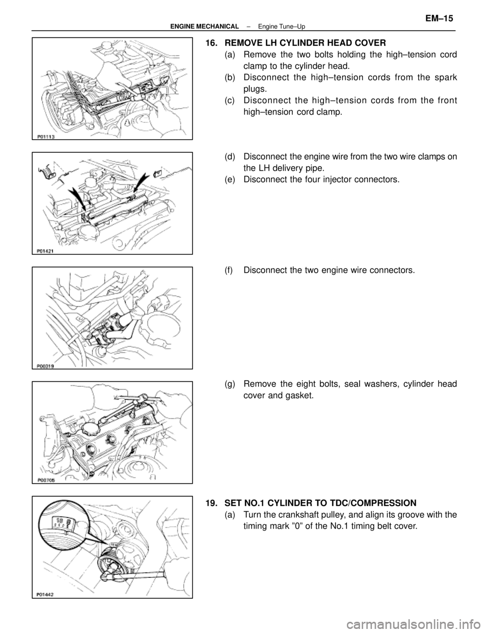
16. REMOVE LH CYLINDER HEAD COVER(a) Remove the two bolts holding the high±tension cordclamp to the cylinder head.
(b) Disc onnect the high±tension cords from the spark
plugs.
(c) Disconnect the high±tension cords from the front high±tension cord clamp.
(d) Disconnect the engine wire from the two wire clamps on
the LH delivery pipe.
(e) Disconnect the four injector connectors.
(f) Disconnect the two engine wire connectors.
(g) Remove the eight bolts, seal washers, cylinder head
cover and gasket.
19. SET NO.1 CYLINDER TO TDC/COMPRESSION (a) Turn the crankshaft pulley, and align its groove with thetiming mark º0º of the No.1 timing belt cover.
±
ENGINE MECHANICAL Engine Tune±UpEM±15
WhereEverybodyKnowsYourName
Page 1681 of 4087
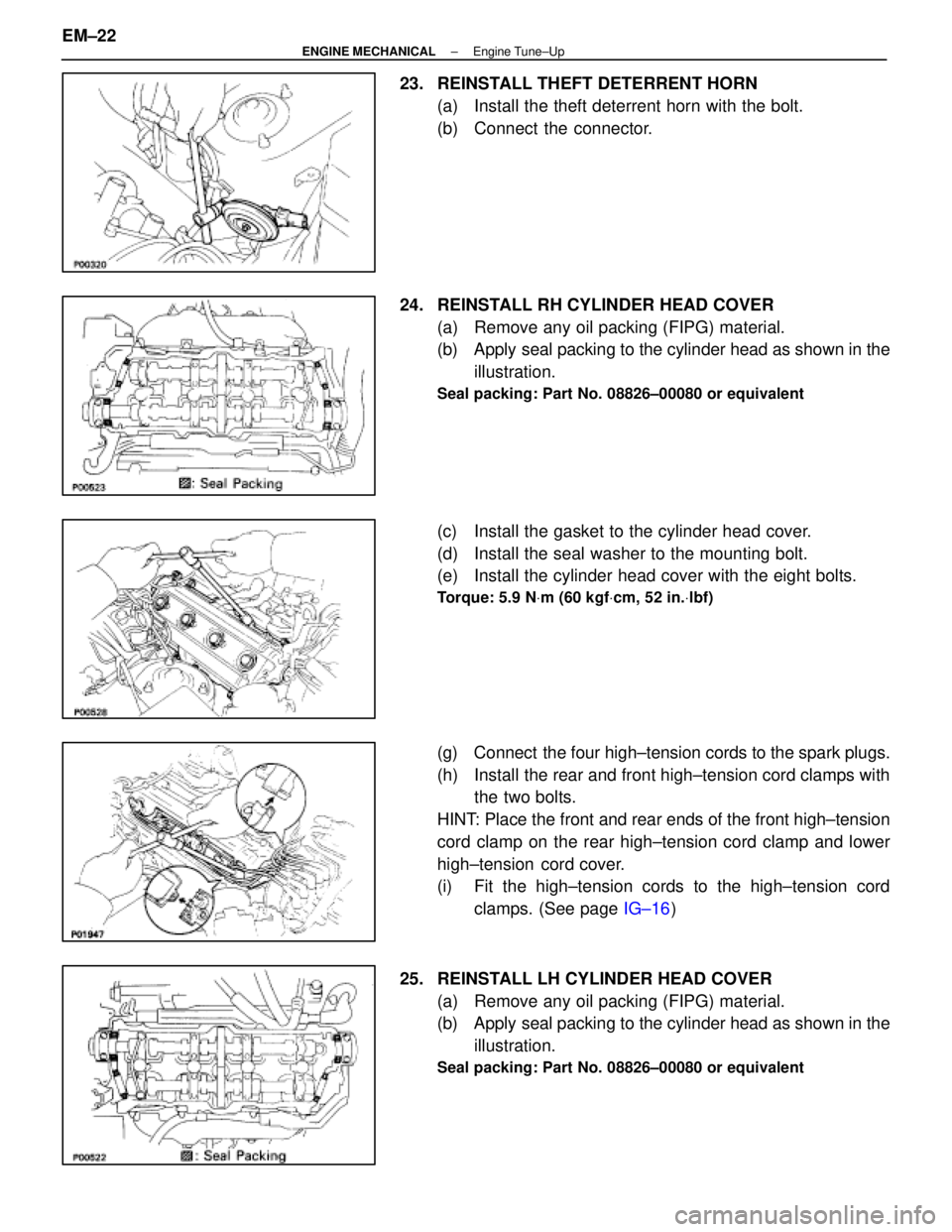
23. REINSTALL THEFT DETERRENT HORN(a) Install the theft deterrent horn with the bolt.
(b) Connect the connector.
24. REINSTALL RH CYLINDER HEAD COVER (a) Remove any oil packing (FIPG) material.
(b) Apply seal packing to the cylinder head as shown in theillustration.
Seal packing: Part No. 08826±00080 or equivalent
(c) Install the gasket to the cylinder head cover.
(d) Install the seal washer to the mounting bolt.
(e) Install the cylinder head cover with the eight bolts.
Torque: 5.9 N Vm (60 kgf Vcm, 52 in. Vlbf)
(g) Connect the four high±tension cords to the spark plugs.
(h) Install the rear and front high±tension cord clamps with
the two bolts.
HINT: Place the front and rear ends of the front high±tension
cord clamp on the rear high±tension cord clamp and lower
high±tension cord cover.
(i) Fit the high±tension cords to the high±tension cord clamps. (See page IG±16)
25. REINSTALL LH CYLINDER HEAD COVER (a) Remove any oil packing (FIPG) material.
(b) Apply seal packing to the cylinder head as shown in theillustration.
Seal packing: Part No. 08826±00080 or equivalent
EM±22±
ENGINE MECHANICAL Engine Tune±Up
WhereEverybodyKnowsYourName
Page 1682 of 4087
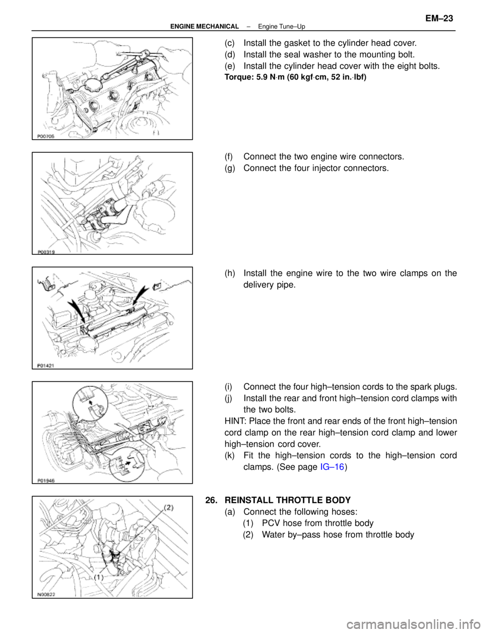
(c) Install the gasket to the cylinder head cover.
(d) Install the seal washer to the mounting bolt.
(e) Install the cylinder head cover with the eight bolts.
Torque: 5.9 NVm (60 kgf Vcm, 52 in. Vlbf)
(f) Connect the two engine wire connectors.
(g) Connect the four injector connectors.
(h) Install the engine wire to the two wire clamps on the
delivery pipe.
(i) Connect the four high±tension cords to the spark plugs.
(j) Install the rear and front high±tension cord clamps with the two bolts.
HINT: Place the front and rear ends of the front high±tension
cord clamp on the rear high±tension cord clamp and lower
high±tension cord cover.
(k) Fit the high±tension cords to the high±tension cord clamps. (See page IG±16)
26. REINSTALL THROTTLE BODY (a) Connect the following hoses:(1) PCV hose from throttle body
(2) Water by±pass hose from throttle body
±
ENGINE MECHANICAL Engine Tune±UpEM±23
WhereEverybodyKnowsYourName
Page 1689 of 4087
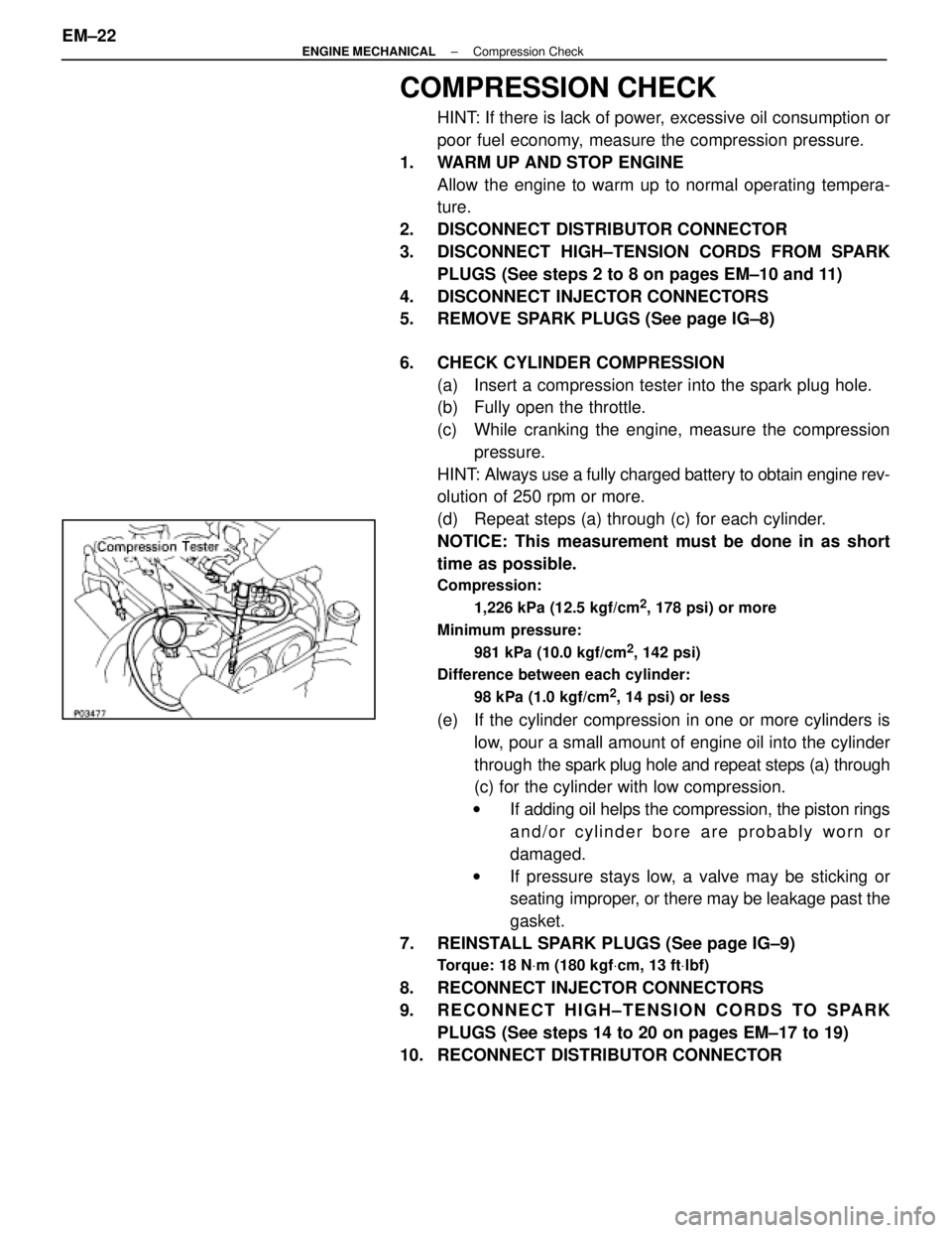
COMPRESSION CHECK
HINT: If there is lack of power, excessive oil consumption or
poor fuel economy, measure the compression pressure.
1. WARM UP AND STOP ENGINE Allow the engine to warm up to normal operating tempera-
ture.
2. DISCONNECT DISTRIBUTOR CONNECTOR
3. DISCONNECT HIGH±TENSION CORDS FROM SPARK PLUGS (See steps 2 to 8 on pages EM±10 and 11)
4. DISCONNECT INJECTOR CONNECTORS
5. REMOVE SPARK PLUGS (See page IG±8)
6. CHECK CYLINDER COMPRESSION (a) Insert a compression tester into the spark plug hole.
(b) Fully open the throttle.
(c) While cranking the engine, measure the compressionpressure.
HINT: Always use a fully charged battery to obtain engine rev-
olution of 250 rpm or more.
(d) Repeat steps (a) through (c) for each cylinder.
NOTICE: This measurement must be done in as short
time as possible.
Compression:
1,226 kPa (12.5 kgf/cm
2, 178 psi) or more
Minimum pressure: 981 kPa (10.0 kgf/cm
2, 142 psi)
Difference between each cylinder:
98 kPa (1.0 kgf/cm
2, 14 psi) or less
(e) If the cylinder compression in one or more cylinders islow, pour a small amount of engine oil into the cylinder
through the spark plug hole and repeat steps (a) through
(c) for the cylinder with low compression.
w If adding oil helps the compression, the piston rings
and/or cylinder bore are probably worn or
damaged.
w If pressure stays low, a valve may be sticking or
seating improper, or there may be leakage past the
gasket.
7. REINSTALL SPARK PLUGS (See page IG±9)
Torque: 18 N Vm (180 kgf Vcm, 13 ft Vlbf)
8. RECONNECT INJECTOR CONNECTORS
9. RECONNECT HIGH±TENSION CORDS TO SPARK
PLUGS (See steps 14 to 20 on pages EM±17 to 19)
10. RECONNECT DISTRIBUTOR CONNECTOR
EM±22
±
ENGINE MECHANICAL Compression Check
WhereEverybodyKnowsYourName
Page 1703 of 4087
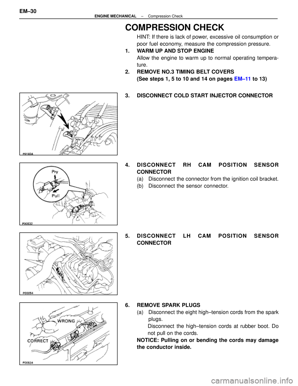
COMPRESSION CHECK
HINT: If there is lack of power, excessive oil consumption or
poor fuel economy, measure the compression pressure.
1. WARM UP AND STOP ENGINE Allow the engine to warm up to normal operating tempera-
ture.
2. REMOVE NO.3 TIMING BELT COVERS (See steps 1, 5 to 10 and 14 on pages EM±11 to 13)
3. DISCONNECT COLD START INJECTOR CONNECTOR
4. DISCONNECT RH CAM POSITION SENSOR CONNECTOR
(a) Disconnect the connector from the ignition coil bracket.
(b) Disconnect the sensor connector.
5. DISCONNECT LH CAM POSITION SENSOR CONNECTOR
6. REMOVE SPARK PLUGS (a) Disconnect the eight high±tension cords from the sparkplugs.
Disconnect the high±tension cords at rubber boot. Do
not pull on the cords.
NOTICE: Pulling on or bending the cords may damage
the conductor inside.
EM±30
±
ENGINE MECHANICAL Compression Check
WhereEverybodyKnowsYourName
Page 1704 of 4087
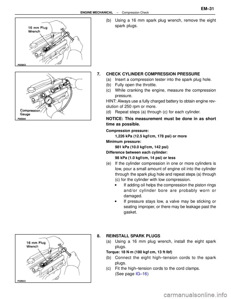
(b) Using a 16 mm spark plug wrench, remove the eightspark plugs.
7. CHECK CYLINDER COMPRESSION PRESSURE (a) Insert a compression tester into the spark plug hole.
(b) Fully open the throttle.
(c) While cranking the engine, measure the compressionpressure.
HINT: Always use a fully charged battery to obtain engine rev-
olution of 250 rpm or more.
(d) Repeat steps (a) through (c) for each cylinder.
NOTICE: This measurement must be done in as short
time as possible.
Compression pressure:
1,226 kPa (12.5 kgf/cm, 178 psi) or more
Minimum pressure: 981 kPa (10.0 kgf/cm, 142 psi)
Difference between each cylinder:
98 kPa (1.0 kgf/cm, 14 psi) or less
(e) If the cylinder compression in one or more cylinders islow, pour a small amount of engine oil into the cylinder
through the spark plug hole and repeat steps (a) through
(c) for the cylinder with low compression.
w If adding oil helps the compression the piston rings
and/or cylinder bore are probably worn or
damaged.
w If pressure stays low, a valve may be sticking or
seating improper, or there may be leakage past the
gasket.
8. REINSTALL SPARK PLUGS (a) Using a 16 mm plug wrench, install the eight sparkplugs.
Torque: 18 N Vm (180 kgf Vcm, 13 ft Vlbf)
(b) C onnect the eight high±tension cords to the spark
plugs.
(c) Fit the high±tension cords to the cord clamps.
(See page IG±16)
±
ENGINE MECHANICAL Compression CheckEM±31
WhereEverybodyKnowsYourName
Page 1711 of 4087
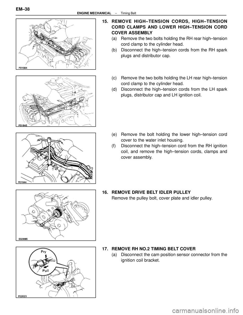
15. REMOVE HIGH±TENSION CORDS, HIGH±TENSIONCORD CLAMPS AND LOWER HIGH±TENSION CORD
COVER ASSEMBLY
(a) Remove the two bolts holding the RH rear high±tensioncord clamp to the cylinder head.
(b) Disconnect the high±tension cords from the RH spark plugs and distributor cap.
(c) Remove the two bolts holding the LH rear high±tension cord clamp to the cylinder head.
(d) Disconnect the high±tension cords from the LH spark
plugs, distributor cap and LH ignition coil.
(e) Remove the bolt holding the lower high±tension cord cover to the water inlet housing.
(f) Disconnect the high±tension cord from the RH ignition
coil, and remove the high±tension cords, clamps and
cover assembly.
16. REMOVE DRIVE BELT IDLER PULLEY Remove the pulley bolt, cover plate and idler pulley.
17. REMOVE RH NO.2 TIMING BELT COVER (a) Disconnect the cam position sensor connector from theignition coil bracket.
EM±38
±
ENGINE MECHANICAL Timing Belt
WhereEverybodyKnowsYourName