LEXUS SC400 1991 Service Repair Manual
Manufacturer: LEXUS, Model Year: 1991, Model line: SC400, Model: LEXUS SC400 1991Pages: 4087, PDF Size: 75.75 MB
Page 2571 of 4087
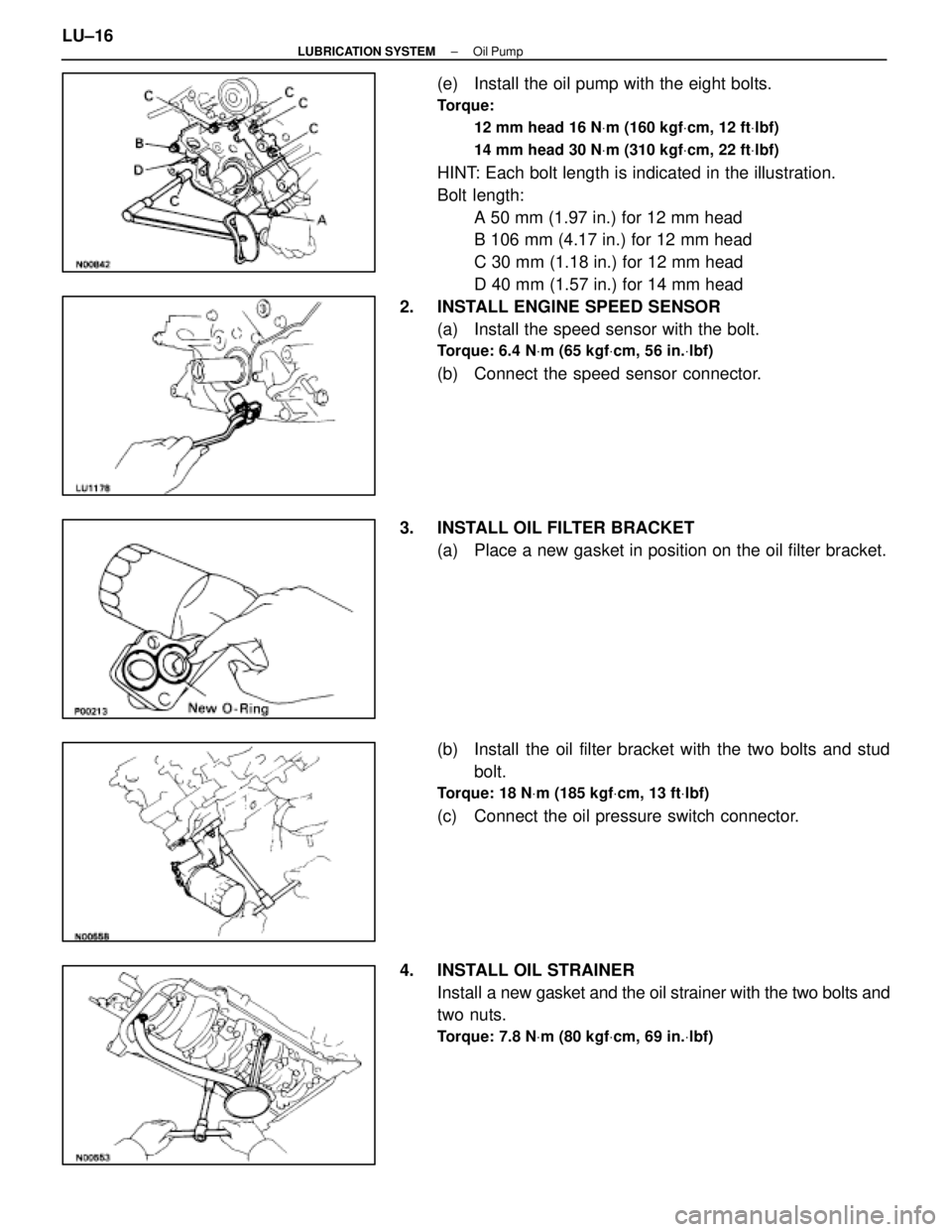
(e) Install the oil pump with the eight bolts.
Torque:12 mm head 16 N Vm (160 kgf Vcm, 12 ft Vlbf)
14 mm head 30 N Vm (310 kgf Vcm, 22 ft Vlbf)
HINT: Each bolt length is indicated in the illustration.
Bolt length:
A 50 mm (1.97 in.) for 12 mm head
B 106 mm (4.17 in.) for 12 mm head
C 30 mm (1.18 in.) for 12 mm head
D 40 mm (1.57 in.) for 14 mm head
2. INSTALL ENGINE SPEED SENSOR (a) Install the speed sensor with the bolt.
Torque: 6.4 N Vm (65 kgf Vcm, 56 in. Vlbf)
(b) Connect the speed sensor connector.
3. INSTALL OIL FILTER BRACKET (a) Place a new gasket in position on the oil filter bracket.
(b) Install the oil filter bracket with the two bolts and studbolt.
Torque: 18 N Vm (185 kgf Vcm, 13 ft Vlbf)
(c) Connect the oil pressure switch connector.
4. INSTALL OIL STRAINER Install a new gasket and the oil strainer with the two bolts and
two nuts.
Torque: 7.8 N Vm (80 kgf Vcm, 69 in. Vlbf)
LU±16±
LUBRICATION SYSTEM Oil Pump
WhereEverybodyKnowsYourName
Page 2572 of 4087
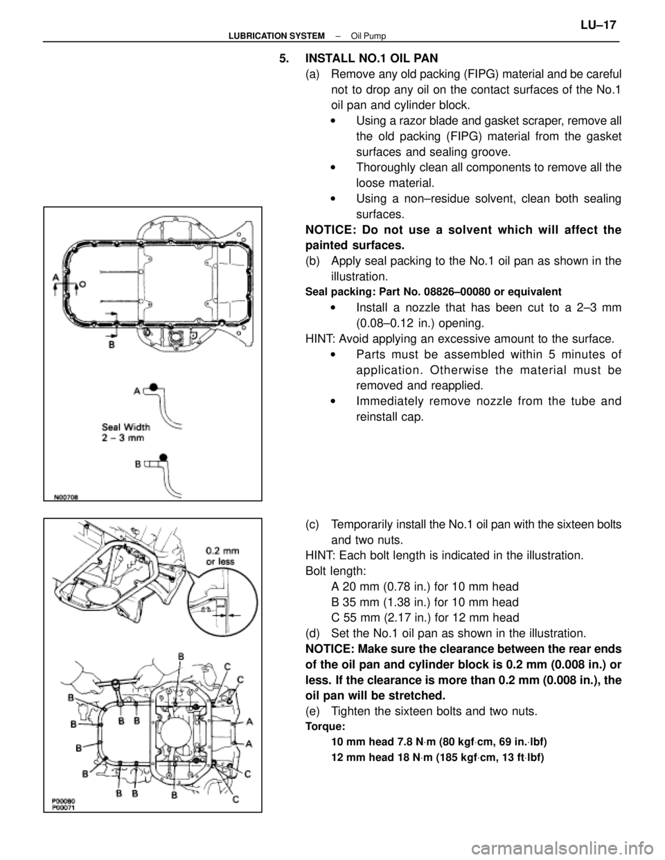
5. INSTALL NO.1 OIL PAN(a) Remove any old packing (FIPG) material and be carefulnot to drop any oil on the contact surfaces of the No.1
oil pan and cylinder block.
w Using a razor blade and gasket scraper, remove all
the old packing (FIPG) material from the gasket
surfaces and sealing groove.
w Thoroughly clean all components to remove all the
loose material.
w Using a non±residue solvent, clean both sealing
surfaces.
NOTICE: Do not use a solvent which will affect the
painted surfaces.
(b) Apply seal packing to the No.1 oil pan as shown in the illustration.
Seal packing: Part No. 08826±00080 or equivalent
w Install a nozzle that has been cut to a 2±3 mm
(0.08±0.12 in.) opening.
HINT: Avoid applying an excessive amount to the surface. w Parts must be assembled within 5 minutes of
application. Otherwise the material must be
removed and reapplied.
w Immediately remove nozzle from the tube and
reinstall cap.
(c) Temporarily install the No.1 oil pan with the sixteen bolts
and two nuts.
HINT: Each bolt length is indicated in the illustration.
Bolt length:
A 20 mm (0.78 in.) for 10 mm head
B 35 mm (1.38 in.) for 10 mm head
C 55 mm (2.17 in.) for 12 mm head
(d) Set the No.1 oil pan as shown in the illustration.
NOTICE: Make sure the clearance between the rear ends
of the oil pan and cylinder block is 0.2 mm (0.008 in.) or
less. If the clearance is more than 0.2 mm (0.008 in.), the
oil pan will be stretched.
(e) Tighten the sixteen bolts and two nuts.
Torque:
10 mm head 7.8 N Vm (80 kgf Vcm, 69 in. Vlbf)
12 mm head 18 N Vm (185 kgf Vcm, 13 ft Vlbf)
±
LUBRICATION SYSTEM Oil PumpLU±17
WhereEverybodyKnowsYourName
Page 2573 of 4087
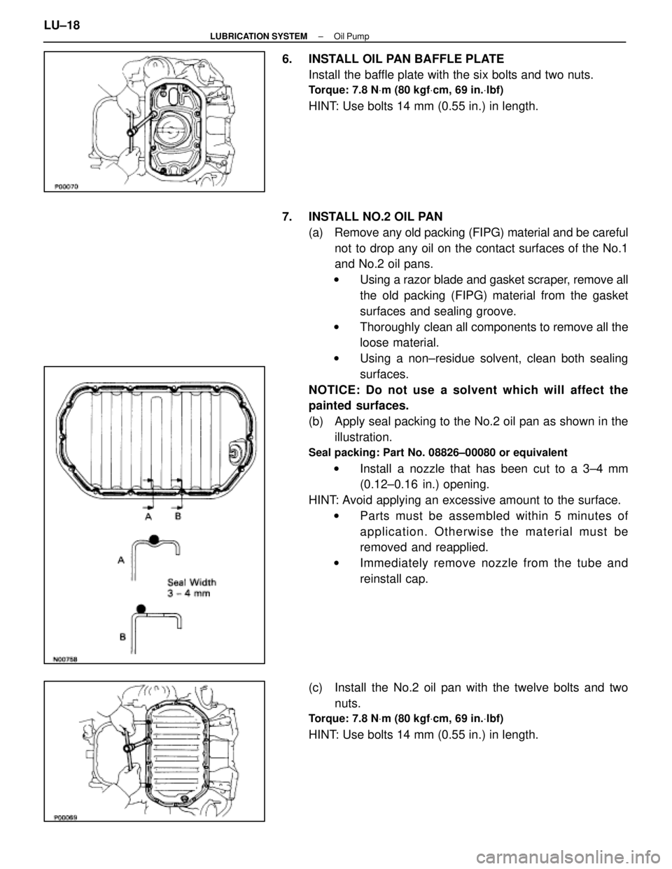
6. INSTALL OIL PAN BAFFLE PLATEInstall the baffle plate with the six bolts and two nuts.
Torque: 7.8 N Vm (80 kgf Vcm, 69 in. Vlbf)
HINT: Use bolts 14 mm (0.55 in.) in length.
7. INSTALL NO.2 OIL PAN (a) Remove any old packing (FIPG) material and be carefulnot to drop any oil on the contact surfaces of the No.1
and No.2 oil pans.
w Using a razor blade and gasket scraper, remove all
the old packing (FIPG) material from the gasket
surfaces and sealing groove.
w Thoroughly clean all components to remove all the
loose material.
w Using a non±residue solvent, clean both sealing
surfaces.
NOTICE: Do not use a solvent which will affect the
painted surfaces.
(b) Apply seal packing to the No.2 oil pan as shown in the illustration.
Seal packing: Part No. 08826±00080 or equivalent
w Install a nozzle that has been cut to a 3±4 mm
(0.12±0.16 in.) opening.
HINT: Avoid applying an excessive amount to the surface. w Parts must be assembled within 5 minutes of
application. Otherwise the material must be
removed and reapplied.
w Immediately remove nozzle from the tube and
reinstall cap.
(c) Install the No.2 oil pan with the twelve bolts and two nuts.
Torque: 7.8 N Vm (80 kgf Vcm, 69 in. Vlbf)
HINT: Use bolts 14 mm (0.55 in.) in length.
LU±18
±
LUBRICATION SYSTEM Oil Pump
WhereEverybodyKnowsYourName
Page 2574 of 4087
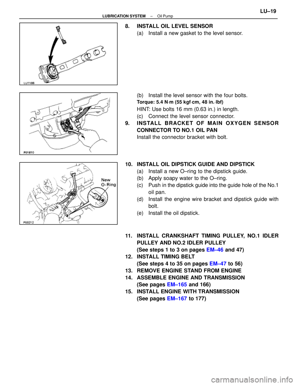
8. INSTALL OIL LEVEL SENSOR(a) Install a new gasket to the level sensor.
(b) Install the level sensor with the four bolts.
Torque: 5.4 N Vm (55 kgf Vcm, 48 in. Vlbf)
HINT: Use bolts 16 mm (0.63 in.) in length.
(c) Connect the level sensor connector.
9. INSTALL BRACKET OF MAIN OXYGEN SENSOR CONNECTOR TO NO.1 OIL PAN
Install the connector bracket with bolt.
10. INSTALL OIL DIPSTICK GUIDE AND DIPSTICK (a) Install a new O±ring to the dipstick guide.
(b) Apply soapy water to the O±ring.
(c) Push in the dipstick guide into the guide hole of the No.1
oil pan.
(d) Install the engine wire bracket and dipstick guide with bolt.
(e) Install the oil dipstick.
11. INSTALL CRANKSHAFT TIMING PULLEY, NO.1 IDLER PULLEY AND NO.2 IDLER PULLEY
(See steps 1 to 3 on pages EM±46 and 47)
12. INSTALL TIMING BELT
(See steps 4 to 35 on pages EM±47 to 56)
13. REMOVE ENGINE STAND FROM ENGINE
14. ASSEMBLE ENGINE AND TRANSMISSION (See pages EM±165 and 166)
15. INSTALL ENGINE WITH TRANSMISSION (See pages EM±167 to 177)
±
LUBRICATION SYSTEM Oil PumpLU±19
WhereEverybodyKnowsYourName
Page 2575 of 4087

SERVICE SPECIFICATIONS
SERVICE DATA
Oil pressureat idling29 kPa (0.3 kgf/cm2, 4.3 psi) or more
at 3,000 rpm 294±588 kPa
(3.0±6.0 kgf/cm2, 43±85 psi)
Oil pumpTip clearanceSTD0.110±0.240 mm0.0043±0.0094 in.
Limit 0.35 mm0.0138 in.
Side clearanceSTD 0.030±0.090 mm0.0012±0.0035 in.
Limit 0.15 mm0.0059 in.
Body clearanceSTD 0.100±0.175 mm0.0039±0.0069 in.
Limit0.30 mm0.0118 in.
TORQUE SPECIFICATIONS
Part tightenedNVmkgf Vcmft Vlbf
Oil oumo body cover X Oil pump body101058
Oil pump X Cylinder block12 mm head 16160 12
14 mm head 30310 22
Engine speed sensor X Oil pump6.465 56 in. Vlbf
Oil filter bracket X Oil pump18185 13
Oil strainer X Oil pump7.880 69 in. Vlbf
Oil strainer X Cylinder block7.880 69 in. Vlbf
No.2 oil pan X Cylinder block10 mm head 7.880 69 in. Vlbf
12 mm head 18185 13
Oil pan baffle plate X No.1 oil pan7.880 69 in. Vlbf
No.2 oil pan X No.1 oil pan7.880 69 in. Vlbf
No.2 oil pan X Cylinder block7.880 69 in. Vlbf
Oil level sensor X No.1 oil pan5.45548 in. Vlbf
LU±20±
LUBRICATION SYSTEM Service Specifications
WhereEverybodyKnowsYourName
Page 2576 of 4087

STARTING SYSTEM
STARTING SYSTEM
NOTE: The specification descriptions ºUSA Spec.º and
º Exc. USA Spec. º used in this section indicate the following
specifications.
USA Spec .: USA (50 States) Specifications
Exc. USA Spec .: USA (except California) and Canadian
Specifications.
ST±1
WhereEverybodyKnowsYourName
Page 2577 of 4087
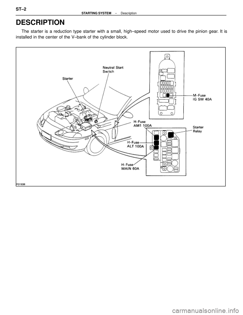
DESCRIPTION
The starter is a reduction type starter with a small, high±speed motor u\
sed to drive the pinion gear. It is
installed in the center of the V±bank of the cylinder block. ST±2
±
STARTING SYSTEM Description
WhereEverybodyKnowsYourName
Page 2578 of 4087
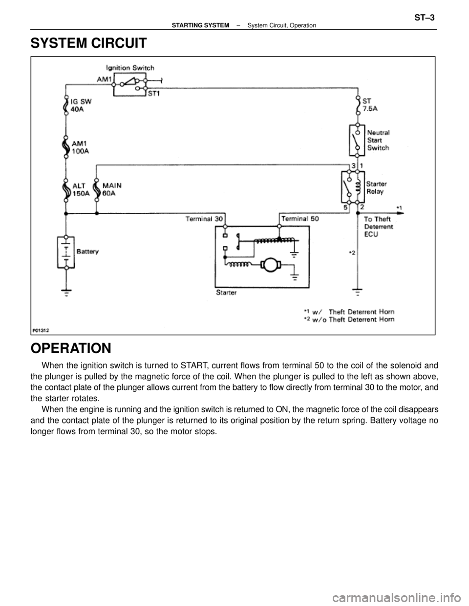
SYSTEM CIRCUIT
OPERATION
When the ignition switch is turned to START, current flows from terminal 50 to the coil of the solenoid and
the plunger is pulled by the magnetic force of the coil. When the plunger is pulled \
to the left as shown above,
the contact plate of the plunger allows current from the battery to flow di\
rectly from terminal 30 to the motor, and
the starter rotates. When the engine is running and the ignition switch is returned to ON, the ma\
gnetic force of the coil disappears
and the contact plate of the plunger is returned to its original position by the return spring. Battery voltage no
longer flows from terminal 30, so the motor stops.
±
STARTING SYSTEM System Circuit, OperationST±3
WhereEverybodyKnowsYourName
Page 2579 of 4087
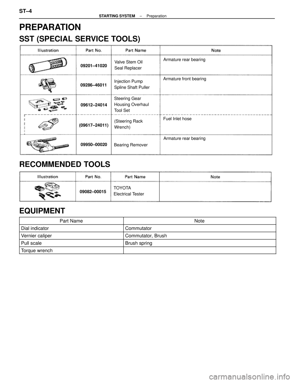
PREPARATION
SST (SPECIAL SERVICE TOOLS)
09201±41020Valve Stem Oil
Seal ReplacerArmature rear bearing
09286±46011Injection Pump
Spline Shaft PullerArmature front bearing
09612±24014
Steering Gear
Housing Overhaul
Tool Set
(09617±24011)(Steering Rack
Wrench)Fuel Inlet hose
09950±00020Bearing Remover
Armature rear bearing
RECOMMENDED TOOLS
09082±00015TOYOTA
Electrical Tester
EQUIPMENT
Part NameNote
Dial indicatorCommutator
Vernier caliperCommutator, Brush
Pull scaleBrush spring
Torque wrench
ST±4±
STARTING SYSTEM Preparation
WhereEverybodyKnowsYourName
Page 2580 of 4087
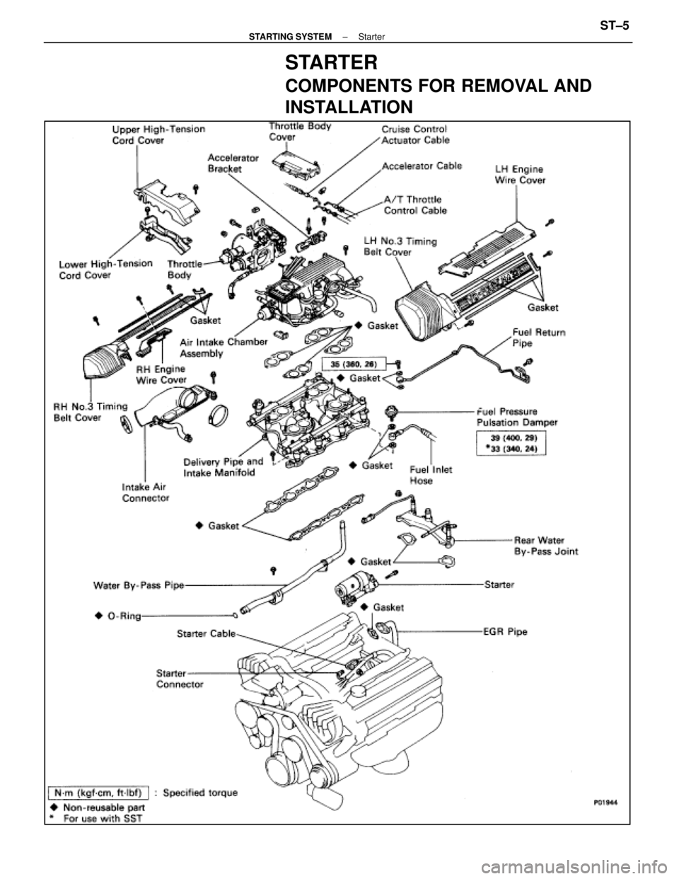
STARTER
COMPONENTS FOR REMOVAL AND
INSTALLATION
±
STARTING SYSTEM StarterST±5
WhereEverybodyKnowsYourName