oxygen sensor LEXUS SC400 1991 Service Owner's Manual
[x] Cancel search | Manufacturer: LEXUS, Model Year: 1991, Model line: SC400, Model: LEXUS SC400 1991Pages: 4087, PDF Size: 75.75 MB
Page 1775 of 4087
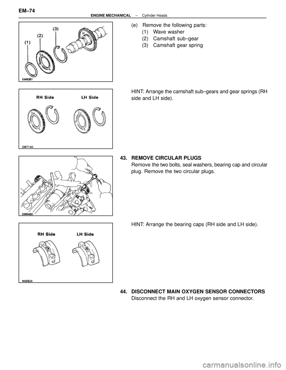
(e) Remove the following parts:(1) Wave washer
(2) Camshaft sub±gear
(3) Camshaft gear spring
HINT: Arrange the camshaft sub±gears and gear springs (RH
side and LH side).
43. REMOVE CIRCULAR PLUGS Remove the two bolts, seal washers, bearing cap and circular
plug. Remove the two circular plugs.
HINT: Arrange the bearing caps (RH side and LH side).
44. DISCONNECT MAIN OXYGEN SENSOR CONNECTORS Disconnect the RH and LH oxygen sensor connector.
EM±74
±
ENGINE MECHANICAL Cylinder Heads
WhereEverybodyKnowsYourName
Page 1776 of 4087
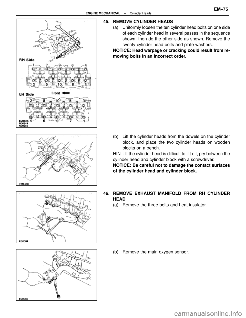
45. REMOVE CYLINDER HEADS(a) Uniformly loosen the ten cylinder head bolts on one side
of each cylinder head in several passes in the sequence
shown, then do the other side as shown. Remove the
twenty cylinder head bolts and plate washers.
NOTICE: Head warpage or cracking could result from re-
moving bolts in an incorrect order.
(b) Lift the cylinder heads from the dowels on the cylinder block, and place the two cylinder heads on wooden
blocks on a bench.
HINT: If the cylinder head is difficult to lift off, pry between the
cylinder head and cylinder block with a screwdriver.
NOTICE: Be careful not to damage the contact surfaces
of the cylinder head and cylinder block.
46. REMOVE EXHAUST MANIFOLD FROM RH CYLINDER HEAD
(a) Remove the three bolts and heat insulator.
(b) Remove the main oxygen sensor.
±
ENGINE MECHANICAL Cylinder HeadsEM±75
WhereEverybodyKnowsYourName
Page 1777 of 4087
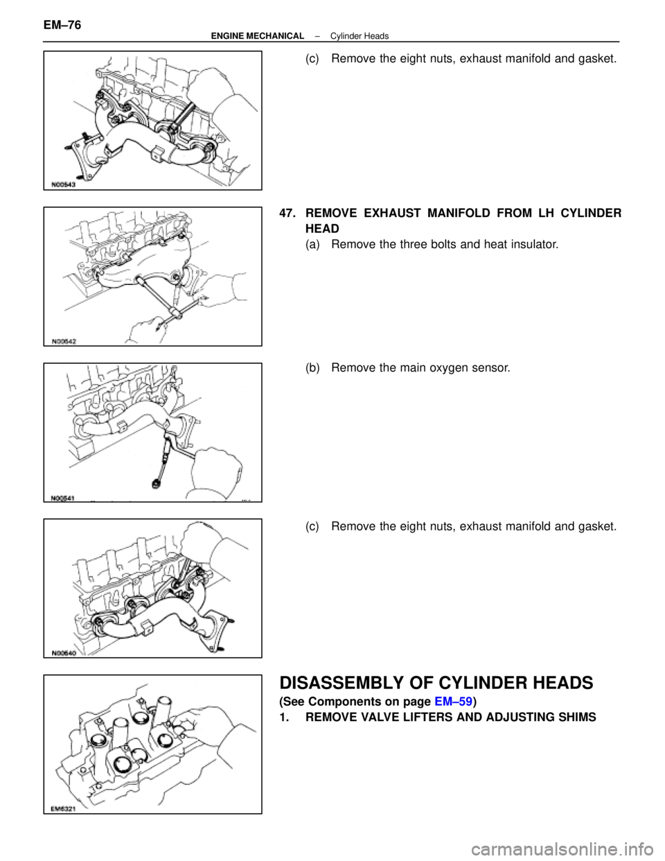
(c) Remove the eight nuts, exhaust manifold and gasket.
47. REMOVE EXHAUST MANIFOLD FROM LH CYLINDER HEAD
(a) Remove the three bolts and heat insulator.
(b) Remove the main oxygen sensor.
(c) Remove the eight nuts, exhaust manifold and gasket.
DISASSEMBLY OF CYLINDER HEADS
(See Components on page EM±59)
1. REMOVE VALVE LIFTERS AND ADJUSTING SHIMS
EM±76
±
ENGINE MECHANICAL Cylinder Heads
WhereEverybodyKnowsYourName
Page 1792 of 4087
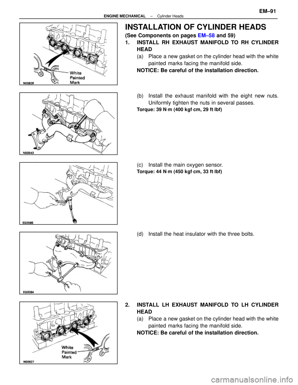
INSTALLATION OF CYLINDER HEADS
(See Components on pages EM±58 and 59)
1. INSTALL RH EXHAUST MANIFOLD TO RH CYLINDER HEAD
(a) Place a new gasket on the cylinder head with the white
painted marks facing the manifold side.
NOTICE: Be careful of the installation direction.
(b) Install the exhaust manifold with the eight new nuts. Uniformly tighten the nuts in several passes.
Torque: 39 N Vm (400 kgf Vcm, 29 ft Vlbf)
(c) Install the main oxygen sensor.
Torque: 44 N Vm (450 kgf Vcm, 33 ft Vlbf)
(d) Install the heat insulator with the three bolts.
2. INSTALL LH EXHAUST MANIFOLD TO LH CYLINDER HEAD
(a) Place a new gasket on the cylinder head with the whitepainted marks facing the manifold side.
NOTICE: Be careful of the installation direction.
±
ENGINE MECHANICAL Cylinder HeadsEM±91
WhereEverybodyKnowsYourName
Page 1793 of 4087
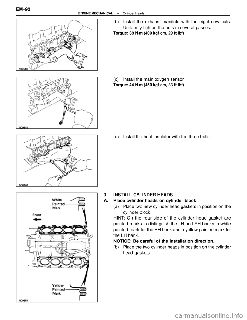
(b) Install the exhaust manifold with the eight new nuts.Uniformly tighten the nuts in several passes.
Torque: 39 N Vm (400 kgf Vcm, 29 ft Vlbf)
(c) Install the main oxygen sensor.
Torque: 44 N Vm (450 kgf Vcm, 33 ft Vlbf)
(d) Install the heat insulator with the three bolts.
3. INSTALL CYLINDER HEADS
A. Place cylinder heads on cylinder block (a) Place two new cylinder head gaskets in position on thecylinder block.
HINT: On the rear side of the cylinder head gasket are
painted marks to distinguish the LH and RH banks, a white
painted mark for the RH bank and a yellow painted mark for
the LH bank.
NOTICE: Be careful of the installation direction.
(b) Place the two cylinder heads in position on the cylinder
head gaskets.
EM±92
±
ENGINE MECHANICAL Cylinder Heads
WhereEverybodyKnowsYourName
Page 1794 of 4087
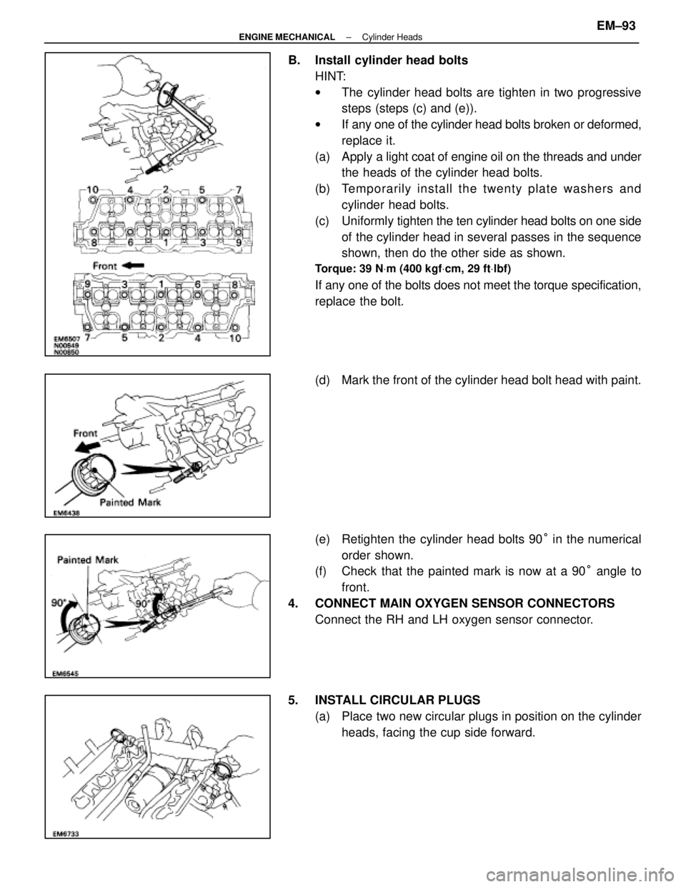
B. Install cylinder head boltsHINT:
wThe cylinder head bolts are tighten in two progressive
steps (steps (c) and (e)).
w If any one of the cylinder head bolts broken or deformed,
replace it.
(a) Apply a light coat of engine oil on the threads and under
the heads of the cylinder head bolts.
(b) Te mp o ra rily in sta ll th e twe n ty pla te wa sh e rs an d cylinder head bolts.
(c) Uniformly tighten the ten cylinder head bolts on one side
of the cylinder head in several passes in the sequence
shown, then do the other side as shown.
Torque: 39 N Vm (400 kgf Vcm, 29 ft Vlbf)
If any one of the bolts does not meet the torque specification,
replace the bolt.
(d) Mark the front of the cylinder head bolt head with paint.
(e) Retighten the cylinder head bolts 90 ° in the numerical
order shown.
(f) Check that the painted mark is now at a 90 ° angle to
front.
4. CONNECT MAIN OXYGEN SENSOR CONNECTORS Connect the RH and LH oxygen sensor connector.
5. INSTALL CIRCULAR PLUGS (a) Place two new circular plugs in position on the cylinderheads, facing the cup side forward.
±
ENGINE MECHANICAL Cylinder HeadsEM±93
WhereEverybodyKnowsYourName
Page 1923 of 4087
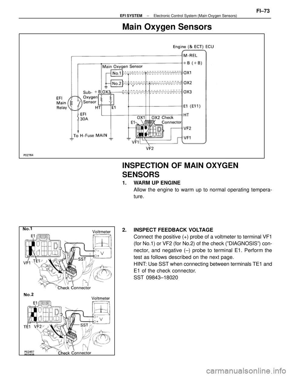
Main Oxygen Sensors
INSPECTION OF MAIN OXYGEN
SENSORS
1. WARM UP ENGINEAllow the engine to warm up to normal operating tempera-
ture.
2. INSPECT FEEDBACK VOLTAGE Connect the positive (+) probe of a voltmeter to terminal VF1
(for No.1) or VF2 (for No.2) of the check (ºDIAGNOSISº) con-\
nector, and negative (±) probe to terminal E1. Perform the
test as follows described on the next page.
HINT: Use SST when connecting between terminals TE1 and
E1 of the check connector.
SST 09843±18020
±
EFI SYSTEM Electronic Control System (Main Oxygen Sensors)FI±73
WhereEverybodyKnowsYourName
Page 1924 of 4087
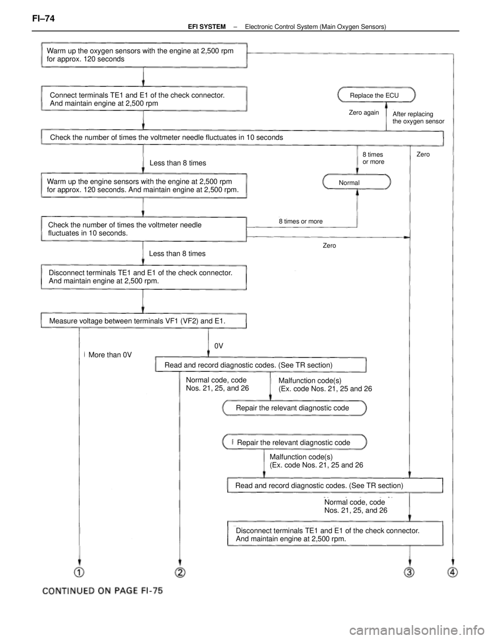
Replace the ECU
Zero againAfter replacing
the oxygen sensor
Normal
8 times
or moreZero
Check the number of times the voltmeter needle fluctuates in 10 seconds
Zero
8 times or more
Warm up the oxygen sensors with the engine at 2,500 rpm
for approx. 120 seconds
Connect terminals TE1 and E1 of the check connector.
And maintain engine at 2,500 rpm
Warm up the engine sensors with the engine at 2,500 rpm
for approx. 120 seconds. And maintain engine at 2,500 rpm.
Check the number of times the voltmeter needle
fluctuates in 10 seconds.
Less than 8 times
Disconnect terminals TE1 and E1 of the check connector.
And maintain engine at 2,500 rpm.
Measure voltage between terminals VF1 (VF2) and E1.
Less than 8 times
More than 0V
0V
Normal code, code
Nos. 21, 25, and 26Malfunction code(s)
(Ex. code Nos. 21, 25 and 26
Read and record diagnostic codes. (See TR section)
Repair the relevant diagnostic code
Disconnect terminals TE1 and E1 of the check connector.
And maintain engine at 2,500 rpm.
Read and record diagnostic codes. (See TR section)
Malfunction code(s)
(Ex. code Nos. 21, 25 and 26
Normal code, code
Nos. 21, 25, and 26
Repair the relevant diagnostic code
FI±74±
EFI SYSTEM Electronic Control System (Main Oxygen Sensors)
WhereEverybodyKnowsYourName
Page 1925 of 4087
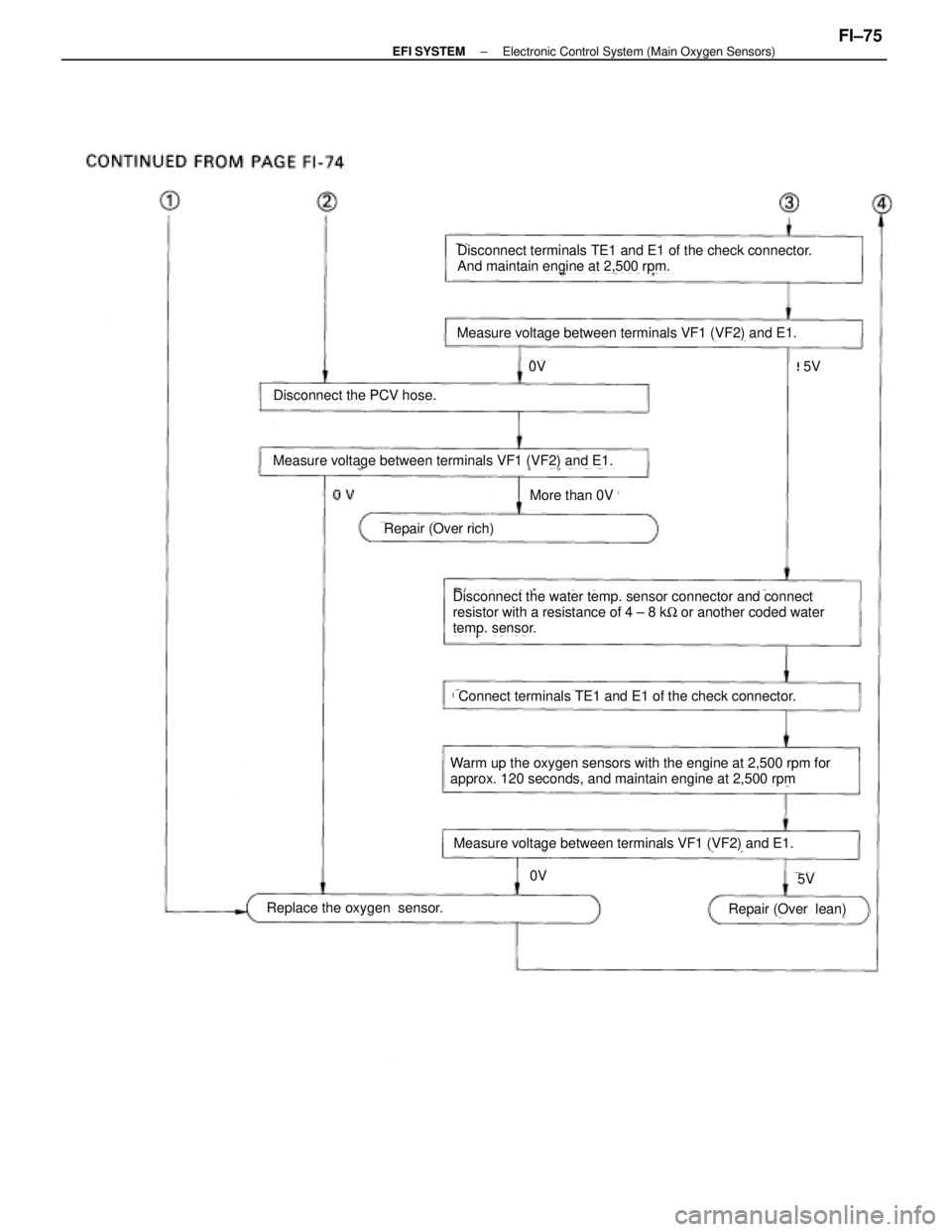
Measure voltage between terminals VF1 (VF2) and E1.
Disconnect terminals TE1 and E1 of the check connector.
And maintain engine at 2,500 rpm.
Measure voltage between terminals VF1 (VF2) and E1.
Disconnect the PCV hose.
0V
5V
More than 0V
Repair (Over rich)
Disconnect the water temp. sensor connector and connect
resistor with a resistance of 4 ± 8 kW or another coded water
temp. sensor.
Connect terminals TE1 and E1 of the check connector.
Warm up the oxygen sensors with the engine at 2,500 rpm for
approx. 120 seconds, and maintain engine at 2,500 rpm
Measure voltage between terminals VF1 (VF2) and E1.
Replace the oxygen sensor.Repair (Over lean)
5V
0V
±
EFI SYSTEM Electronic Control System (Main Oxygen Sensors)FI±75
WhereEverybodyKnowsYourName
Page 1926 of 4087
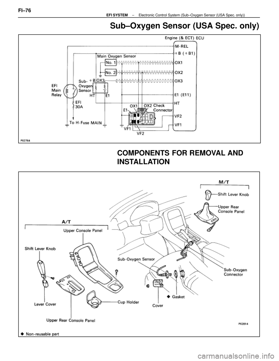
Sub±Oxygen Sensor (USA Spec. only)
COMPONENTS FOR REMOVAL AND
INSTALLATION
FI±76±
EFI SYSTEM Electronic Control System (Sub±Oxygen Sensor (USA Spec. only))
WhereEverybodyKnowsYourName