LEXUS SC400 1991 Service Repair Manual
Manufacturer: LEXUS, Model Year: 1991, Model line: SC400, Model: LEXUS SC400 1991Pages: 4087, PDF Size: 75.75 MB
Page 3921 of 4087
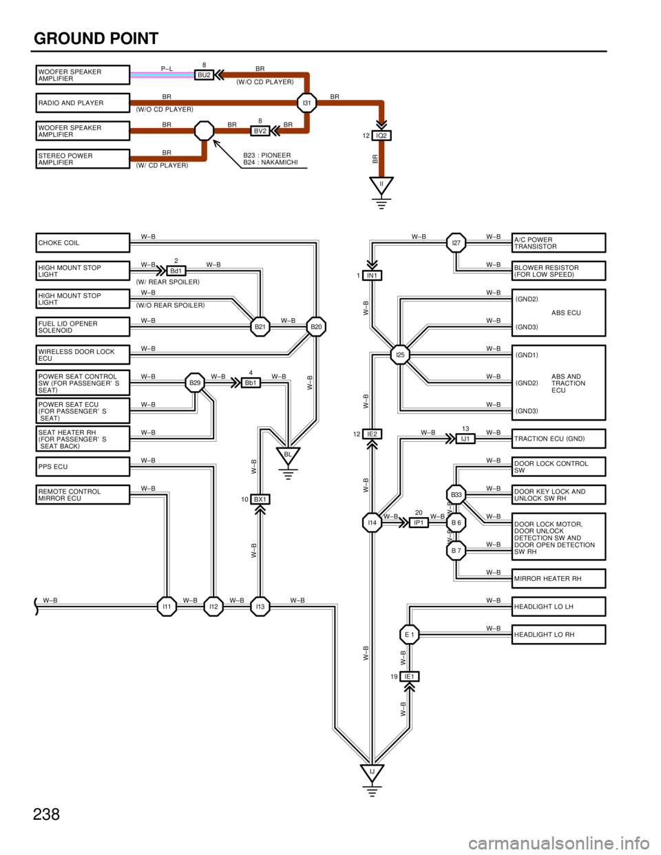
238
GROUND POINT
RADIO AND PLAYER
WOOFER SPEAKER
AMP LIFIER
STEREO POWER
AMP LIFIER
CHOKE COIL
HIGH MOUNT STOP
LIGHT
HIGH MOUNT STOP
LIGHT
FUEL LID OPENER
SOLENOID
WIRELESS DOOR LOCK
ECU
POWER SEAT CONTROL
SW(
FOR PASSENGER' S
SEAT )
POWER SEAT ECU
( FOR PASSENGER' S
SEAT )
SEAT HEATER RH
( FOR PASSENGER' S
SEAT BACK )
PPS ECU
REMOTE CONTROL
MIRROR ECU I31
II
BV2
8
IQ2
12
B23 : PIONEER
B24 : NAKAMICHI
BR
BR
BR BR
(
W/O CD PLAYER )
( W/ CD PLAYER ) BR
BR
A/C POWER
TRANSISTOR
BLOWER RESISTOR
(
FOR LOW SPEED )
ABS ECU
ABS AND
TRACTION
ECU
TRACTION ECU (
GND )
DOOR LOCK CONTROL
SW
MIRROR HEATER RH DOOR LOCK MOTOR,
D OOR UNL OC K
DETECTION SW AND
DOOR OPEN DETECTION
SW RH DOOR KEY LOCK AND
UNLOCK SW RH
HEADLIGHT LO LH
I25
I14 B33
B6
B7
HEADLIGHT LO RH
B20
B21
B29
E1
I11 I12 I13
IJ
BL
Bd1
2
Bb14
IJ113
IP1 20
IN1
1
IE2
12
IE1
19
BX1
10
W±B
W±B
W±B
W±B
W±B
W±B
W±B
W±B
W±B
W±B
W±B W±B W±B W±B W±B W±B
W±B
W±B W±B W±B
W±B
W±B
W±B
W±B
W±B
W±B
W±B
W±B
W±B
W±B
W±B
W±B
W±B
W±B W±B
W±B
W±B
W±B W±B
W±B
(
W/ REAR SPOILER )
( W/O REAR SPOILER )
W±BW±B
W±B W±B
(
GN D2 )
( GN D3 )
( GN D2 )
( GN D3 )
(
GN D1 )
W±B
W±B
BR
I27
W±B
W±B
WOOFER SPEAKER
AMP LIFIER
BU28
(W/O CD PLAYER )
P±L BR
WhereEverybodyKnowsYourName
Page 3922 of 4087
![LEXUS SC400 1991 Service Repair Manual
239
*2 : W/O DRIVING POSITION MEMORY
* 1 : W/ DRIVING POSITION MEMORY
TILT AND POWER
TELESCOPIC
ECU
(
ECUE )
RECLINING POS ITIO N
SENSOR
[POWER SEAT MOTOR]
SLIDE P OSITION
SENSOR LH
POWER SEAT
CONTRO LEXUS SC400 1991 Service Repair Manual
239
*2 : W/O DRIVING POSITION MEMORY
* 1 : W/ DRIVING POSITION MEMORY
TILT AND POWER
TELESCOPIC
ECU
(
ECUE )
RECLINING POS ITIO N
SENSOR
[POWER SEAT MOTOR]
SLIDE P OSITION
SENSOR LH
POWER SEAT
CONTRO](/img/36/57051/w960_57051-3921.png)
239
*2 : W/O DRIVING POSITION MEMORY
* 1 : W/ DRIVING POSITION MEMORY
TILT AND POWER
TELESCOPIC
ECU
(
ECUE )
RECLINING POS ITIO N
SENSOR
[POWER SEAT MOTOR]
SLIDE P OSITION
SENSOR LH
POWER SEAT
CONTROL SW
( FOR DRIVER' S SEAT )
FRONT VARTICAL
POSITION SENSOR
REAR VARTICAL
POSITION SENSOR
POWER SEAT ECU
( FOR DRIVER' S SEAT )
COMBINATION
METER (
E2 ) I5
B28
B26 B27 B 8 Ba213 BT1
13
IF2 13
BU1
6
IH
POWER SEAT ECU
( FOR DRIVER' S SEAT )
POWER SEAT
CONTROL SW
( FOR DRIVER' S SEAT )
SEAT HEATER LH
( FOR DRIVER' S
SEAT BACK )
BUCKLE SW LH
FUEL SENDER
FUEL P UM P
FUEL PUMP ECU AUTO ANTENNA
MOTOR
LIGHT FAILURE
SENSOR LUGGAGE COMPARTMENT
KEYUNLOCKSW
LICENCE PLATE LIGHT
REAR COMB. LIG HT
LH
RE AR COMB. LIGHT
RH
B26 B27
B13 I 22 B14
B15
BK BM
Ba1
12
Ba2
5
BR±B
BR±B
BR±B
BR±B
BR±B
BR±B
BR±B
BR±B
BR BR±B
BR±B
BR±B BR±B BR±B
W±B
W±B W±B
W±B W±B
W±B
W±B
W±B W±B
W±B W±B
W±B
W±B W±B
W±B
W±B
W±B
W±B
W±B
BR±B
BR±B
BR±B
BR
W±B W±B
(
GND )
( GND2 )(
W/ MEMORY )
( W/ MEMORY )
W±B
DRIVING POSITION
MEMORY AND RETURN SW
(*1)
( * 2)
WhereEverybodyKnowsYourName
Page 3923 of 4087
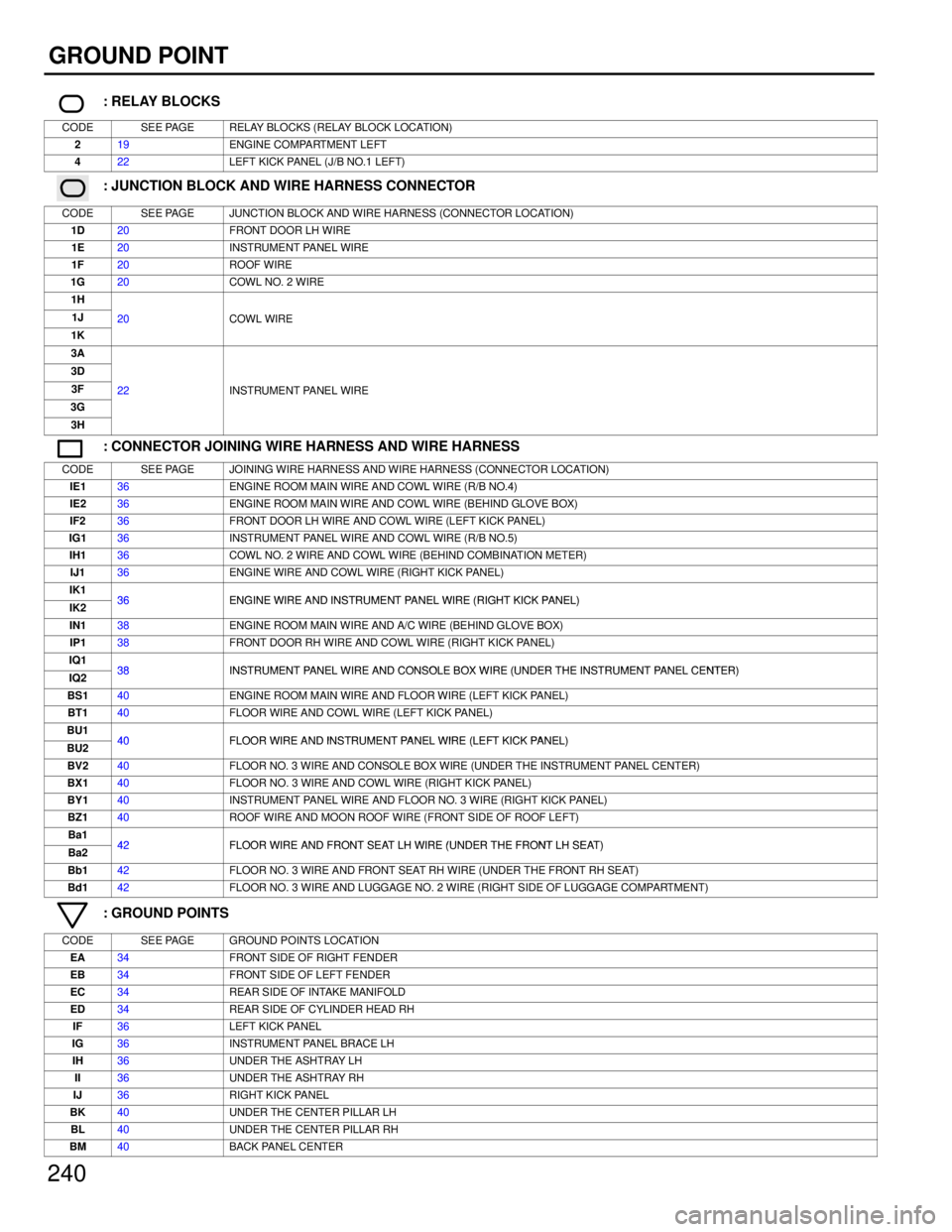
240
GROUND POINT
: RELAY BLOCKS
CODESEE PAGERELAY BLOCKS (RELAY BLOCK LOCATION)
219ENGINE COMPARTMENT LEFT
422LEFT KICK PANEL (J/B NO.1 LEFT)
: JUNCTION BLOCK AND WIRE HARNESS CONNECTOR
CODESEE PAGEJUNCTION BLOCK AND WIRE HARNESS (CONNECTOR LOCATION)
1D20FRONT DOOR LH WIRE
1E20INSTRUMENT PANEL WIRE
1F20ROOF WIRE
1G20COWL NO. 2 WIRE
1H
1J20COWL WIRE
1K
20COWL WIRE
3A
3D
3F22INSTRUMENT PANEL WIRE
3G
22INSTRUMENT PANEL WIRE
3H
: CONNECTOR JOINING WIRE HARNESS AND WIRE HARNESS
CODESEE PAGEJOINING WIRE HARNESS AND WIRE HARNESS (CONNECTOR LOCATION)
IE136ENGINE ROOM MAIN WIRE AND COWL WIRE (R/B NO.4)
IE236ENGINE ROOM MAIN WIRE AND COWL WIRE (BEHIND GLOVE BOX)
IF236FRONT DOOR LH WIRE AND COWL WIRE (LEFT KICK PANEL)
IG136INSTRUMENT PANEL WIRE AND COWL WIRE (R/B NO.5)
IH136COWL NO. 2 WIRE AND COWL WIRE (BEHIND COMBINATION METER)
IJ136ENGINE WIRE AND COWL WIRE (RIGHT KICK PANEL)
IK136ENGINE WIRE AND INSTRUMENT PANEL WIRE (RIGHT KICK PANEL)IK236ENGINE WIRE AND INSTRUMENT PANEL WIRE (RIGHT KICK PANEL)
IN138ENGINE ROOM MAIN WIRE AND A/C WIRE (BEHIND GLOVE BOX)
IP138FRONT DOOR RH WIRE AND COWL WIRE (RIGHT KICK PANEL)
IQ138INSTRUMENT PANEL WIRE AND CONSOLE BOX WIRE (UNDER THE INSTRUMENT PANEL CENTER)IQ238INSTRUMENT PANEL WIRE AND CONSOLE BOX WIRE (UNDER THE INSTRUMENT PANEL CENTER)
BS140ENGINE ROOM MAIN WIRE AND FLOOR WIRE (LEFT KICK PANEL)
BT140FLOOR WIRE AND COWL WIRE (LEFT KICK PANEL)
BU140FLOOR WIRE AND INSTRUMENT PANEL WIRE (LEFT KICK PANEL)BU240FLOOR WIRE AND INSTRUMENT PANEL WIRE (LEFT KICK PANEL)
BV240FLOOR NO. 3 WIRE AND CONSOLE BOX WIRE (UNDER THE INSTRUMENT PANEL CENTER)
BX140FLOOR NO. 3 WIRE AND COWL WIRE (RIGHT KICK PANEL)
BY140INSTRUMENT PANEL WIRE AND FLOOR NO. 3 WIRE (RIGHT KICK PANEL)
BZ140ROOF WIRE AND MOON ROOF WIRE (FRONT SIDE OF ROOF LEFT)
Ba142FLOOR WIRE AND FRONT SEAT LH WIRE (UNDER THE FRONT LH SEAT)Ba242FLOOR WIRE AND FRONT SEAT LH WIRE (UNDER THE FRONT LH SEAT)
Bb142FLOOR NO. 3 WIRE AND FRONT SEAT RH WIRE (UNDER THE FRONT RH SEAT)
Bd142FLOOR NO. 3 WIRE AND LUGGAGE NO. 2 WIRE (RIGHT SIDE OF LUGGAGE COMPARTMENT)
: GROUND POINTS
CODESEE PAGEGROUND POINTS LOCATION
EA34FRONT SIDE OF RIGHT FENDER
EB34FRONT SIDE OF LEFT FENDER
EC34REAR SIDE OF INTAKE MANIFOLD
ED34REAR SIDE OF CYLINDER HEAD RH
IF36LEFT KICK PANEL
IG36INSTRUMENT PANEL BRACE LH
IH36UNDER THE ASHTRAY LH
II36UNDER THE ASHTRAY RH
IJ36RIGHT KICK PANEL
BK40UNDER THE CENTER PILLAR LH
BL40UNDER THE CENTER PILLAR RH
BM40BACK PANEL CENTER
WhereEverybodyKnowsYourName
Page 3924 of 4087
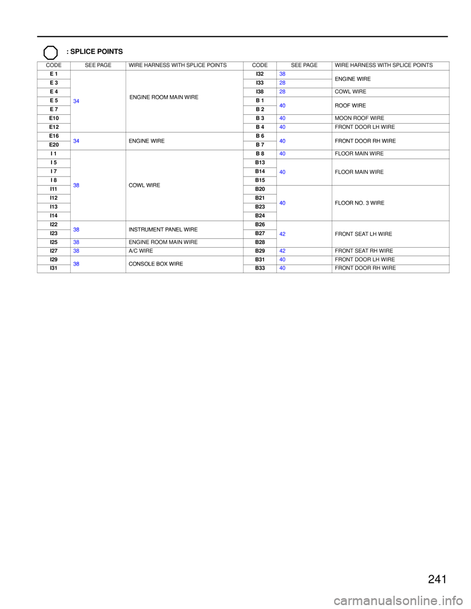
241
: SPLICE POINTS
CODESEE PAGEWIRE HARNESS WITH SPLICE POINTSCODESEE PAGEWIRE HARNESS WITH SPLICE POINTS
E 1I3238ENGINE WIREE 3I3328ENGINE WIRE
E 4ENGINE ROOM MAIN WIREI3828COWL WIRE
E 534ENGINE ROOM MAIN WIREB 140ROOF WIREE 7
34
B 240ROOF WIRE
E10B 340MOON ROOF WIRE
E12B 440FRONT DOOR LH WIRE
E1634ENGINE WIREB 640FRONT DOOR RH WIREE2034ENGINE WIREB 740FRONT DOOR RH WIRE
I 1B 840FLOOR MAIN WIRE
I 5B13
I 7B1440FLOOR MAIN WIRE
I 838COWL WIREB15
40FLOOR MAIN WIRE
I1138COWL WIREB20
I12B2140FLOOR NO 3 WIREI13B2340FLOOR NO. 3 WIRE
I14B24
I2238INSTRUMENT PANEL WIREB26
I2338INSTRUMENT PANEL WIREB2742FRONT SEAT LH WIRE
I2538ENGINE ROOM MAIN WIREB28
42FRONT SEAT LH WIRE
I2738A/C WIREB2942FRONT SEAT RH WIRE
I2938CONSOLE BOX WIREB3140FRONT DOOR LH WIRE
I3138CONSOLE BOX WIREB3340FRONT DOOR RH WIRE
WhereEverybodyKnowsYourName
Page 3925 of 4087
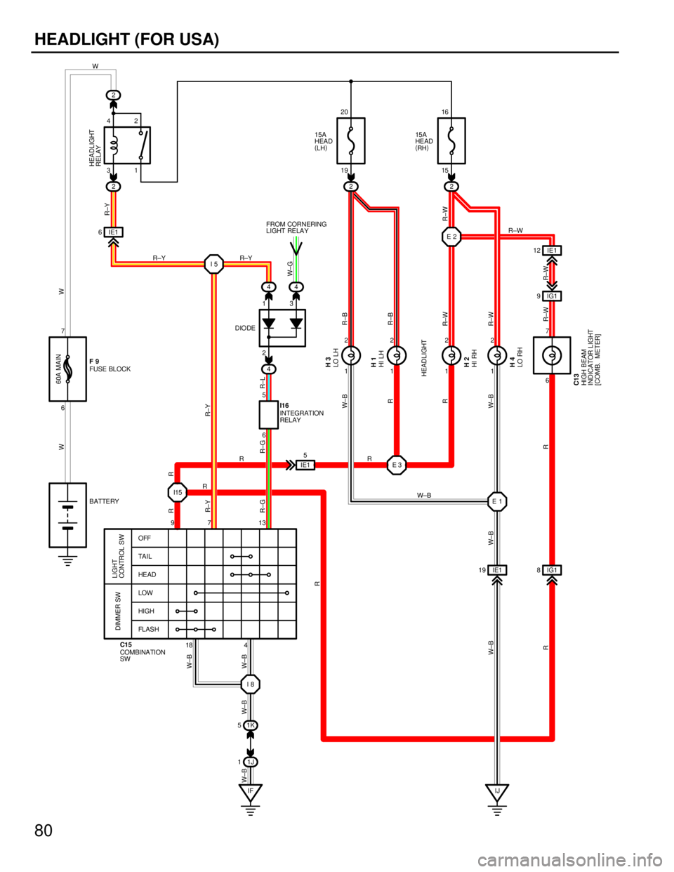
80
HEADLIGHT (FOR USA)
18
97 13
OFF
TA I L
HE AD
LOW
HIGH
FL AS H
LIGHT
CONTROL SW
DIMMER SW
COMBINATION
SW C15
1J
1
2
22
4
1K
5
2
1 21
2 1
21
2
IF
I8
I5
E2
E1
IJ
IE1
19 IG1 8
44
4
6 31 19 15
6
2
6 13
7
16
20
42
5
7
IG1
9
IE1
6
IE1
12
W
R±W
W
R±W
R±W R±W R±B
R±B
R±W
R±L
R±G R±Y
W
W±B
W±B
W±B
W±B
W±BR W±B
RR R
W±B
W±B
R±W
R±Y
W±G
60A MAIN
15A
HEAD
(
LH ) 15A
HE AD
(
RH )
FUSE BLOCK
HIGH BEAM
INDICATOR LIGHT
[COMB. METER]
INTEGRATION
RELAY
LO RH HI RH HI LH LO LH
BATTERY
HEADLIGHT
RELAY
FROM CORNERING
LIGHT RELAY I16
C13 H4 H2 H1 H3
F9
HEADLIGHT
DIODE
E3
I15 IE1
5
R±Y
R±Y
W±B
R
R
R
R
R R
R±Y
R±G
WhereEverybodyKnowsYourName
Page 3926 of 4087
X67
XXXX67
12 12 56
C13 C15
H1,H2 H3,H4 I16 BLACK
BLACK BROWN F9
X
X XX13 189
4
X7
X
81
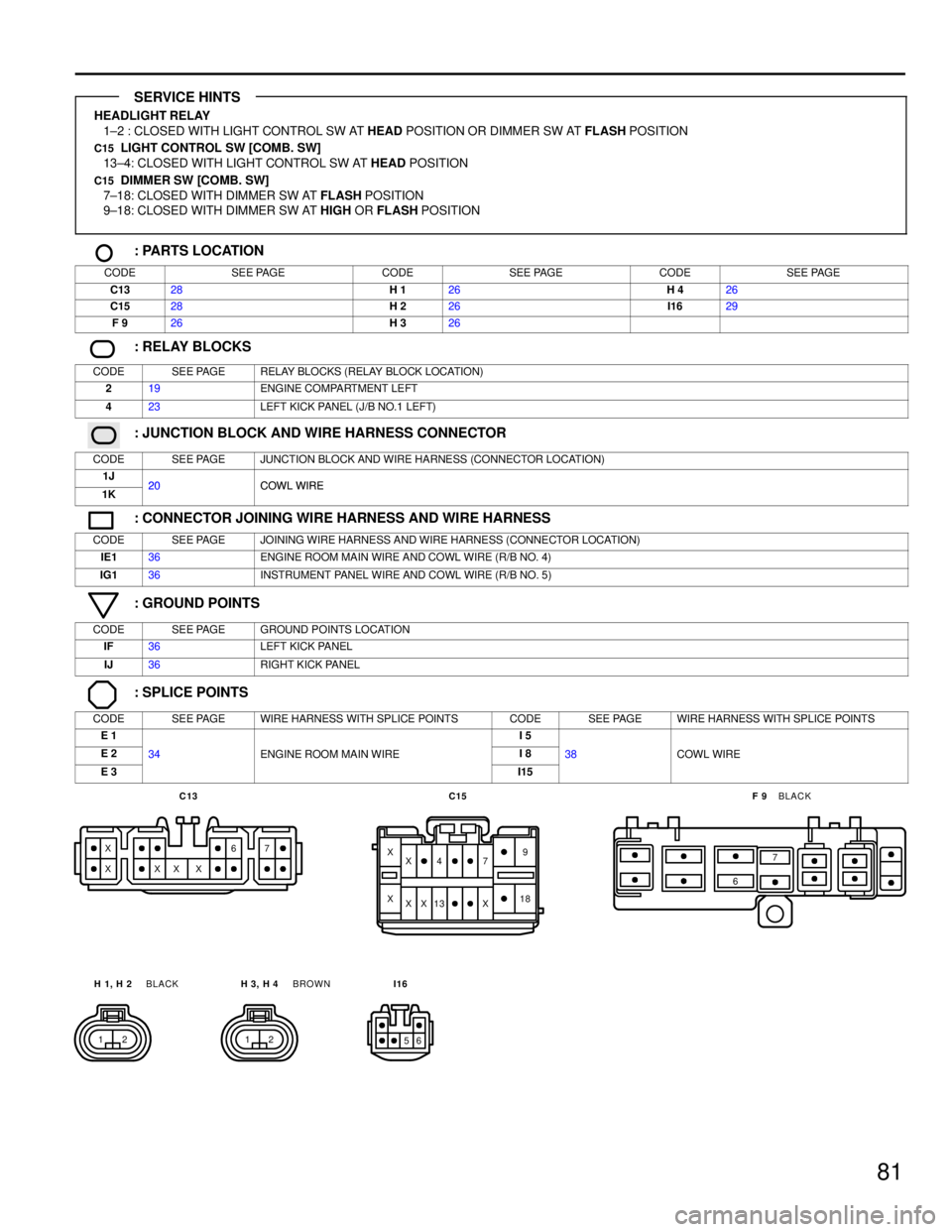
HEADLIGHT RELAY1±2 : CLOSED WITH LIGHT CONTROL SW AT HEAD POSITION OR DIMMER SW AT FLASH POSITION
C15 LIGHT CONTROL SW [COMB. SW]
13±4: CLOSED WITH LIGHT CONTROL SW AT HEAD POSITION
C15 DIMMER SW [COMB. SW]
7±18: CLOSED WITH DIMMER SW AT FLASH POSITION
9±18: CLOSED WITH DIMMER SW AT HIGH OR FLASH POSITION
: PARTS LOCATION
CODESEE PAGECODESEE PAGECODESEE PAGE
C1328H 126H 426
C1528H 226I1629
F 926H 326
: RELAY BLOCKS
CODESEE PAGERELAY BLOCKS (RELAY BLOCK LOCATION)
219ENGINE COMPARTMENT LEFT
423LEFT KICK PANEL (J/B NO.1 LEFT)
: JUNCTION BLOCK AND WIRE HARNESS CONNECTOR
CODESEE PAGEJUNCTION BLOCK AND WIRE HARNESS (CONNECTOR LOCATION)
1J20COWL WIRE1K20COWL WIRE
: CONNECTOR JOINING WIRE HARNESS AND WIRE HARNESS
CODESEE PAGEJOINING WIRE HARNESS AND WIRE HARNESS (CONNECTOR LOCATION)
IE136ENGINE ROOM MAIN WIRE AND COWL WIRE (R/B NO. 4)
IG136INSTRUMENT PANEL WIRE AND COWL WIRE (R/B NO. 5)
: GROUND POINTS
CODESEE PAGEGROUND POINTS LOCATION
IF36LEFT KICK PANEL
IJ36RIGHT KICK PANEL
: SPLICE POINTS
CODESEE PAGEWIRE HARNESS WITH SPLICE POINTSCODESEE PAGEWIRE HARNESS WITH SPLICE POINTS
E 1I 5
E 234ENGINE ROOM MAIN WIREI 838COWL WIRE
E 3I15
SERVICE HINTS
WhereEverybodyKnowsYourName
Page 3927 of 4087
![LEXUS SC400 1991 Service Repair Manual
1
C15 H 5, H 6 BLACK
X XX
X
14 X
X
111
HORN
2
5
IE19
4
44 IE 18
14 11E2
FROM POWER SOURCE SYSTEM
(
SEE PAGE 56 )
WW 25A
HAZ±HORN
HORN
RELAYBB
BG± R
B
12
6
HORN
HORN SW
[COMB. SW]
RH
LH
H5 H6
C15
3
LEXUS SC400 1991 Service Repair Manual
1
C15 H 5, H 6 BLACK
X XX
X
14 X
X
111
HORN
2
5
IE19
4
44 IE 18
14 11E2
FROM POWER SOURCE SYSTEM
(
SEE PAGE 56 )
WW 25A
HAZ±HORN
HORN
RELAYBB
BG± R
B
12
6
HORN
HORN SW
[COMB. SW]
RH
LH
H5 H6
C15
3](/img/36/57051/w960_57051-3926.png)
1
C15 H 5, H 6 BLACK
X XX
X
14 X
X
111
HORN
2
5
IE19
4
44 IE 18
14 11E2
FROM POWER SOURCE SYSTEM
(
SEE PAGE 56 )
WW 25A
HAZ±HORN
HORN
RELAYBB
BG± R
B
12
6
HORN
HORN SW
[COMB. SW]
RH
LH
H5 H6
C15
3
HORN RELAY
2±3 : CLOSED WITH HORN SW ON
: PARTS LOCATION
CODESEE PAGECODESEE PAGECODESEE PAGE
C1528H 526H 626
: RELAY BLOCKS
CODESEE PAGERELAY BLOCKS (RELAY BLOCK LOCATION)
219ENGINE COMPARTMENT LEFT
423LEFT KICK PANEL (J/B NO.1 LEFT)
: CONNECTOR JOINING WIRE HARNESS AND WIRE HARNESS
CODESEE PAGEJOINING WIRE HARNESS AND WIRE HARNESS (CONNECTOR LOCATION)
IE136ENGINE ROOM MAIN WIRE AND COWL WIRE (R/B NO.4)
: SPLICE POINTS
CODESEE PAGEWIRE HARNESS WITH SPLICE POINTSCODESEE PAGEWIRE HARNESS WITH SPLICE POINTS
E 234ENGINE ROOM MAIN WIRE
SERVICE HINTS
WhereEverybodyKnowsYourName
Page 3928 of 4087

3
HOW TO USE THIS MANUAL
This manual provides information on the electrical circuits in on vehicles b\
y dividing
them into a circuit for each system.
The actual wiring of each system circuit is shown from the point where the \
power source
is received from the battery as far as each ground point. (All circuit di\
agrams are shown
with the switches in the OFF position.)
When troubleshooting any problem, first understand the operation of the circ\
uit where
the problem was detected (see System Circuit section), the power source supplying
power to that circuit (see Power Source section), and the ground points (s\
ee Ground
Points section). See the System Outline to understand the circuit opera\
tion.
When the circuit operation is understood, begin troubleshooting of the probl\
em circuit
to isolate the cause. Use Relay Location and Electrical Routing sections t\
o find each
part, junction block and wiring harness connectors, wiring harness and wiring\
harness
connectors, splice points, and ground points of each system circuit. Internal wirin\
g for
each junction block is also provided for better understanding of connection \
within a
junction block.
Wiring related to each system is indicated in each system circuit by arrows (from
, to ). When overall connections are required, see the Overall Wiring Diagram
at the end of this manual.
WhereEverybodyKnowsYourName
Page 3929 of 4087
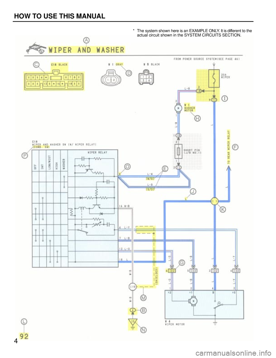
* The system shown here is an EXAMPLE ONLY. It is different to theactual circuit shown in the SYSTEM CIRCUITS SECTION.
4
HOW TO USE THIS MANUAL
WhereEverybodyKnowsYourName
Page 3930 of 4087
A
B
C
D
E
F
G
H
I
J
K
L
M
N
O
P
5
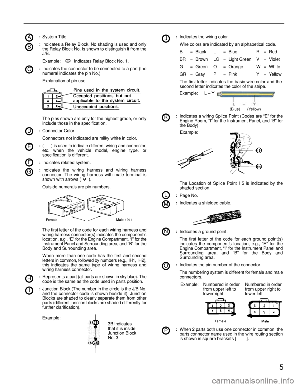
:System Title
: Indicates a Relay Block. No shading is used and only
the Relay Block No. is shown to distinguish it from the
J/B.
Example: Indicates Relay Block No. 1.
: Indicates the connector to be connected to a part (the
numeral indicates the pin No.)
Explanation of pin use.
The pins shown are only for the highest grade, or only
include those in the specification.
: Connector Color
Connectors not indicated are milky white in color.
: ( ) is used to indicate different wiring and connector,
etc. when the vehicle model, engine type, or
specification is different.
: Indicates related system.
: Indicates the wiring harness and wiring harness
connector. The wiring harness with male terminal is
shown with arrows ( ).
Outside numerals are pin numbers.
The first letter of the code for each wiring harness and
wiring harness connector(s) indicates the component's
location, e.g., ªEº for the Engine Compartment, ªIº for the
Instrument Panel and Surrounding area, and ªBº for the
Body and Surrounding area.
When more than one code has the first and second
letters in comm on, followed by numbers (e.g., IH1, IH2),
this indicates the same type of wiring harness and
wiring harness connector.
: Represents a part (all parts are shown in sky blue). The
code is the same as the code used in parts position.
: Junction Block (The number in the circle is the J/B No.
and the connector code is shown beside it). Junction
Blocks are shaded to clearly separate them from other
parts (different j unction blocks are shaded differently for
further clarification).
3B indicates
that it is inside
Junction Block
No. 3.
Example: :
Indicates the wiring color.
Wire colors are indicated by an alphabetical code.
B = Black L = Blue R = Red
BR = Brown LG = Light Green V = Violet
G = Green O = Orange W = White
GR = Gray P = Pink Y = Yellow
The first letter indicates the basic wire color and the
second letter indicates the color of the stripe.
Example: L ± Y
(Blue) (Yellow)
:Indicates a wiring Splice Point (Codes are ªEº for the
Engine Room, ªIº for the Instrument Panel, and ªBº for
the Body).
Example:
The Location of Splice Point I 5 is indicated by the
shaded section.
: Page No.
: Indicates a shielded cable.
:Indicates a ground point.
The first letter of the code for each ground point(s)
indicates the component's location, e.g., ªEº for the
Engine Compartment, ªIº for the Instrument Panel and
Surrounding area, and ªBº for the Body and
Surrounding area.
: Indicates the pin number of the connector.
The numbering system is different for female and male
connectors.
Example: Numbered in order from upper left to
lower right Numbered in order
from upper right to
lower left
:
When 2 parts both use one connector in common, the
parts connector name used in the wire routing section
is shown in square brackets [ ].
WhereEverybodyKnowsYourName