evap LEXUS SC400 1991 Service Manual PDF
[x] Cancel search | Manufacturer: LEXUS, Model Year: 1991, Model line: SC400, Model: LEXUS SC400 1991Pages: 4087, PDF Size: 75.75 MB
Page 2058 of 4087
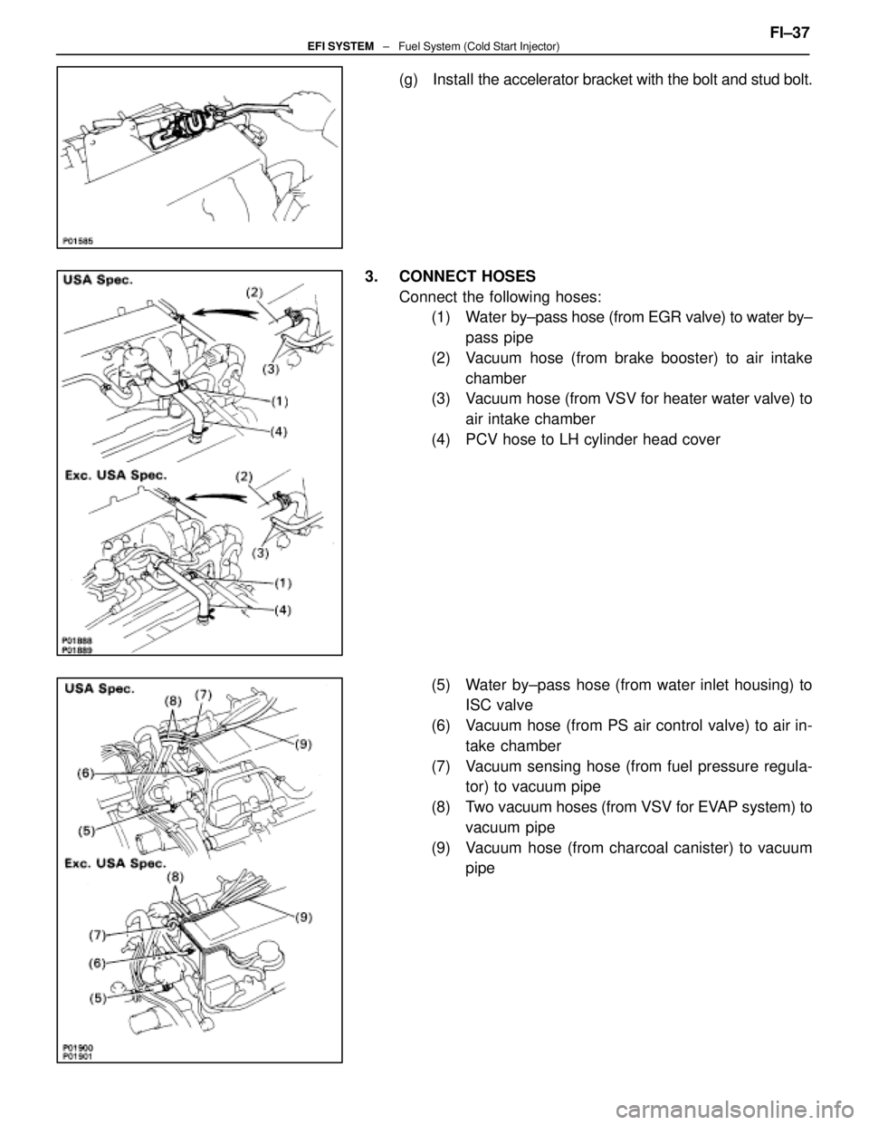
(g) Install the accelerator bracket with the bolt and stud bolt.
3. CONNECT HOSES Connect the following hoses:(1) Water by±pass hose (from EGR valve) to water by±
pass pipe
(2) Vacuum hose (from brake booster) to air intake chamber
(3) Vacuum hose (from VSV for heater water valve) to
air intake chamber
(4) PCV hose to LH cylinder head cover
(5) Water by±pass hose (from water inlet housing) to ISC valve
(6) Vacuum hose (from PS air control valve) to air in- take chamber
(7) Vacuum sensing hose (from fuel pressure regula- tor) to vacuum pipe
(8) Two vacuum hoses (from VSV for EVAP system) to
vacuum pipe
(9) Vacuum hose (from charcoal canister) to vacuum pipe FI±37
EFI SYSTEM
± Fuel System (Cold Start Injector)
WhereEverybodyKnowsYourName
Page 2061 of 4087

8. INSTALL VSV FOR EVAP SYSTEMInstall the VSV with the two bolts.
9. INSTALL LH NO.3 TIMING BELT COVER (a) Install the three gaskets to the timing belt cover.
(b) Install the cord grommet to the high±tension cord.
(c) Install the cord grommet to the timing belt cover.
(d) Fit portion A of the timing belt cover, matching it with the
lower high±tension cord cover.
(e) Install the timing belt cover with the four bolts.
10. INSTALL RH ENGINE WIRE COVER (a) Fit portions A and B of the engine wire cover, matching
them with the lower high±tension cord cover and No.3
timing belt cover.
(d) Install the engine wire cover with the bolt.
11. INSTALL LH ENGINE WIRE COVER (a) Connect portions A and B engine wire cover to the wirebrackets.
(b) Set the VSV (for fuel pressure control system) wire in original position.
(c) Fit portions C and D of the engine wire cover, matching them with the lower high±tension cord cover and No.3
timing belt cover.
(d) Install the engine wire cover with the two bolts.
12. INSTALL UPPER HIGH±TENSION CORD COVER (a) Fit portion A of the upper high±tension cover, matching
it with the top of the lower high±tension cord cover.
FI±40
EFI SYSTEM
± Fuel System (Cold Start Injector)
WhereEverybodyKnowsYourName
Page 2100 of 4087

6. REMOVE VSV FOR EVAP SYSTEMRemove the two bolts, and disconnect the VSV from cylinder
head and timing belt cover.
7. REMOVE RH NO.3 TIMING BELT COVER Remove the three bolts and timing belt cover.
8. REMOVE LH NO.3 TIMING BELT COVER (a) Remove the four mounting bolts.
(b) Disconnect the cord grommet from the timing belt cover,
and remove the timing belt cover.
(c) Remove the cord grommet from the high±tension cord.
9. REMOVE HIGH±TENSION CORDS (a) Disconnect the high±tension cords from the spark plugs
and distributor caps. Disconnect the high±tension cords
at the rubber boot. Do not pull on the cords.
NOTICE: Pulling on or bending the cords may damage
the conductor inside.
±
IGNITION SYSTEM High±Tension Cords and Cord ClampsIG±13
WhereEverybodyKnowsYourName
Page 2105 of 4087
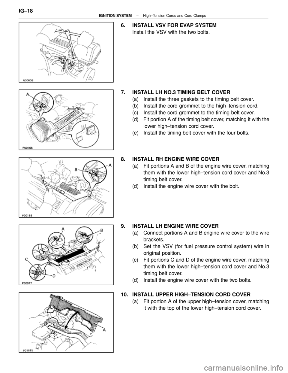
6. INSTALL VSV FOR EVAP SYSTEMInstall the VSV with the two bolts.
7. INSTALL LH NO.3 TIMING BELT COVER (a) Install the three gaskets to the timing belt cover.
(b) Install the cord grommet to the high±tension cord.
(c) Install the cord grommet to the timing belt cover.
(d) Fit portion A of the timing belt cover, matching it with the
lower high±tension cord cover.
(e) Install the timing belt cover with the four bolts.
8. INSTALL RH ENGINE WIRE COVER (a) Fit portions A and B of the engine wire cover, matchingthem with the lower high±tension cord cover and No.3
timing belt cover.
(d) Install the engine wire cover with the bolt.
9. INSTALL LH ENGINE WIRE COVER (a) Connect portions A and B engine wire cover to the wirebrackets.
(b) Set the VSV (for fuel pressure control system) wire in original position.
(c) Fit portions C and D of the engine wire cover, matching them with the lower high±tension cord cover and No.3
timing belt cover.
(d) Install the engine wire cover with the two bolts.
10. INSTALL UPPER HIGH±TENSION CORD COVER (a) Fit portion A of the upper high±tension cover, matchingit with the top of the lower high±tension cord cover.
IG±18
±
IGNITION SYSTEM High±Tension Cords and Cord Clamps
WhereEverybodyKnowsYourName
Page 2212 of 4087
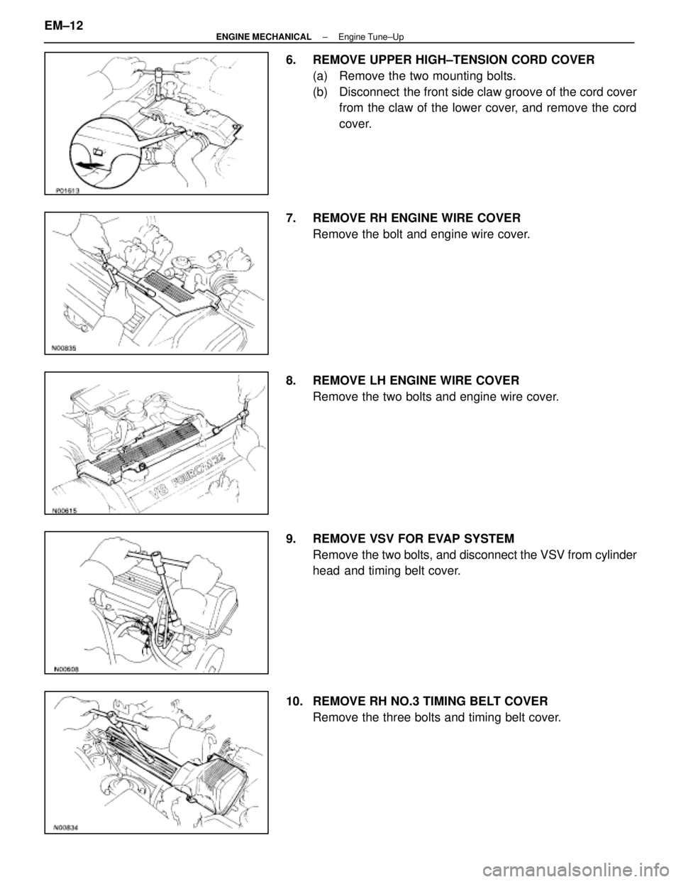
6. REMOVE UPPER HIGH±TENSION CORD COVER(a) Remove the two mounting bolts.
(b) Disconnect the front side claw groove of the cord coverfrom the claw of the lower cover, and remove the cord
cover.
7. REMOVE RH ENGINE WIRE COVER Remove the bolt and engine wire cover.
8. REMOVE LH ENGINE WIRE COVER Remove the two bolts and engine wire cover.
9. REMOVE VSV FOR EVAP SYSTEM Remove the two bolts, and disconnect the VSV from cylinder
head and timing belt cover.
10. REMOVE RH NO.3 TIMING BELT COVER Remove the three bolts and timing belt cover.
EM±12
±
ENGINE MECHANICAL Engine Tune±Up
WhereEverybodyKnowsYourName
Page 2225 of 4087
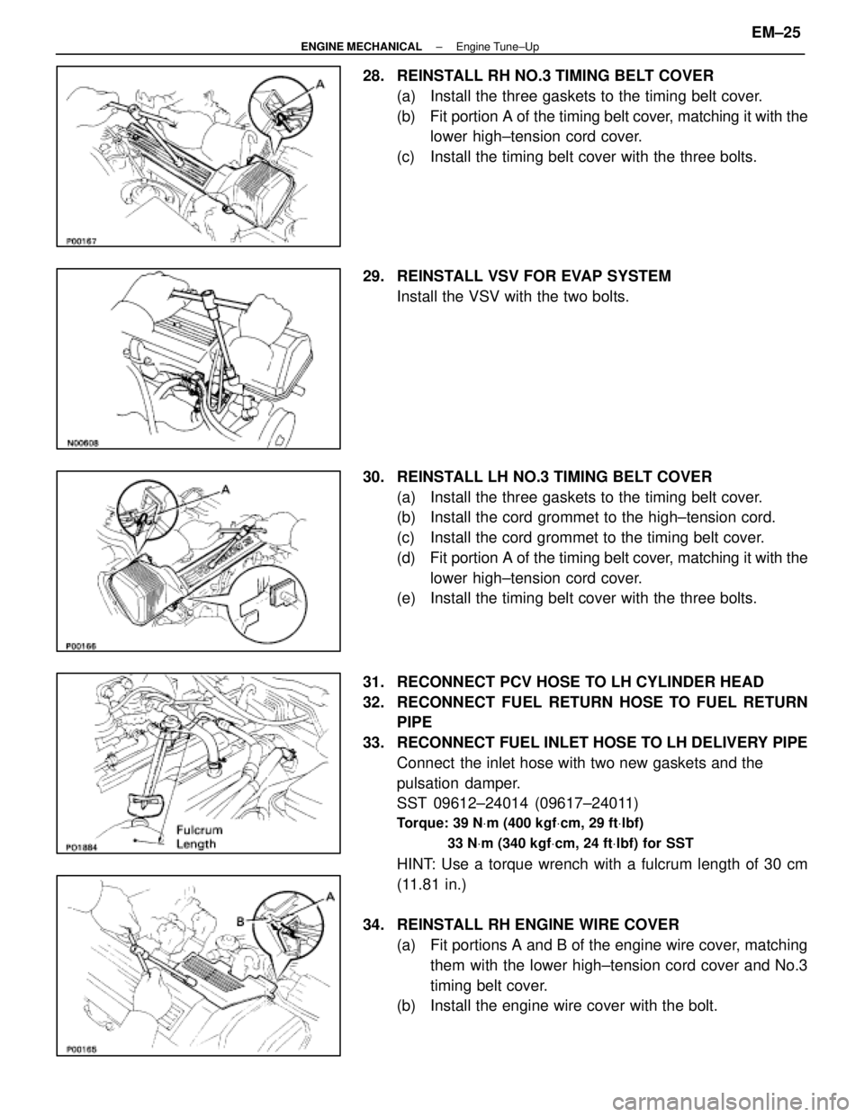
28. REINSTALL RH NO.3 TIMING BELT COVER(a) Install the three gaskets to the timing belt cover.
(b) Fit portion A of the timing belt cover, matching it with the
lower high±tension cord cover.
(c) Install the timing belt cover with the three bolts.
29. REINSTALL VSV FOR EVAP SYSTEM Install the VSV with the two bolts.
30. REINSTALL LH NO.3 TIMING BELT COVER (a) Install the three gaskets to the timing belt cover.
(b) Install the cord grommet to the high±tension cord.
(c) Install the cord grommet to the timing belt cover.
(d) Fit portion A of the timing belt cover, matching it with the
lower high±tension cord cover.
(e) Install the timing belt cover with the three bolts.
31. RECONNECT PCV HOSE TO LH CYLINDER HEAD
32. RECONNECT FUEL RETURN HOSE TO FUEL RETURN PIPE
33. RECONNECT FUEL INLET HOSE TO LH DELIVERY PIPE Connect the inlet hose with two new gaskets and the
pulsation damper.
SST 09612±24014 (09617±24011)
Torque: 39 N Vm (400 kgf Vcm, 29 ft Vlbf)
33 N Vm (340 kgf Vcm, 24 ft Vlbf) for SST
HINT: Use a torque wrench with a fulcrum length of 30 cm
(11.81 in.)
34. REINSTALL RH ENGINE WIRE COVER (a) Fit portions A and B of the engine wire cover, matchingthem with the lower high±tension cord cover and No.3
timing belt cover.
(b) Install the engine wire cover with the bolt.
±
ENGINE MECHANICAL Engine Tune±UpEM±25
WhereEverybodyKnowsYourName
Page 2237 of 4087
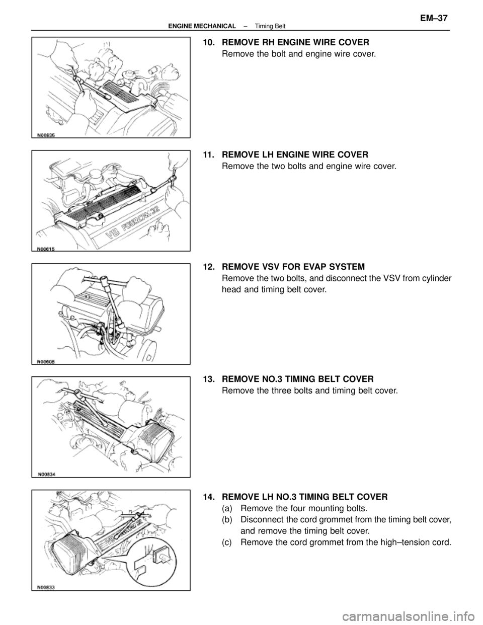
10. REMOVE RH ENGINE WIRE COVERRemove the bolt and engine wire cover.
11. REMOVE LH ENGINE WIRE COVER Remove the two bolts and engine wire cover.
12. REMOVE VSV FOR EVAP SYSTEM Remove the two bolts, and disconnect the VSV from cylinder
head and timing belt cover.
13. REMOVE NO.3 TIMING BELT COVER Remove the three bolts and timing belt cover.
14. REMOVE LH NO.3 TIMING BELT COVER (a) Remove the four mounting bolts.
(b) Disconnect the cord grommet from the timing belt cover,
and remove the timing belt cover.
(c) Remove the cord grommet from the high±tension cord.
±
ENGINE MECHANICAL Timing BeltEM±37
WhereEverybodyKnowsYourName
Page 2254 of 4087
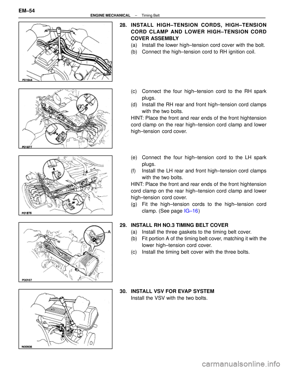
28. INSTALL HIGH±TENSION CORDS, HIGH±TENSIONCORD CLAMP AND LOWER HIGH±TENSION CORD
COVER ASSEMBLY
(a) Install the lower high±tension cord cover with the bolt.
(b) Connect the high±tension cord to RH ignition coil.
(c) Connect the four high±tension cord to the RH sparkplugs.
(d) Install the RH rear and front high±tension cord clamps
with the two bolts.
HINT: Place the front and rear ends of the front hightension
cord clamp on the rear high±tension cord clamp and lower
high±tension cord cover.
(e) Connect the four high±tension cord to the LH spark plugs.
(f) Install the LH rear and front high±tension cord clamps
with the two bolts.
HINT: Place the front and rear ends of the front hightension
cord clamp on the rear high±tension cord clamp and lower
high±tension cord cover.
(g) Fit the high±tension cords to the high±tension cord clamp. (See page IG±16)
29. INSTALL RH NO.3 TIMING BELT COVER (a) Install the three gaskets to the timing belt cover.
(b) Fit portion A of the timing belt cover, matching it with the
lower high±tension cord cover.
(c) Install the timing belt cover with the three bolts.
30. INSTALL VSV FOR EVAP SYSTEM Install the VSV with the two bolts.
EM±54
±
ENGINE MECHANICAL Timing Belt
WhereEverybodyKnowsYourName
Page 2262 of 4087
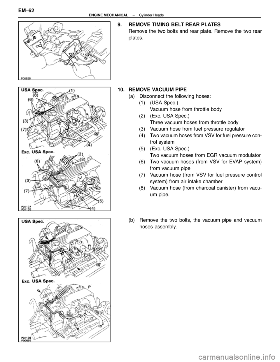
9. REMOVE TIMING BELT REAR PLATESRemove the two bolts and rear plate. Remove the two rear
plates.
10. REMOVE VACUUM PIPE (a) Disconnect the following hoses:(1) (USA Spec.)
Vacuum hose from throttle body
(2) (Exc. USA Spec.) Three vacuum hoses from throttle body
(3) Vacuum hose from fuel pressure regulator
(4) Two vacuum hoses from VSV for fuel pressure con-
trol system
(5) (Exc. USA Spec.) Two vacuum hoses from EGR vacuum modulator
(6) Two vacuum hoses (from VSV for EVAP system)
from vacuum pipe
(7) Vacuum hose (from VSV for fuel pressure control system) from air intake chamber
(8) Vacuum hose (from charcoal canister) from vacu-
um pipe.
(b) Remove the two bolts, the vacuum pipe and vacuum hoses assembly.
EM±62
±
ENGINE MECHANICAL Cylinder Heads
WhereEverybodyKnowsYourName
Page 2312 of 4087
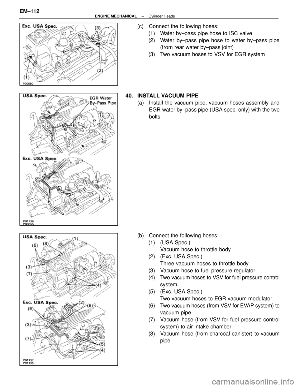
(c) Connect the following hoses:(1) Water by±pass pipe hose to ISC valve
(2) Water by±pass pipe hose to water by±pass pipe (from rear water by±pass joint)
(3) Two vacuum hoses to VSV for EGR system
40. INSTALL VACUUM PIPE (a) Install the vacuum pipe, vacuum hoses assembly andEGR water by±pass pipe (USA spec. only) with the two
bolts.
(b) Connect the following hoses: (1) (USA Spec.) Vacuum hose to throttle body
(2) (Exc. USA Spec.) Three vacuum hoses to throttle body
(3) Vacuum hose to fuel pressure regulator
(4) Two vacuum hoses to VSV for fuel pressure control system
(5) (Exc. USA Spec.) Two vacuum hoses to EGR vacuum modulator
(6) Two vacuum hoses (from VSV for EVAP system) to vacuum pipe
(7) Vacuum hose (from VSV for fuel pressure control system) to air intake chamber
(8) Vacuum hose (from charcoal canister) to vacuum pipe
EM±112
±
ENGINE MECHANICAL Cylinder Heads
WhereEverybodyKnowsYourName