high beam LEXUS SC400 1991 Service Repair Manual
[x] Cancel search | Manufacturer: LEXUS, Model Year: 1991, Model line: SC400, Model: LEXUS SC400 1991Pages: 4087, PDF Size: 75.75 MB
Page 507 of 4087
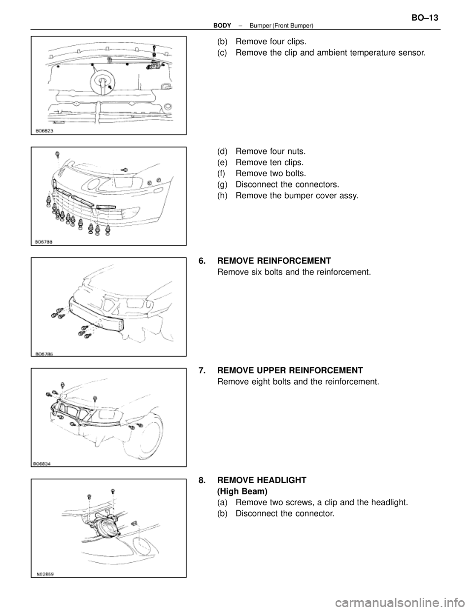
(b) Remove four clips.
(c) Remove the clip and ambient temperature sensor.
(d) Remove four nuts.
(e) Remove ten clips.
(f) Remove two bolts.
(g) Disconnect the connectors.
(h) Remove the bumper cover assy.
6. REMOVE REINFORCEMENT Remove six bolts and the reinforcement.
7. REMOVE UPPER REINFORCEMENT Remove eight bolts and the reinforcement.
8. REMOVE HEADLIGHT (High Beam)
(a) Remove two screws, a clip and the headlight.
(b) Disconnect the connector.
±
BODY Bumper (Front Bumper)BO±13
WhereEverybodyKnowsYourName
Page 833 of 4087
Parts Replacement ± Headlight
(Headlight)
REPLACEMENT OF HEADLIGHT
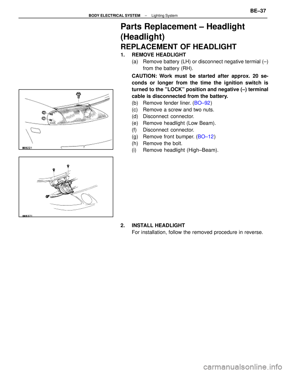
1. REMOVE HEADLIGHT(a) Remove battery (LH) or disconnect negative termial (±)from the battery (RH).
CAUTION: Work must be started after approx. 20 se-
conds or longer from the time the ignition switch is
turned to the ºLOCKº position and negative (±) terminal
cable is disconnected from the battery.
(b) Remove fender liner. ( BO±92)
(c) Remove a screw and two nuts.
(d) Disconnect connector.
(e) Remove headlight (Low Beam).
(f) Disconnect connector.
(g) Remove front bumper. ( BO±12)
(h) Remove the bolt.
(i) Remove headlight (High±Beam).
2. INSTALL HEADLIGHT For installation, follow the removed procedure in reverse.
±
BODY ELECTRICAL SYSTEM Lighting SystemBE±37
WhereEverybodyKnowsYourName
Page 843 of 4087
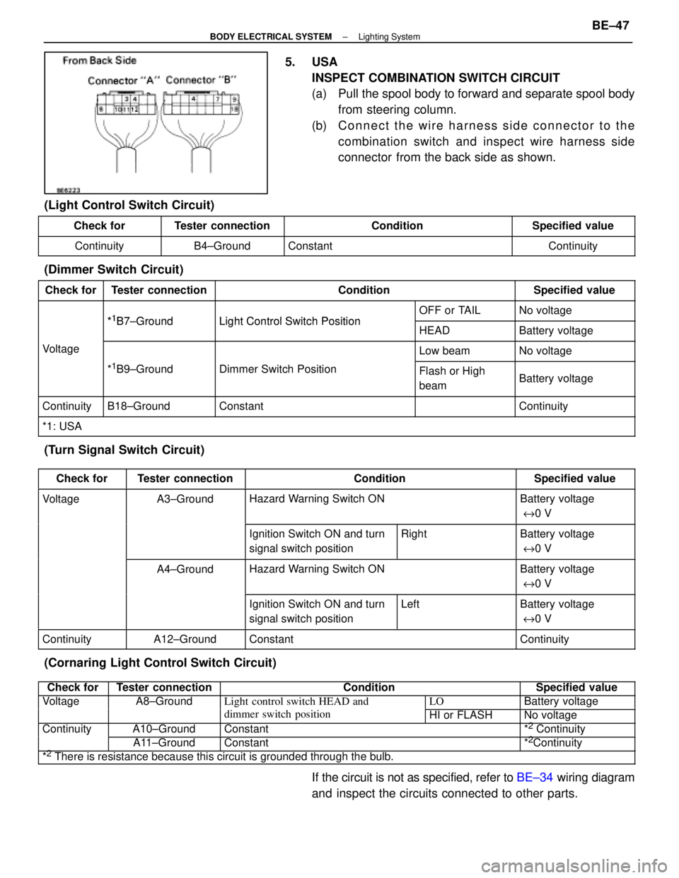
5. USAINSPECT COMBINATION SWITCH CIRCUIT
(a) Pull the spool body to forward and separate spool bodyfrom steering column.
(b) C onnect the wire harness side connector to the
combination switch and inspect wire harness side
connector from the back side as shown.
(Light Control Switch Circuit)
Check forTester connectionConditionSpecified value
ContinuityB4±GroundConstantContinuity
(Dimmer Switch Circuit)
Check forTester connectionConditionSpecified value
*1B7 GroundLight Control Switch PositionOFF or TAILNo voltage*1B7±GroundLight Control Switch PositionHEADBattery voltage
VoltageLow beamNo voltage
*1B9±GroundDimmer Switch PositionFlash or High
beamBattery voltage
ContinuityB18±GroundConstantContinuity
*1: USA
(Turn Signal Switch Circuit)
Check forTester connectionConditionSpecified value
VoltageA3±GroundHazard Warning Switch ONBattery voltage
e 0 V
Ignition Switch ON and turn
signal switch positionRightBattery voltage
e 0 V
A4±GroundHazard Warning Switch ONBattery voltage
e 0 V
Ignition Switch ON and turn
signal switch positionLeftBattery voltage
e 0 V
ContinuityA12±GroundConstantContinuity
(Cornaring Light Control Switch Circuit)
Check forTester connectionConditionSpecified value
VoltageA8±GroundLight control switch HEAD andLOBattery voltagegg
dimmer switch positionHI or FLASHNo voltage
ContinuityA10±GroundConstant*2 Continuityy
A11±GroundConstant*2Continuity
*2 There is resistance because this circuit is grounded through the bulb.
If the circuit is not as specified, refer to BE±34 wiring diagram
and inspect the circuits connected to other parts.
±
BODY ELECTRICAL SYSTEM Lighting SystemBE±47
WhereEverybodyKnowsYourName
Page 846 of 4087

(Canada)
Check forTester connectionConditionSpecified value
ContinuityA4±GroundPassenger's CourtesyOFFNo continuityygy
ONContinuity
A5±GroundIgnition KeyPull offNo continuitygy
Put inContinuity
A6±GroundDriver's CourtesyOFFNo continuityy
ONContinuity
A8±GroundSeat BeltUnfastenContinuity
FastenNo continuity
A10±GroundConstantContinuity
A12±GroundConstantContinuity
B1±GroundPassenger's DoorUnlockContinuityg
LockNo continuity
B2±GroundParking Brake
Switch PositionOFF (Switch pin
pushed in)No continuity
ON (Switch pin re-
leased)Continuity
B3±GroundDriver's DoorUnlockContinuity
LockNo continuity
B7±GroundHeadlight Dimmer
Switch PositionLow Beam or High
BeamNo continuity
FlashContinuity
B8±GroundHeadlight DimmerLow BeamNo continuityg
Switch PositionHigh Beam or FlashContinuity
B10±GroundLight Control SwitchOFFNo continuityg
HEAD or TAILContinuity
B12±GroundConstantContinuity
B13±GroundLight Control SwitchOFF or TAILNo continuityg
HEADContinuity
VoltageA1±GroundConstantVoltageg
A2±GroundConstant*Voltage
A7±GroundIgnition SwitchONVoltageg
LOCK or ACCNo voltage
A9±GroundIgnition SwitchON*Voltageg
LOCK or ACCNo voltage
A11±GroundIgnition SwitchON or ACCVoltageg
LOCKNo voltage
B4±GroundEngineSTOPNo voltageg
RunningVoltage
B11±GroundConstantVoltage
* There is resistance because this circuit is grounded through the bulb.\
If the circuit is as specified, trying replacing the relay with a
new one.
If the circuit is not as specified, refer to BE±35 wiring diagram
and inspect the circuit connected to other parts.
BE±50
±
BODY ELECTRICAL SYSTEM Light System
WhereEverybodyKnowsYourName
Page 1140 of 4087

8. INSPECT CHARGING CIRCUIT WITH LOAD(a) With the engine running at 2,000 rpm, turn on the highbeam headlights and place the heater blower switch at
ºHIº.
(b) Check the reading on the ammeter.
Standard amperage: 30 A or more
If the ammeter reading is less than standard amperage, re-
pair the alternator. (See page CH±9)
HINT: With the battery fully charged, the indication will some-
times be less than standard amperage.
9. REINSTALL ENGINE UNDER COVER
CH±8
±
CHARGING SYSTEM On±Vehicle Inspection
WhereEverybodyKnowsYourName
Page 2772 of 4087
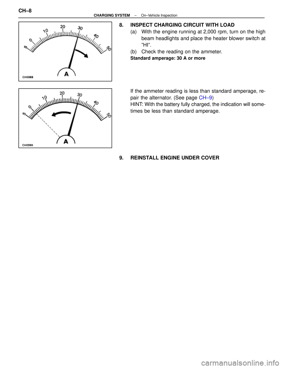
8. INSPECT CHARGING CIRCUIT WITH LOAD(a) With the engine running at 2,000 rpm, turn on the highbeam headlights and place the heater blower switch at
ºHIº.
(b) Check the reading on the ammeter.
Standard amperage: 30 A or more
If the ammeter reading is less than standard amperage, re-
pair the alternator. (See page CH±9)
HINT: With the battery fully charged, the indication will some-
times be less than standard amperage.
9. REINSTALL ENGINE UNDER COVER
CH±8
±
CHARGING SYSTEM On±Vehicle Inspection
WhereEverybodyKnowsYourName
Page 3860 of 4087
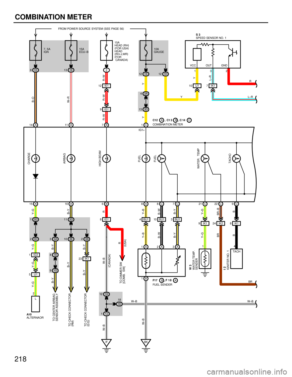
218COMBINATION METER
1E
81E 13
1E
12 1H 12
1J
1
3D
23A 3
3D
13D 11
1E
4
1G
9
1K
12
1E18 3D
13 3A
4
IG1
8BU1 4BU110 BU1 3
IG3
1 IK1
8
IK1
9IK2 24
IJ 1
5 1
IF BK
A
14 A 11 C 1
A
15 A 10 B 6A 8C8C 7C 9
C
21 C 22
132
L±R
FROM POWER SOURCE SYSTEM
(
SEE PAGE 56 )
4
Y
W±B W±B
B±O
W±R
YYY
Y±G Y±G Y±G Y±G B±Y
R
Y±B
B±W B±Y
B
Y±G
BR±B
BR
Y±G
B
B±Y
B±W Y±B
W±B B±Y
B±Y
W±B W±B
10A
GAUGE
15A
ECU±B
7. 5A
IGN
FUEL SENDER
IGNITER NO. 1 WATER TEMP.
SENDER
A
1A 2A 3
B
1 COMBINATION METER
TO CENTE R AIRB AG
SENSOR ASSEMBLY
TA CH
C12 , C1 3 , C 14
F1 7 ,
F18
I2 W3
ABC
B A SPEED SENSOR NO. 1
CHARGE
AIRBAG
HIGH BEAM
FUEL
FUEL
WATER. TEMP TACHO
S3
VCC OUT GND
2
B
7
R±W
15A
HEAD (
RH )
( FOR USA )
HEAD
( RH±LWR )
( FOR
CA NADA )
3B
2
B±Y
B±Y
TO CHECK CONNECTOR
( E/G )
3E
10
B±Y
TO CHECK CONNECTOR
( RM )
IK1
23
R
(
CANADA )
(USA )
TO DIMMER SW
[COMB. SW] R±W
IG1
9
IG1+ R
L±R
IK1
7
2 L
ALTERNAOR BR
IE1
12
R±W
IJ1
10
A1 0
WhereEverybodyKnowsYourName
Page 3920 of 4087
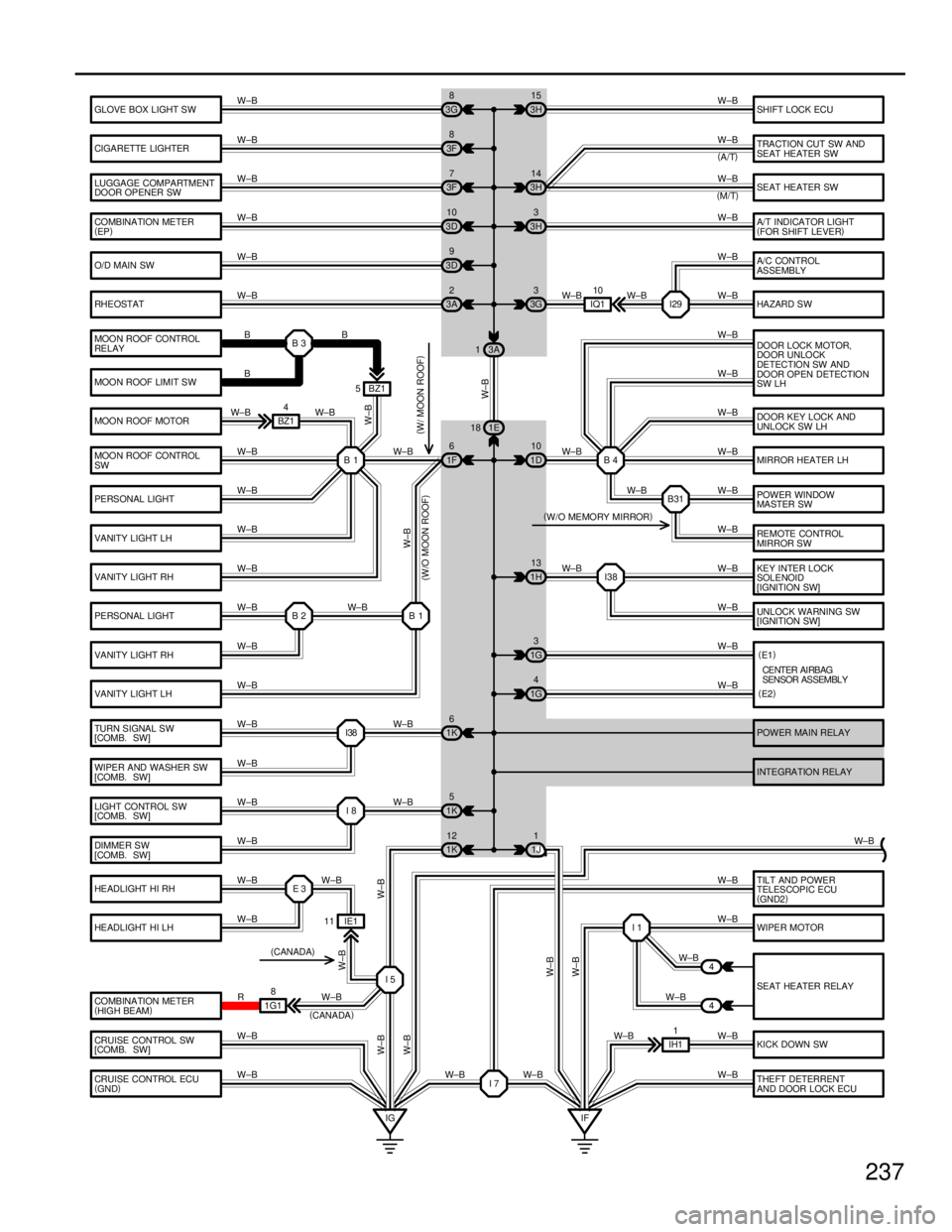
237
GLOVE BOX LIGHT SW
CIGARETTE LIGHTER
LUGGAGE COMPARTMENT
DOOR OPENER SW
COMBINATION METER
(EP )
O/D MAIN SW
RHEOSTAT
DO OR LOCK MOTOR,
DOOR UNLOCK
DETECTION SW AND
DOOR OPEN DETECTION
SW LH
MIRROR HEATER LH DOOR KEY LOCK AND
UNLOCK SW LH
POWER WINDOW
MASTER SW
RE MOTE CO NTROL
MIRROR SW
KEY INTER LOCK
SOLENOID
[IGNITION SW]
UNLOCK WA RNING SW
[IGNITION SW]
TURN SIGNAL SW
[COMB. SW]
WIPER AND WASHER SW
[COMB. SW]
LIGHT CONTROL SW
[COMB. SW]
DIMMER SW
[COMB. SW] INTEGRATION RELAY POWER MAIN RELAY HA ZARD S W A/C CONTROL
ASSEMBLY A/T INDICATOR LIGHT
(
FOR SHIFT LEVER )
SEAT HEATER SW TRACTION CUT SW AND
SEAT HEATER SW SHIFT LOCK ECU
3G 8
3F 8
3F 7
3D 10
3D 9
3A 2
1F 6
1K 6 3H
15
3H 14
3H 3
1D 10
1G 3
1G 4
IF
IG 1E
18 3A
1
W±B W±B W±B
W±B
W±B
W±B W±B W±B
W±B W±B
W±B W±B W±B W±B
W±B W±B
W±B W±B
W±B
W±B
W±B
CE NTER AI RB AG
SENSOR ASSEMBLY
I29
W±B
W±B
3G
3
I38 I8 1K 5
WIPER MOTOR
SEAT HEATER RELAY
KICK DOWN SW
THEFT DETERRENT
AND DOOR LOCK ECU
HE ADLIGHT HI RH
HE ADLIGHT HI LH
COMBINATION METER
(
HIGH BEAM )
CRUISE CONTROL SW
[COMB. SW] E3
I1
4
4
1K
12
IE1
11
IH11
CRUISE CONTROL ECU
( GND ) 1J
1
I7
1G1
8
I5 W±B
W±B
W±B
W±B
W±B
W±B
W±B
W±B R
W±B
W±B W±B W±B W±B W±BW±BW±B
W±B W±B W±B
W±B W±B
W±B
W±B
W±B
W±B
W±B W±B
W±B
W±B
IQ1 10
W±B
(E1 )
( E2 )
TILT AND POWER
TELESCOPIC ECU
( GND2 )
W±B ( A/T )
( M/T )
W±B
1H 13
I38
B4
B31
MOO N ROOF CO NTROL
RE LAY
MOON ROOF LIMIT SW
MOO N ROOF MOTOR
MOO N ROOF CO NTROL
SW
PERSONAL LIGHT
VANITY LIGHT LH
VANITY LIGHT RH
PERSONAL LIGHT
VANITY LIGHT RH
VANITY LIGHT LH B3
B1
B1
B2
B
W±B B
W±B
W±B
W±B
W±B
W±B
W±B
W±B W±BW±B
BZ1
4 BZ1
5
B
W±B
W±B
( CANADA )
W±B
( W/O MOON ROOF )(
W/ MOON ROOF )
(
W/O MEMORY MIRROR )
W±B
(
CANADA )
WhereEverybodyKnowsYourName
Page 3925 of 4087
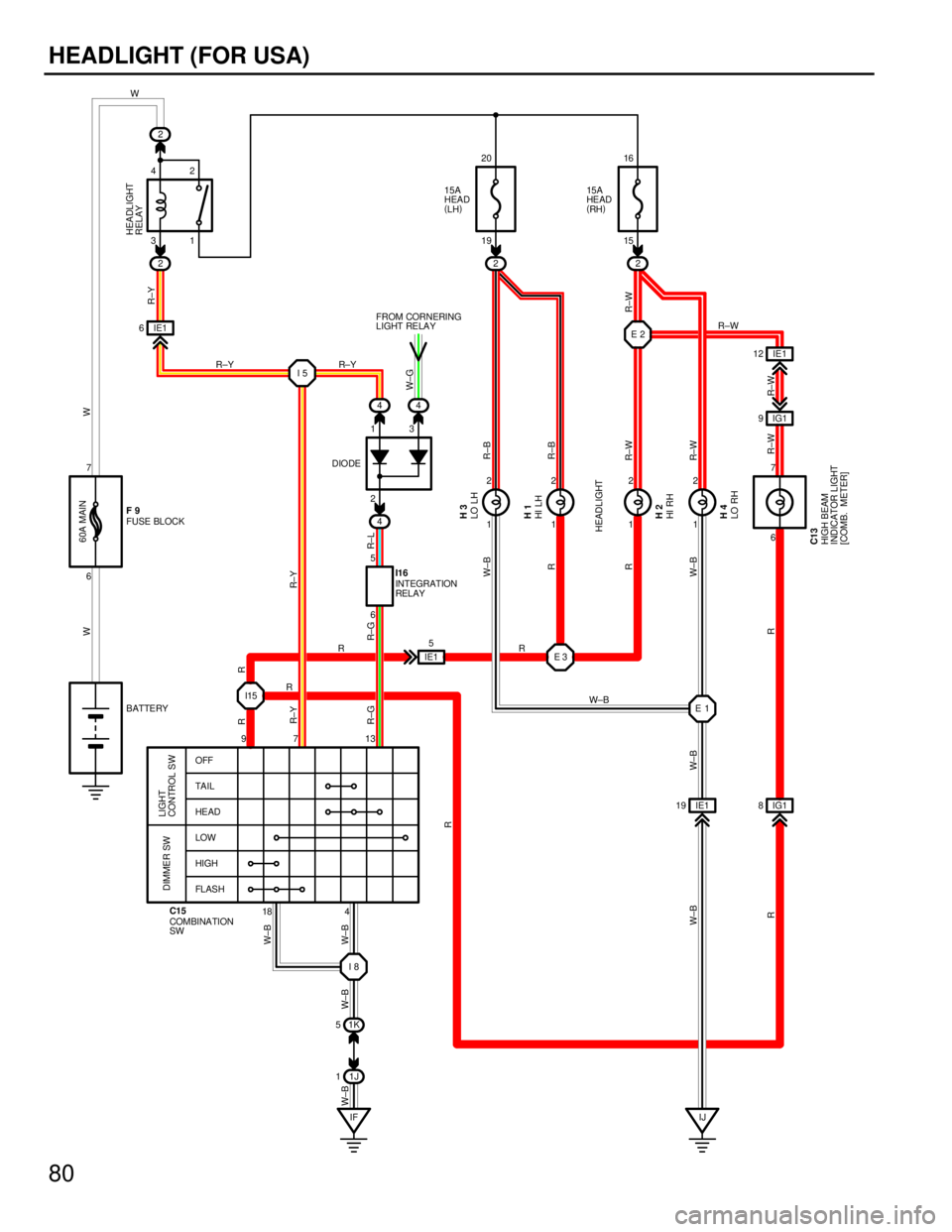
80
HEADLIGHT (FOR USA)
18
97 13
OFF
TA I L
HE AD
LOW
HIGH
FL AS H
LIGHT
CONTROL SW
DIMMER SW
COMBINATION
SW C15
1J
1
2
22
4
1K
5
2
1 21
2 1
21
2
IF
I8
I5
E2
E1
IJ
IE1
19 IG1 8
44
4
6 31 19 15
6
2
6 13
7
16
20
42
5
7
IG1
9
IE1
6
IE1
12
W
R±W
W
R±W
R±W R±W R±B
R±B
R±W
R±L
R±G R±Y
W
W±B
W±B
W±B
W±B
W±BR W±B
RR R
W±B
W±B
R±W
R±Y
W±G
60A MAIN
15A
HEAD
(
LH ) 15A
HE AD
(
RH )
FUSE BLOCK
HIGH BEAM
INDICATOR LIGHT
[COMB. METER]
INTEGRATION
RELAY
LO RH HI RH HI LH LO LH
BATTERY
HEADLIGHT
RELAY
FROM CORNERING
LIGHT RELAY I16
C13 H4 H2 H1 H3
F9
HEADLIGHT
DIODE
E3
I15 IE1
5
R±Y
R±Y
W±B
R
R
R
R
R R
R±Y
R±G
WhereEverybodyKnowsYourName
Page 3959 of 4087
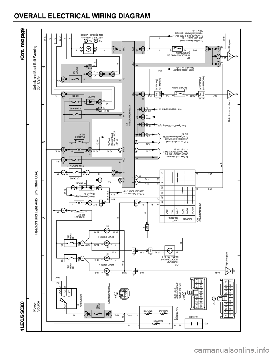
OVERALL ELECTRICAL WIRING DIAGRAM
1234
4 LEXUS SC300
1J
7 221J
81B2
4
1B
5
1B
4 1K
11
22
22
44
1I 1E
3
4
1 2 23
1
5
4
ACC
IG1
ST1
AM1 3
2
1 21
2 1
21
2
19 IE1 12 IE1 5IE1 6IE1
9IG1
4
7
6 4
19 15
1
3 20 16
2
18 4
97 313
6 7
IJ 1J
5
3A 1E 1C
1A
1I
15
1C
1F
1K 3D
7B 1A
2 1 9
10
BK IF 1H
1K 1J 1E W± BY Y
G± O G
G
W± L
Y
Y
W± B
R± Y
W± G
G± W
W± LW± L
W± L W
W± B R± W
W± B
R
L±W P± B
G±L
R± W
R± W
BR± W
B±L
B±L
W±B
W± B
W±B W±B W±B
W±B W±B
R± W
R± W
R± WR± W
R± W R±B R±B
W
G± W
G± W W
P±L
W± L
G G
P±L
B±Y
W
R± Y R±L R
YVPower
Source
F9
FUSE BL OCK60A MAIN 100A AM1
120A ALT
W
R±Y
40A
IGSW
LO
HI
HI
LO
HEADLIGHT LH
HEADLIGHT RH
HEADLIGHT
RELAY
Fr om Connerring Light
Relay< 7±2> DI ODE10A DOME
7. 5A RADIO No. 2
LIGHT
CONTROL
DIMMER
OFF
TAIL
HEAD
LOW
HIGH
FLASH HU HF FL E D T H E L
C15
COMBINATI ON SW
BATTERY
C13
HIGH BEAM
I NDI CA TOR L I GHT
[COMB. METER]
To Door Lock Mot or and
Unlock Detection SW and
Doo r Open De t ect i on S W LH
<17±5><17±6>
To Door Lock Mot or and
Unlock Detection SW and
Doo r Open De t ect i on S W RH
< 17±6>
From Open Door War ning Light
From Per sonal Light< 6±2>
B4
BACKLE SW LH
I15
UNLOCK WARNI NG SW
[IGNITION SW] SEAT BELT WARNI NG
LI GHT[ COMB. MET ER]
5118
TAIL LIGHT
RELAY
To Thef t
Deter rent and
Do or L oc k ECU
< 17±3>
7. 5A PANEL15A TAIL
10A
GAUGE
3 12 2
13 4Y
BELT
H± LP B A CC TRLY I NTB I G
BKL KEY
12 12
9
To Theft Deterr ent and
Door Lock ECU< 17±3>
I15
IGNITION SW
I16
I NTEGRAT I ON REL AY
H
T
G± L
R±G
1 3
2
B±Y
G±O
1C
16DI ODE
1E
1
9
C1 2 , C1 4 AB
6
From Tens ion Reducer
Solenoid LH< 11±7>
Fr om Thef t Deter rent and
Door Loc k ECU< 17±2>
Fr om Day /Night Shift SW< 12±1>
Fr om Tilt and Power Teles copic
ECU< 11±1> Y
Y
B±L
W±B
5C 4C
CC 3 111 12 7
6428 510 GND
INTEGRATI ON RELAY
SEAT BELT
WARNING LIGHT
[COMB. METER]12
3456
10 11 12 13 17 18 19 20 21 12345 6789
14 15 16
17 18
1 2345 6789 10
23
22
21
20
19
15
14
13
12
11 16 C
A
B I16
C12
C1 4
Headlight and Light Auto Turn Off (
for USA ) Unlock and Seat Belt Warning
(
for USA )
(
Cont . ne xt pa ge )
2
1
1I 3
R± YR± Y
C6 C
21
Y
Right kic k panel
Under t he c ent er pillar LH Left k ick panel
IG1
8
15A
HEAD
RH
15A
HE AD
LH
W±B R
R
R
R
R
R 6Ba2
Ba1
11
5Ba2 Ba1
12 (
w/ ME MORY )
( w/ o MEMORY )
(
w/ Me mo r y )
( w/ o Memory )
WhereEverybodyKnowsYourName