rear lift gate LINCOLN AVIATOR 2004 Owners Manual
[x] Cancel search | Manufacturer: LINCOLN, Model Year: 2004, Model line: AVIATOR, Model: LINCOLN AVIATOR 2004Pages: 336, PDF Size: 3.69 MB
Page 89 of 336
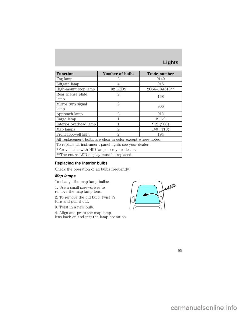
Function Number of bulbs Trade number
Fog lamp 2 9140
Liftgate lamp 4 916
High-mount stop lamp 32 LEDS 2C54±13A613**
Rear license plate
lamp2
168
Mirror turn signal
lamp2
906
Approach lamp 2 912
Cargo lamp 1 211-2
Interior overhead lamp 1 912 (906)
Map lamps 2 168 (T10)
Front footwell light 2 194
All replacement bulbs are clear in color except where noted.
To replace all instrument panel lights see your dealer.
*For vehicles with HID lamps see your dealer.
**The entire LED display must be replaced.
Replacing the interior bulbs
Check the operation of all bulbs frequently.
Map lamps
To change the map lamp bulbs:
1. Use a small screwdriver to
remove the map lamp lens.
2. To remove the old bulb, twist
1¤4
turn and pull it out.
3. Twist in a new bulb.
4. Align and press the map lamp
lens back on and test the lamp operation.
Lights
89
Page 90 of 336
Liftgate lamps
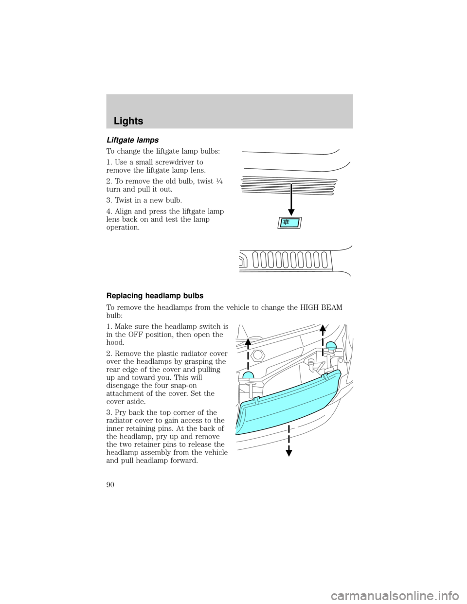
To change the liftgate lamp bulbs:
1. Use a small screwdriver to
remove the liftgate lamp lens.
2. To remove the old bulb, twist
1¤4
turn and pull it out.
3. Twist in a new bulb.
4. Align and press the liftgate lamp
lens back on and test the lamp
operation.
Replacing headlamp bulbs
To remove the headlamps from the vehicle to change the HIGH BEAM
bulb:
1. Make sure the headlamp switch is
in the OFF position, then open the
hood.
2. Remove the plastic radiator cover
over the headlamps by grasping the
rear edge of the cover and pulling
up and toward you. This will
disengage the four snap-on
attachment of the cover. Set the
cover aside.
3. Pry back the top corner of the
radiator cover to gain access to the
inner retaining pins. At the back of
the headlamp, pry up and remove
the two retainer pins to release the
headlamp assembly from the vehicle
and pull headlamp forward.
Lights
90
Page 94 of 336
Replacing tail/brake/turn/sidemarker/backup lamp bulbs
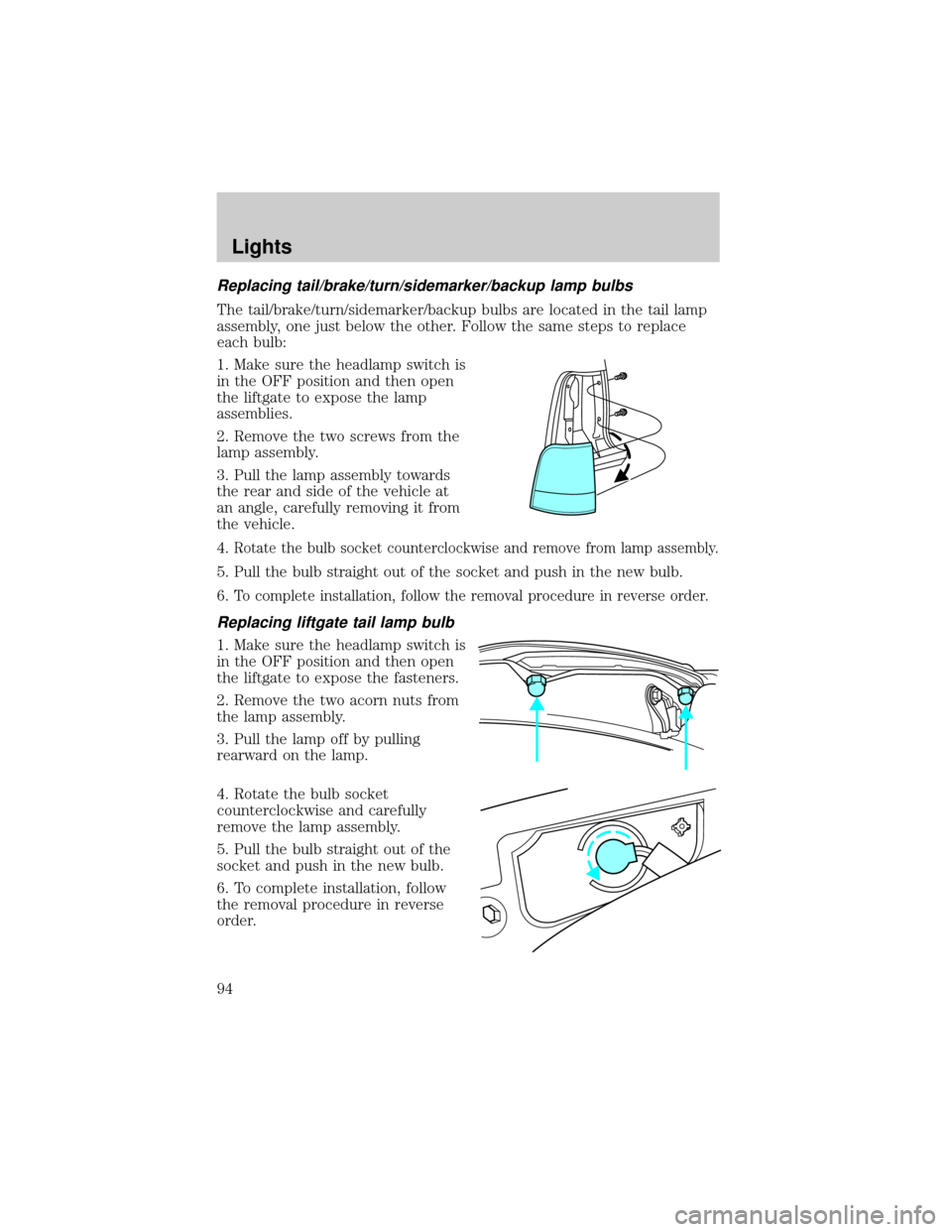
The tail/brake/turn/sidemarker/backup bulbs are located in the tail lamp
assembly, one just below the other. Follow the same steps to replace
each bulb:
1. Make sure the headlamp switch is
in the OFF position and then open
the liftgate to expose the lamp
assemblies.
2. Remove the two screws from the
lamp assembly.
3. Pull the lamp assembly towards
the rear and side of the vehicle at
an angle, carefully removing it from
the vehicle.
4.
Rotate the bulb socket counterclockwise and remove from lamp assembly.
5. Pull the bulb straight out of the socket and push in the new bulb.
6.
To complete installation, follow the removal procedure in reverse order.
Replacing liftgate tail lamp bulb
1. Make sure the headlamp switch is
in the OFF position and then open
the liftgate to expose the fasteners.
2. Remove the two acorn nuts from
the lamp assembly.
3. Pull the lamp off by pulling
rearward on the lamp.
4. Rotate the bulb socket
counterclockwise and carefully
remove the lamp assembly.
5. Pull the bulb straight out of the
socket and push in the new bulb.
6. To complete installation, follow
the removal procedure in reverse
order.
Lights
94
Page 102 of 336
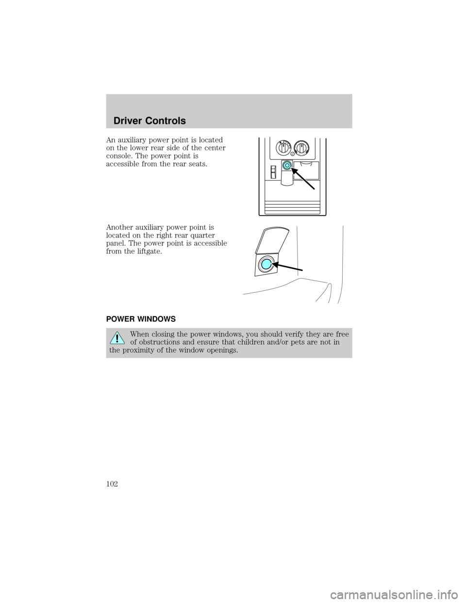
An auxiliary power point is located
on the lower rear side of the center
console. The power point is
accessible from the rear seats.
Another auxiliary power point is
located on the right rear quarter
panel. The power point is accessible
from the liftgate.
POWER WINDOWS
When closing the power windows, you should verify they are free
of obstructions and ensure that children and/or pets are not in
the proximity of the window openings.
Driver Controls
102
Page 133 of 336
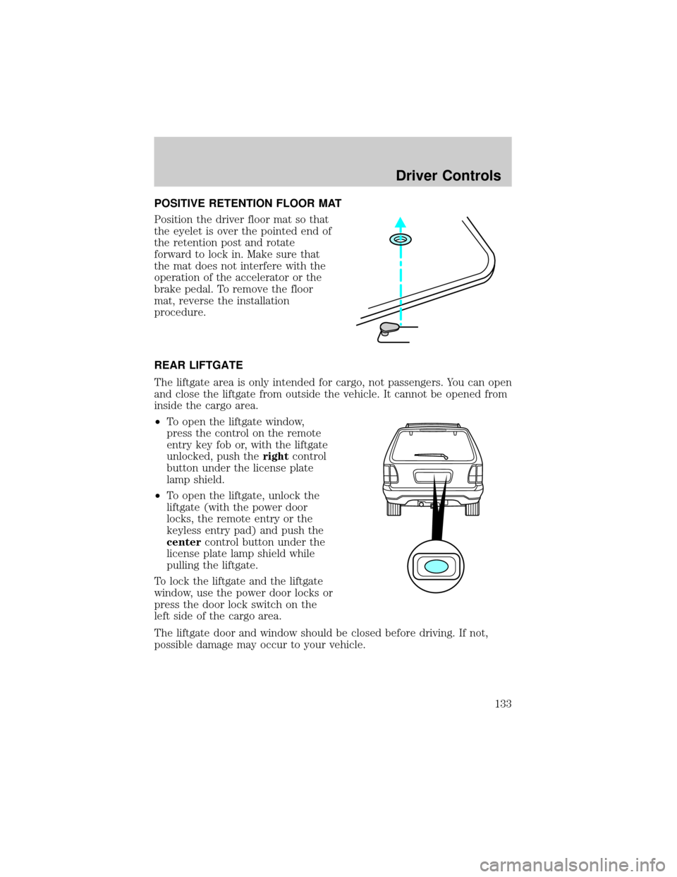
POSITIVE RETENTION FLOOR MAT
Position the driver floor mat so that
the eyelet is over the pointed end of
the retention post and rotate
forward to lock in. Make sure that
the mat does not interfere with the
operation of the accelerator or the
brake pedal. To remove the floor
mat, reverse the installation
procedure.
REAR LIFTGATE
The liftgate area is only intended for cargo, not passengers. You can open
and close the liftgate from outside the vehicle. It cannot be opened from
inside the cargo area.
²To open the liftgate window,
press the control on the remote
entry key fob or, with the liftgate
unlocked, push therightcontrol
button under the license plate
lamp shield.
²To open the liftgate, unlock the
liftgate (with the power door
locks, the remote entry or the
keyless entry pad) and push the
centercontrol button under the
license plate lamp shield while
pulling the liftgate.
To lock the liftgate and the liftgate
window, use the power door locks or
press the door lock switch on the
left side of the cargo area.
The liftgate door and window should be closed before driving. If not,
possible damage may occur to your vehicle.
Driver Controls
133
Page 134 of 336
Always close liftgate window before opening liftgate. Liftgate
glass and liftgate should never be open at the same time. Failure
to observe this warning may result in personal injury or damage to
your vehicle.
Make sure the liftgate door and/or window are closed to prevent
exhaust fumes from being drawn into the vehicle. This will also
prevent passengers and cargo from falling out.
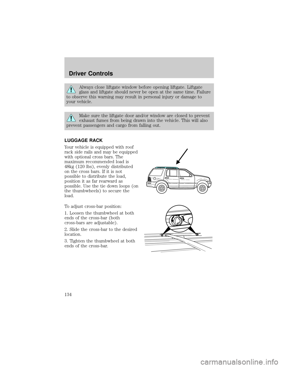
LUGGAGE RACK
Your vehicle is equipped with roof
rack side rails and may be equipped
with optional cross bars. The
maximum recommended load is
48kg (120 lbs), evenly distributed
on the cross bars. If it is not
possible to distribute the load,
position it as far rearward as
possible. Use the tie down loops (on
the thumbwheels) to secure the
load.
To adjust cross-bar position:
1. Loosen the thumbwheel at both
ends of the cross-bar (both
cross-bars are adjustable).
2. Slide the cross-bar to the desired
location.
3. Tighten the thumbwheel at both
ends of the cross-bar.
Driver Controls
134
Page 137 of 336
Deactivating/activating the autolock feature
The autolock feature may be deactivated/activated by selecting the
autolock function (accessed by pressing the SETUP control). Press the
RESET control to turn the autolock function ON or OFF. Refer to
Message centerin theDriver Controlschapter for additional
information.
The autolock feature may also be deactivated/activated using the keyless
entry keypad. For additional information, refer toKeyless entry system
in this chapter.
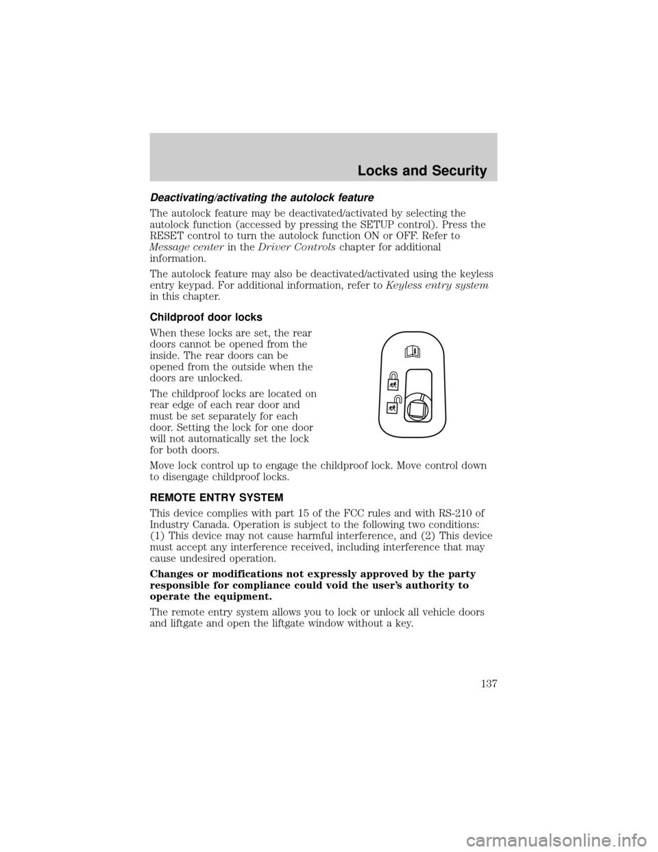
Childproof door locks
When these locks are set, the rear
doors cannot be opened from the
inside. The rear doors can be
opened from the outside when the
doors are unlocked.
The childproof locks are located on
rear edge of each rear door and
must be set separately for each
door. Setting the lock for one door
will not automatically set the lock
for both doors.
Move lock control up to engage the childproof lock. Move control down
to disengage childproof locks.
REMOTE ENTRY SYSTEM
This device complies with part 15 of the FCC rules and with RS-210 of
Industry Canada. Operation is subject to the following two conditions:
(1) This device may not cause harmful interference, and (2) This device
must accept any interference received, including interference that may
cause undesired operation.
Changes or modifications not expressly approved by the party
responsible for compliance could void the user's authority to
operate the equipment.
The remote entry system allows you to lock or unlock all vehicle doors
and liftgate and open the liftgate window without a key.
Locks and Security
137
Page 150 of 336
Arming the system
When armed, this system will help protect your vehicle from
unauthorized entry. When unauthorized entry occurs, the system will
flash the headlamps and/or parking lamps, and will chirp the horn.
The system is ready to arm whenever the key is removed from the
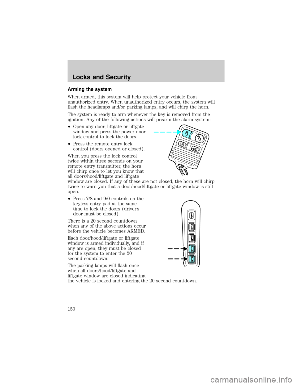
ignition. Any of the following actions will prearm the alarm system:
²Open any door, liftgate or liftgate
window and press the power door
lock control to lock the doors.
²Press the remote entry lock
control (doors opened or closed).
When you press the lock control
twice within three seconds on your
remote entry transmitter, the horn
will chirp once to let you know that
all doors/hood/liftgate and liftgate
window are closed. If any of these are not closed, the horn will chirp
twice to warn you that a door/hood/liftgate or liftgate window is still
open.
²Press 7/8 and 9/0 controls on the
keyless entry pad at the same
time to lock the doors (driver's
door must be closed).
There is a 20 second countdown
when any of the above actions occur
before the vehicle becomes ARMED.
Each door/hood/liftgate or liftgate
window is armed individually, and if
any are open, they must be closed
for the system to enter the 20
second countdown.
The parking lamps will flash once
when all doors/hood/liftgate and
liftgate window are closed indicating
the vehicle is locked and entering the 20 second countdown.
Locks and Security
150
Page 152 of 336
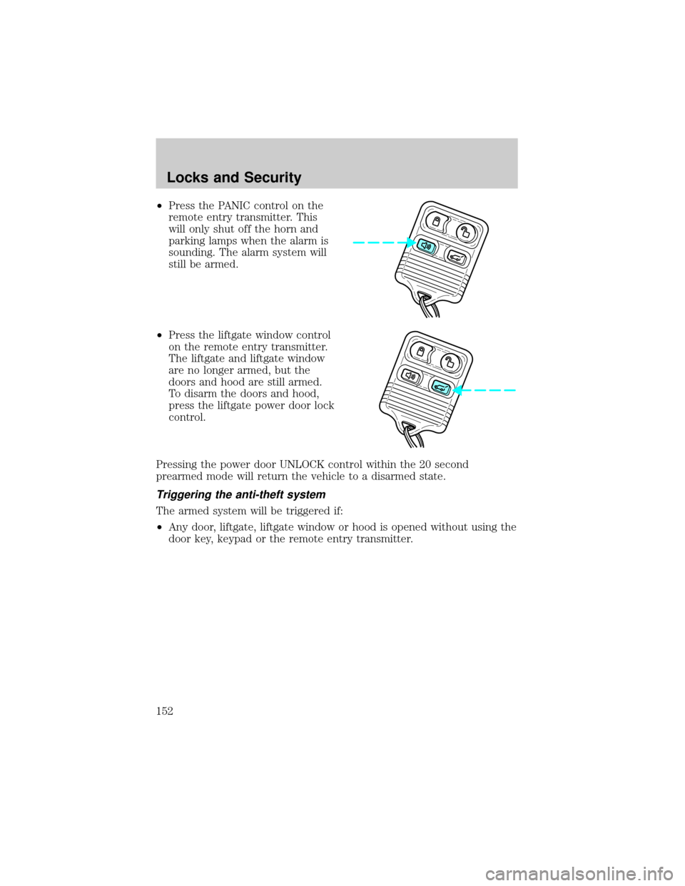
²Press the PANIC control on the
remote entry transmitter. This
will only shut off the horn and
parking lamps when the alarm is
sounding. The alarm system will
still be armed.
²Press the liftgate window control
on the remote entry transmitter.
The liftgate and liftgate window
are no longer armed, but the
doors and hood are still armed.
To disarm the doors and hood,
press the liftgate power door lock
control.
Pressing the power door UNLOCK control within the 20 second
prearmed mode will return the vehicle to a disarmed state.
Triggering the anti-theft system
The armed system will be triggered if:
²Any door, liftgate, liftgate window or hood is opened without using the
door key, keypad or the remote entry transmitter.
Locks and Security
152
Page 236 of 336
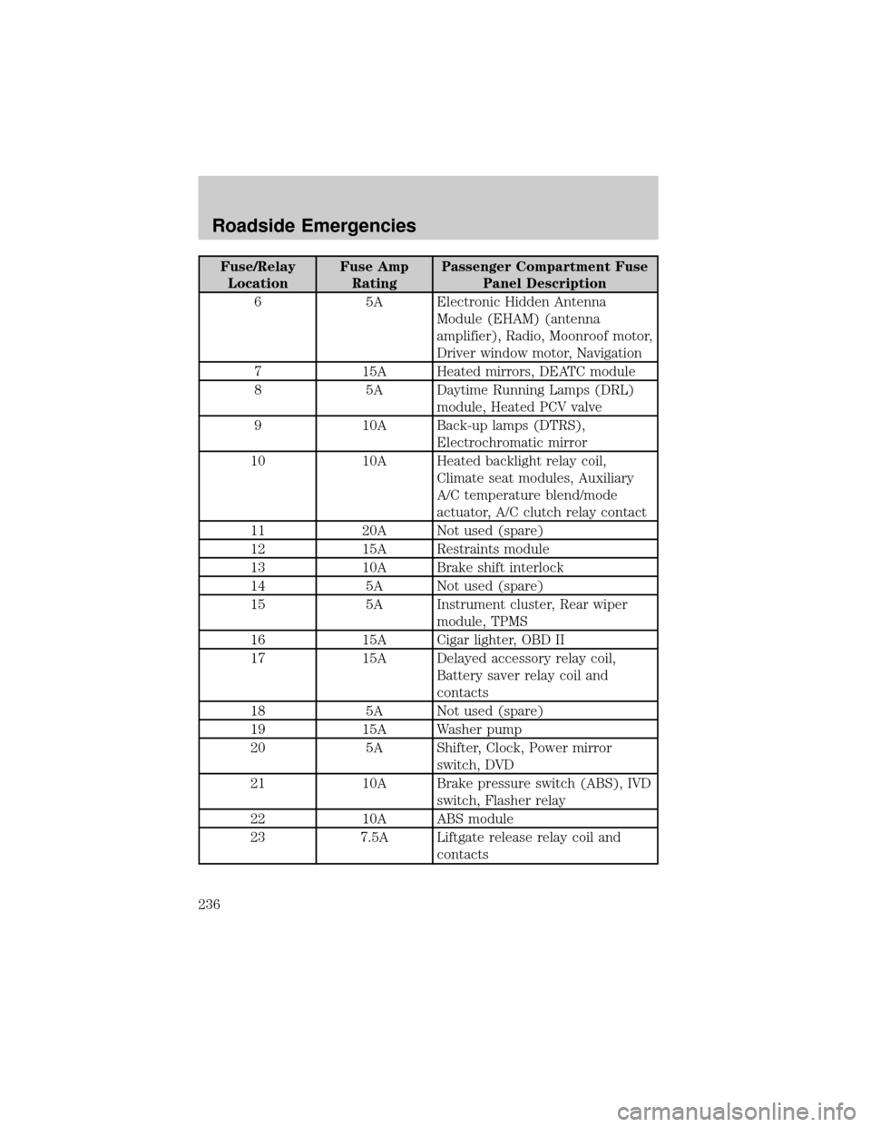
Fuse/Relay
LocationFuse Amp
RatingPassenger Compartment Fuse
Panel Description
6 5A Electronic Hidden Antenna
Module (EHAM) (antenna
amplifier), Radio, Moonroof motor,
Driver window motor, Navigation
7 15A Heated mirrors, DEATC module
8 5A Daytime Running Lamps (DRL)
module, Heated PCV valve
9 10A Back-up lamps (DTRS),
Electrochromatic mirror
10 10A Heated backlight relay coil,
Climate seat modules, Auxiliary
A/C temperature blend/mode
actuator, A/C clutch relay contact
11 20A Not used (spare)
12 15A Restraints module
13 10A Brake shift interlock
14 5A Not used (spare)
15 5A Instrument cluster, Rear wiper
module, TPMS
16 15A Cigar lighter, OBD II
17 15A Delayed accessory relay coil,
Battery saver relay coil and
contacts
18 5A Not used (spare)
19 15A Washer pump
20 5A Shifter, Clock, Power mirror
switch, DVD
21 10A Brake pressure switch (ABS), IVD
switch, Flasher relay
22 10A ABS module
23 7.5A Liftgate release relay coil and
contacts
Roadside Emergencies
236