headlamp LINCOLN AVIATOR 2023 Owner's Manual
[x] Cancel search | Manufacturer: LINCOLN, Model Year: 2023, Model line: AVIATOR, Model: LINCOLN AVIATOR 2023Pages: 681, PDF Size: 9.33 MB
Page 326 of 681
Note:The Alert and Aid diagrams illustrate
general zone coverage. They do not provide
exact zone parameters.
Intensity: This setting affects the intensity of
the steering wheel vibration used for the
Alert and Alert and Aid modes. This setting
does not affect the Aid mode.
• Low.
• Normal.
• High.System Display
E272890
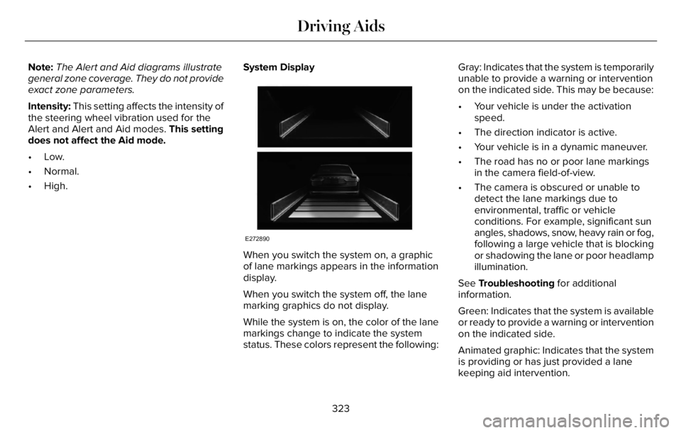
When you switch the system on, a graphic
of lane markings appears in the information
display.
When you switch the system off, the lane
marking graphics do not display.
While the system is on, the color of the lane
markings change to indicate the system
status. These colors represent the following:Gray: Indicates that the system is temporarily
unable to provide a warning or intervention
on the indicated side. This may be because:
• Your vehicle is under the activation
speed.
• The direction indicator is active.
• Your vehicle is in a dynamic maneuver.
• The road has no or poor lane markings
in the camera field-of-view.
• The camera is obscured or unable to
detect the lane markings due to
environmental, traffic or vehicle
conditions. For example, significant sun
angles, shadows, snow, heavy rain or fog,
following a large vehicle that is blocking
or shadowing the lane or poor headlamp
illumination.
See Troubleshooting for additional
information.
Green: Indicates that the system is available
or ready to provide a warning or intervention
on the indicated side.
Animated graphic: Indicates that the system
is providing or has just provided a lane
keeping aid intervention.
323
Driving Aids
Page 338 of 681
SPEED SIGN RECOGNITION (IF
EQUIPPED)
Principle of Operation
WARNING: You are responsible for
controlling your vehicle at all times. The
system is designed to be an aid and does
not relieve you of your responsibility to
drive with due care and attention. Failure
to follow this instruction could result in the
loss of control of your vehicle, personal
injury or death.
WARNING: In cold and severe
weather conditions the system may not
function. Rain, snow and spray can all limit
sensor performance.
WARNING: The system may not
operate properly if the sensor is blocked.
Keep the windshield free from obstruction.The system is designed to detect speed limit
signs to inform you of the current speed limit.
Detected speed signs appear in the
information display. The sensor is behind the
interior mirror.
Note:Do not carry out windshield repairs in
the immediate area surrounding the sensor.
Note:Speed sign data provided by the
navigation system contains information
integrated to the data carrier release.
Note:The system may not detect or correctly
read all speed signs.
Note:If your vehicle has a suspension kit
not approved by us, the system may not
correctly function.
Note:Always replace headlamp bulbs with
those specifically designed for your vehicle.
Other bulbs could reduce system
performance.
The system turns on when you switch the
ignition on, and you cannot switch the system
off.
Using Speed Sign Recognition
Setting the System Speed Warning
You can set the system speed warning to
alert you when the vehicle speed exceeds
the speed limit recognized by the system by
a certain speed tolerance.
Note:The system remembers the last setting
when you start your vehicle.
System Display
E317824E317824
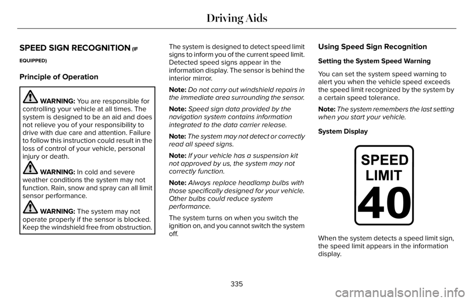
When the system detects a speed limit sign,
the speed limit appears in the information
display.
335
Driving Aids
Page 388 of 681
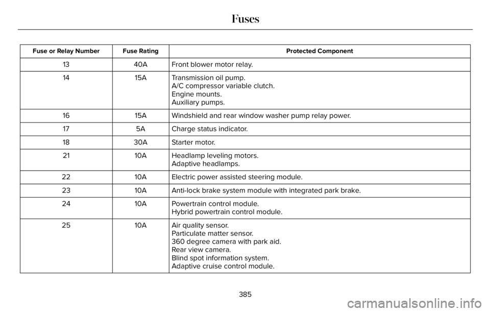
Protected Component Fuse Rating Fuse or Relay Number
Front blower motor relay. 40A 13
Transmission oil pump. 15A 14
A/C compressor variable clutch.
Engine mounts.
Auxiliary pumps.
Windshield and rear window washer pump relay power. 15A 16
Charge status indicator. 5A 17
Starter motor. 30A 18
Headlamp leveling motors. 10A 21
Adaptive headlamps.
Electric power assisted steering module. 10A 22
Anti-lock brake system module with integrated park brake. 10A 23
Powertrain control module. 10A 24
Hybrid powertrain control module.
Air quality sensor. 10A 25
Particulate matter sensor.
360 degree camera with park aid.
Rear view camera.
Blind spot information system.
Adaptive cruise control module.
385
Fuses
Page 390 of 681
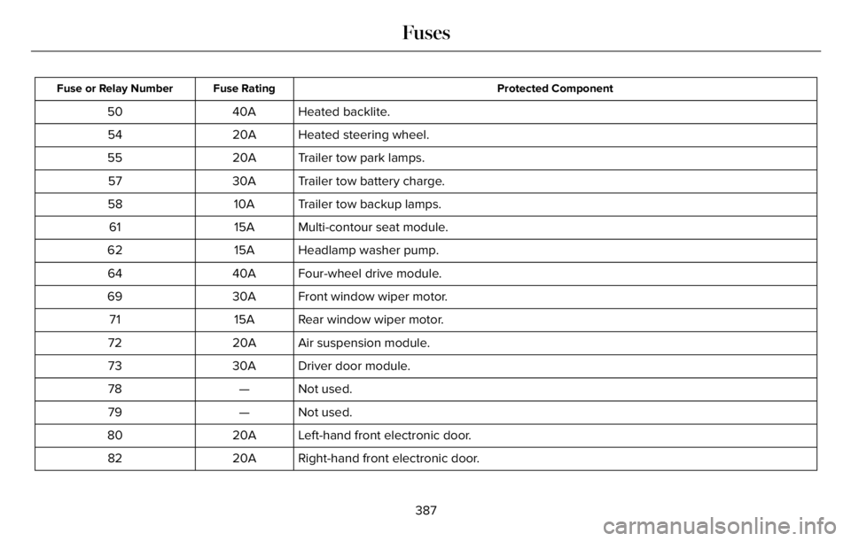
Protected Component Fuse Rating Fuse or Relay Number
Heated backlite. 40A 50
Heated steering wheel. 20A 54
Trailer tow park lamps. 20A 55
Trailer tow battery charge. 30A 57
Trailer tow backup lamps. 10A 58
Multi-contour seat module. 15A 61
Headlamp washer pump. 15A 62
Four-wheel drive module. 40A 64
Front window wiper motor. 30A 69
Rear window wiper motor. 15A 71
Air suspension module. 20A 72
Driver door module. 30A 73
Not used. — 78
Not used. — 79
Left-hand front electronic door. 20A 80
Right-hand front electronic door. 20A 82
387
Fuses
Page 393 of 681
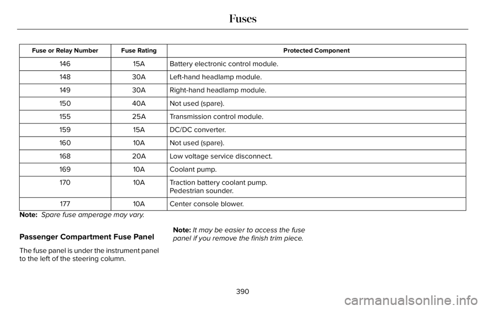
Protected Component Fuse Rating Fuse or Relay Number
Battery electronic control module. 15A 146
Left-hand headlamp module. 30A 148
Right-hand headlamp module. 30A 149
Not used (spare). 40A 150
Transmission control module. 25A 155
DC/DC converter. 15A 159
Not used (spare). 10A 160
Low voltage service disconnect. 20A 168
Coolant pump. 10A 169
Traction battery coolant pump. 10A 170
Pedestrian sounder.
Center console blower. 10A 177
Note: Spare fuse amperage may vary.
Passenger Compartment Fuse Panel
The fuse panel is under the instrument panel
to the left of the steering column.Note:It may be easier to access the fuse
panel if you remove the finish trim piece.
390
Fuses
Page 396 of 681
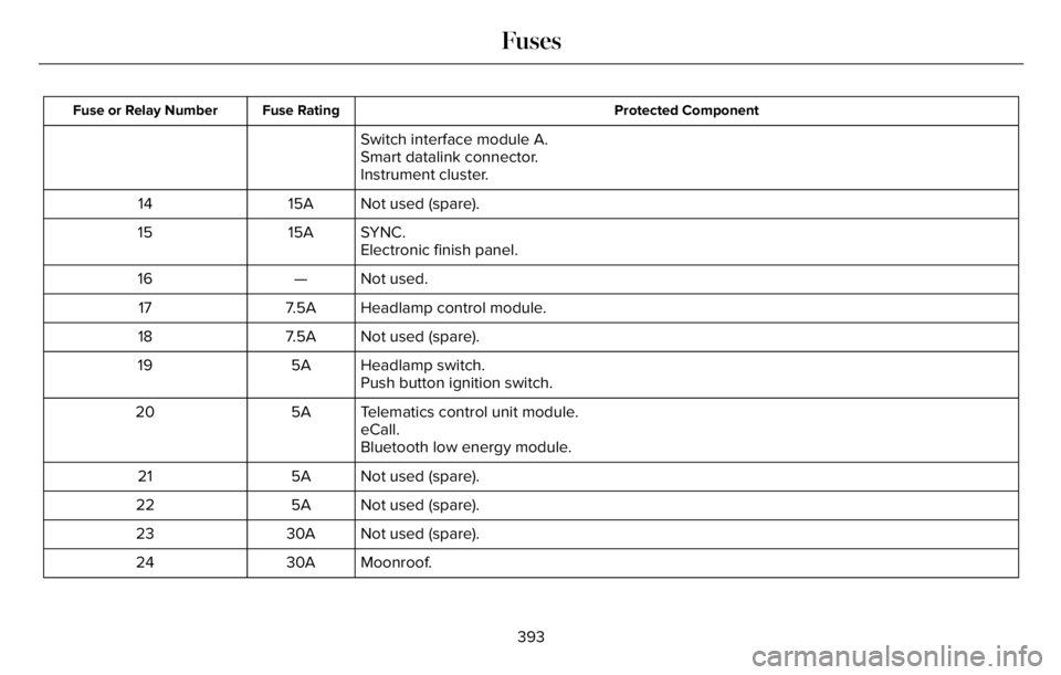
Protected Component Fuse Rating Fuse or Relay Number
Switch interface module A.
Smart datalink connector.
Instrument cluster.
Not used (spare). 15A 14
SYNC. 15A 15
Electronic finish panel.
Not used. — 16
Headlamp control module. 7.5A 17
Not used (spare). 7.5A 18
Headlamp switch. 5A 19
Push button ignition switch.
Telematics control unit module. 5A 20
eCall.
Bluetooth low energy module.
Not used (spare). 5A 21
Not used (spare). 5A 22
Not used (spare). 30A 23
Moonroof. 30A 24
393
Fuses
Page 414 of 681
For longer, trouble-free operation, keep the
top of the battery clean and dry and the
battery cables tightly fastened to the battery
terminals. If any corrosion is present on the
battery or terminals, remove the cables from
the terminals and clean with a wire brush.
You can neutralize the acid with a solution
of baking soda and water.
We recommend that you disconnect the
negative battery cable terminal from the
battery if you plan to store your vehicle for
an extended period.
Note:If you only disconnect the negative
battery cable terminal, make sure it is
isolated or placed away from the battery
terminal to avoid unintended connection or
arcing.
If you replace the battery make sure it
matches the electrical requirements of your
vehicle.If you disconnect or replace the battery and
your vehicle has an automatic transmission,
it must relearn its adaptive strategy. Because
of this, the transmission may shift firmly when
first driven. This is normal operation while
the transmission fully updates its operation
to optimum shift feel.
Battery Sensor Reset
When you install a new battery, reset the
battery sensor by doing the following:
1. Switch the ignition on, and leave the
engine off.
Note:Complete Steps 2 and 3 within 10
seconds.
2. Flash the high beam headlamps five
times, ending with the high beams off.
3. Press and release the brake pedal three
times.
The battery warning lamp flashes three times
to confirm that the reset is successful.
Battery Management System (If Equipped)
The system monitors battery conditions and
takes actions to extend battery life. If
excessive battery drain is detected, the
system temporarily disables some electrical
systems to protect the battery.
Systems included are:
• Heated rear window.
• Heated seats.
• Climate control.
• Heated steering wheel.
• Audio unit.
• Navigation system.
A message may appear in the information
display to alert you that battery protection
actions are active. This message is only for
notification that an action is taking place, and
not intended to indicate an electrical problem
or that the battery requires replacement.
411
Maintenance
Page 417 of 681
39E371794
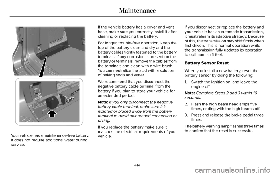
Your vehicle has a maintenance-free battery.
It does not require additional water during
service.If the vehicle battery has a cover and vent
hose, make sure you correctly install it after
cleaning or replacing the battery.
For longer, trouble-free operation, keep the
top of the battery clean and dry and the
battery cables tightly fastened to the battery
terminals. If any corrosion is present on the
battery or terminals, remove the cables from
the terminals and clean with a wire brush.
You can neutralize the acid with a solution
of baking soda and water.
We recommend that you disconnect the
negative battery cable terminal from the
battery if you plan to store your vehicle for
an extended period.
Note:If you only disconnect the negative
battery cable terminal, make sure it is
isolated or placed away from the battery
terminal to avoid unintended connection or
arcing.
If you replace the battery make sure it
matches the electrical requirements of your
vehicle.If you disconnect or replace the battery and
your vehicle has an automatic transmission,
it must relearn its adaptive strategy. Because
of this, the transmission may shift firmly when
first driven. This is normal operation while
the transmission fully updates its operation
to optimum shift feel.
Battery Sensor Reset
When you install a new battery, reset the
battery sensor by doing the following:
1. Switch the ignition on, and leave the
engine off.
Note:Complete Steps 2 and 3 within 10
seconds.
2. Flash the high beam headlamps five
times, ending with the high beams off.
3. Press and release the brake pedal three
times.
The battery warning lamp flashes three times
to confirm that the reset is successful.
414
Maintenance
Page 419 of 681
6. Remove the battery securing clamp.
7. Remove the battery.
8. To install, reverse the removal procedure.
Note:Before reconnecting the battery, make
sure the ignition remains switched off.
Note:Make sure to fully tighten the battery
cables.
If you disconnect or replace the vehicle
battery, you must reset the following
features:
• Window bounce-back. See Power
Windows (page 121).
• Clock Settings.
• Pre-set radio stations.
Battery Disposal
E107998
Make sure that you dispose of old
batteries in an environmentally
friendly way. Seek advice from
your local authority about recycling old
batteries.
ADJUSTING THE HEADLAMPS
Vertical Aim Adjustment
If your vehicle has been involved in a crash,
have the aim of the headlamp beam checked
by an authorized dealer.
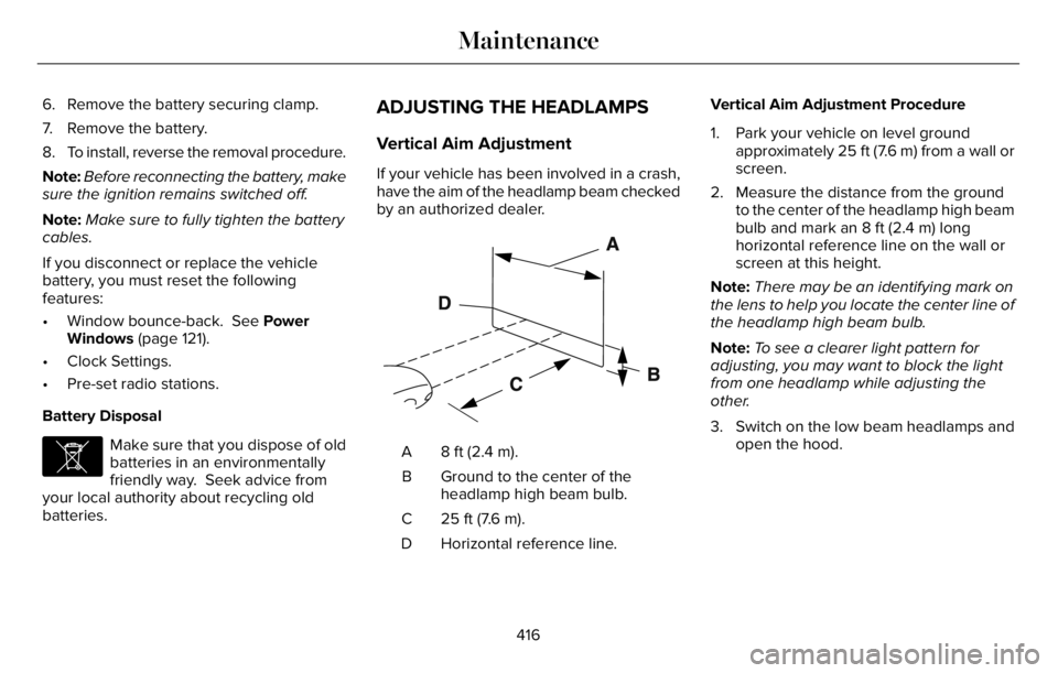
E142592
8 ft (2.4 m). A
Ground to the center of the
headlamp high beam bulb. B
25 ft (7.6 m). C
Horizontal reference line. DVertical Aim Adjustment Procedure
1. Park your vehicle on level ground
approximately 25 ft (7.6 m) from a wall or
screen.
2. Measure the distance from the ground
to the center of the headlamp high beam
bulb and mark an 8 ft (2.4 m) long
horizontal reference line on the wall or
screen at this height.
Note:There may be an identifying mark on
the lens to help you locate the center line of
the headlamp high beam bulb.
Note:To see a clearer light pattern for
adjusting, you may want to block the light
from one headlamp while adjusting the
other.
3. Switch on the low beam headlamps and
open the hood.
416
Maintenance
Page 420 of 681
E142465
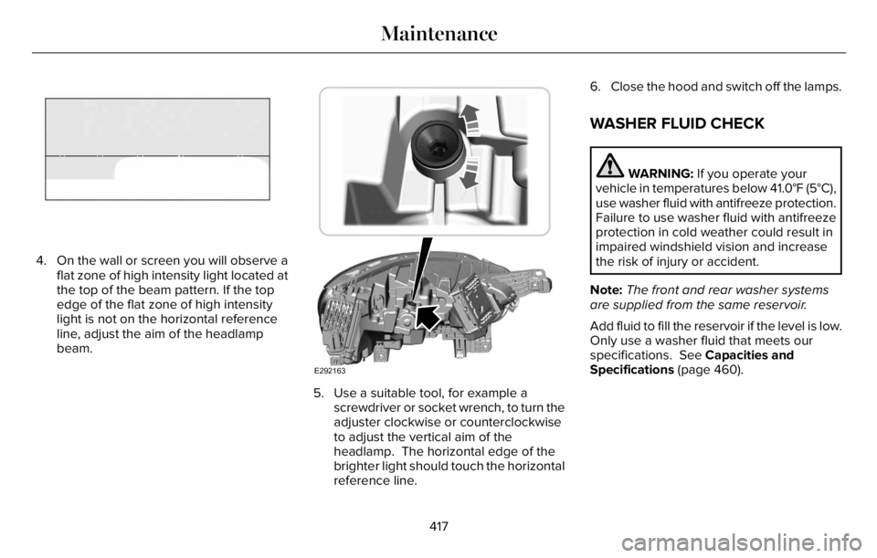
4. On the wall or screen you will observe a
flat zone of high intensity light located at
the top of the beam pattern. If the top
edge of the flat zone of high intensity
light is not on the horizontal reference
line, adjust the aim of the headlamp
beam.
E292163
5. Use a suitable tool, for example a
screwdriver or socket wrench, to turn the
adjuster clockwise or counterclockwise
to adjust the vertical aim of the
headlamp. The horizontal edge of the
brighter light should touch the horizontal
reference line.6. Close the hood and switch off the lamps.
WASHER FLUID CHECK
WARNING: If you operate your
vehicle in temperatures below 41.0°F (5°C),
use washer fluid with antifreeze protection.
Failure to use washer fluid with antifreeze
protection in cold weather could result in
impaired windshield vision and increase
the risk of injury or accident.
Note:The front and rear washer systems
are supplied from the same reservoir.
Add fluid to fill the reservoir if the level is low.
Only use a washer fluid that meets our
specifications. See Capacities and
Specifications (page 460).
417
Maintenance