fuel LINCOLN BLACKWOOD 2002 User Guide
[x] Cancel search | Manufacturer: LINCOLN, Model Year: 2002, Model line: BLACKWOOD, Model: LINCOLN BLACKWOOD 2002Pages: 248, PDF Size: 2.33 MB
Page 134 of 248
Wheel-speed sensors allow excess rear wheel spin to be detected by the
Traction Controlyportion of the ABS computer. Excess wheel spin is
controlled through engine torque reduction. This is realized via the fully
electronic spark and fuel injection systems. This process is very sensitive
to driving conditions and very fast acting. The rear wheels ªsearchº for
optimum traction several times a second and adjustments are made
accordingly.
The Traction Controlysystem will allow your vehicle to make better use
of available traction on slippery surfaces. The system is a driver aid
which makes your vehicle easier to handle primarily on snow and ice
covered roads.
During Traction Controlyoperation the engine will not ªrev-upº when
you push further on the accelerator. This is normal system behavior.
If you should become stuck in deep
snow or on a very slippery road
surface, try switching the Traction
Controlysystem off. This may allow
excess wheel spin to ªdigº the
vehicle out or enable a successful
ªrockingº maneuver.
TRACTION-LOK AXLE
This axle provides added traction on slippery surfaces, particularly when
one wheel is on a poor traction surface. Under normal conditions, the
Traction-Lok axle functions like a standard rear axle.
If a single drive wheel should spin-up, the Traction-Lok axle will transfer
torque to the other wheel if it has traction.
Extended use of other than the manufacturer's specified size tires on a
Traction-Lok rear axle could result in a permanent reduction in
effectiveness. This loss of effectiveness does not affect normal driving
and should not be noticeable to the driver.
To avoid injury, never run the engine with one wheel off the
ground, such as when changing a tire.
OFF
Driving
134
Page 138 of 248
(Overdrive)
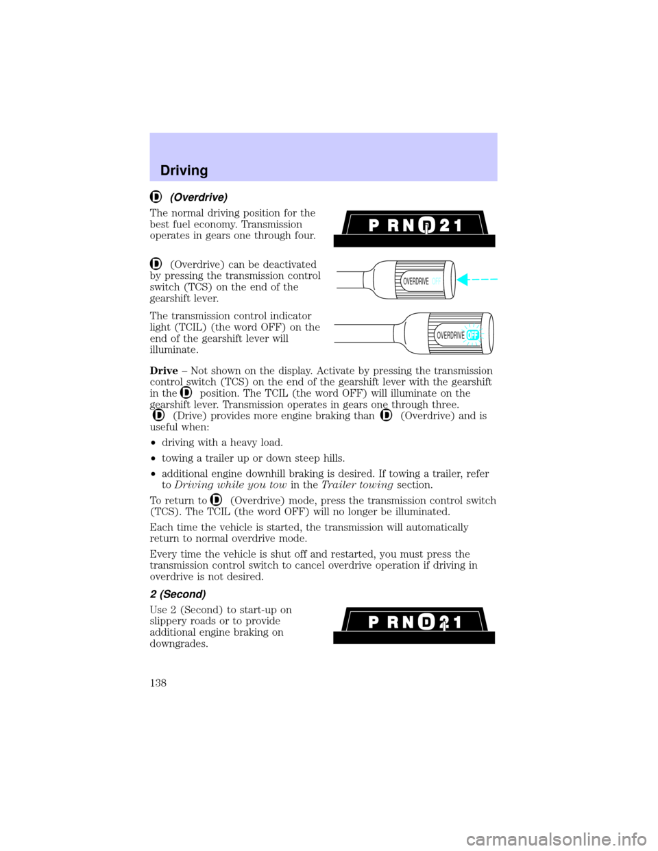
The normal driving position for the
best fuel economy. Transmission
operates in gears one through four.
(Overdrive) can be deactivated
by pressing the transmission control
switch (TCS) on the end of the
gearshift lever.
The transmission control indicator
light (TCIL) (the word OFF) on the
end of the gearshift lever will
illuminate.
Drive± Not shown on the display. Activate by pressing the transmission
control switch (TCS) on the end of the gearshift lever with the gearshift
in the
position. The TCIL (the word OFF) will illuminate on the
gearshift lever. Transmission operates in gears one through three.
(Drive) provides more engine braking than(Overdrive) and is
useful when:
²driving with a heavy load.
²towing a trailer up or down steep hills.
²additional engine downhill braking is desired. If towing a trailer, refer
toDriving while you towin theTrailer towingsection.
To return to
(Overdrive) mode, press the transmission control switch
(TCS). The TCIL (the word OFF) will no longer be illuminated.
Each time the vehicle is started, the transmission will automatically
return to normal overdrive mode.
Every time the vehicle is shut off and restarted, you must press the
transmission control switch to cancel overdrive operation if driving in
overdrive is not desired.
2 (Second)
Use 2 (Second) to start-up on
slippery roads or to provide
additional engine braking on
downgrades.
OVERDRIVEOFF
OVERDRIVE
Driving
138
Page 144 of 248
Do not connect a trailer's hydraulic brake system directly to your
vehicle's brake system. Your vehicle may not have enough
braking power and your chances of having a collision greatly increase.
The braking system of the tow vehicle is rated for operation at the
GVWR not GCWR.
Trailer lamps
Trailer lamps are required on most towed vehicles. Make sure your
trailer lamps conform to local and Federal regulations. See your dealer or
trailer rental agency for proper instructions and equipment for hooking
up trailer lamps.
Driving while you tow
When towing a trailer:
²Ensure that you turn off your speed control. The speed control may
shut off automatically when you are towing on long, steep grades.
²Consult your local motor vehicle speed regulations for towing a trailer.
²Use a lower gear when towing up or down steep hills. This will
eliminate excessive downshifting and upshifting for optimum fuel
economy and transmission cooling.
²Anticipate stops and brake gradually.
Exceeding the GCWR rating may cause internal transmission
damage and void your warranty coverage.
Servicing after towing
If you tow a trailer for long distances, your vehicle will require more
frequent service intervals. Refer to your scheduled maintenance guide for
more information.
Trailer towing tips
²Practice turning, stopping and backing up in an area before starting on
a trip to get the feel of the vehicle trailer combination. When turning,
make wider turns so the trailer wheels will clear curbs and other
obstacles.
²Allow more distance for stopping with a trailer attached.
²The trailer tongue weight should be 10% of the loaded trailer weight.
Driving
144
Page 147 of 248

GETTING ROADSIDE ASSISTANCE
To fully assist if you should have a vehicle concern, Ford offers a
complimentary roadside assistance program. This program is separate
from the New Vehicle Limited Warranty. The service is available:
²24±hours, seven days a week
²for the Basic warranty period (Canada) or New Vehicle Limited
Warranty period (U.S.) of three years or 60 000 km (36 000 miles),
whichever comes first on Ford and Mercury vehicles, and four years or
80 000 km (50 000 miles) on Lincoln vehicles
Roadside assistance will cover:
²changing a flat tire
²jump-starts
²lock-out assistance
²limited fuel delivery*
²towing of your disabled vehicle to the nearest Ford dealership, or your
selling dealer if within 25 kms (15.5 miles) of the nearest Ford
Dealership (one tow per disablement). Even non-warranty related
tows, like accidents or getting stuck in the mud or snow, are covered
(some exclusions apply, such as impound towing or repossession).
* Canadian customers refer to yourRoadside Assistance supplement
for exact fuel amounts.
Using roadside assistance
Complete the roadside assistance identification card and place it in your
wallet for quick reference. In the United States, this card is found in the
Owner Guide portfolio in the glove compartment in Ford vehicles and is
mailed to you if you own a Mercury or Lincoln. In Canada, the card is
found in the Roadside Assistance book in the glove compartment.
U.S. Ford or Mercury vehicle customers who require roadside assistance,
call 1±800±241±3673; Lincoln vehicle customers call 1±800±521±4140.
Canadian customers who require roadside assistance, call
1±800±665±2006.
Roadside emergencies
147
Page 148 of 248
If you need to arrange roadside assistance for yourself, Ford will
reimburse a reasonable amount. To obtain reimbursement information,
U.S. Ford or Mercury vehicles customers call 1-800-241-3673; Lincoln
vehicle customers call 1±800±521±4140.
Canadian customers who need to obtain reimbursement information, call
1±800±665±2006.
Roadside coverage beyond basic warranty
In the United States, you may purchase additional roadside assistance
coverage beyond this period through the Ford Auto Club by contacting
your Ford or Lincoln Mercury dealer.
Similarly in Canada, for uninterrupted Roadside Assistance coverage, you
may purchase extended coverage prior to your Basic Warranty's Roadside
Assistance expiring. For more information and enrollment, contact
1±877±294±2582 or visit our website at www.ford.ca.
HAZARD FLASHER
Use only in an emergency to warn traffic of vehicle breakdown,
approaching danger, etc. The hazard flashers can be operated when the
ignition is off.
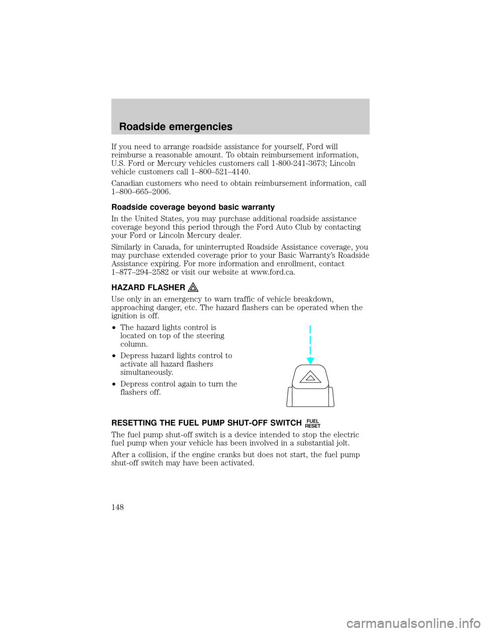
²The hazard lights control is
located on top of the steering
column.
²Depress hazard lights control to
activate all hazard flashers
simultaneously.
²Depress control again to turn the
flashers off.
RESETTING THE FUEL PUMP SHUT-OFF SWITCH
FUEL
RESET
The fuel pump shut-off switch is a device intended to stop the electric
fuel pump when your vehicle has been involved in a substantial jolt.
After a collision, if the engine cranks but does not start, the fuel pump
shut-off switch may have been activated.
Roadside emergencies
148
Page 149 of 248
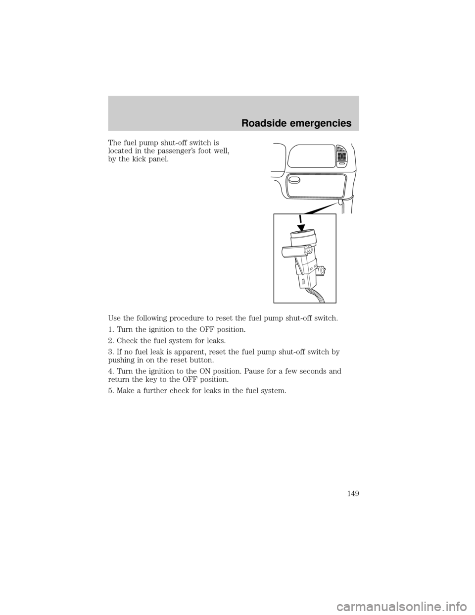
The fuel pump shut-off switch is
located in the passenger's foot well,
by the kick panel.
Use the following procedure to reset the fuel pump shut-off switch.
1. Turn the ignition to the OFF position.
2. Check the fuel system for leaks.
3. If no fuel leak is apparent, reset the fuel pump shut-off switch by
pushing in on the reset button.
4. Turn the ignition to the ON position. Pause for a few seconds and
return the key to the OFF position.
5. Make a further check for leaks in the fuel system.
Roadside emergencies
149
Page 154 of 248
Always replace the cover to the Power Distribution Box before
reconnecting the battery or refilling fluid reservoirs.
If the battery has been disconnected and reconnected, refer to the
Batterysection of theMaintenance and specificationschapter.
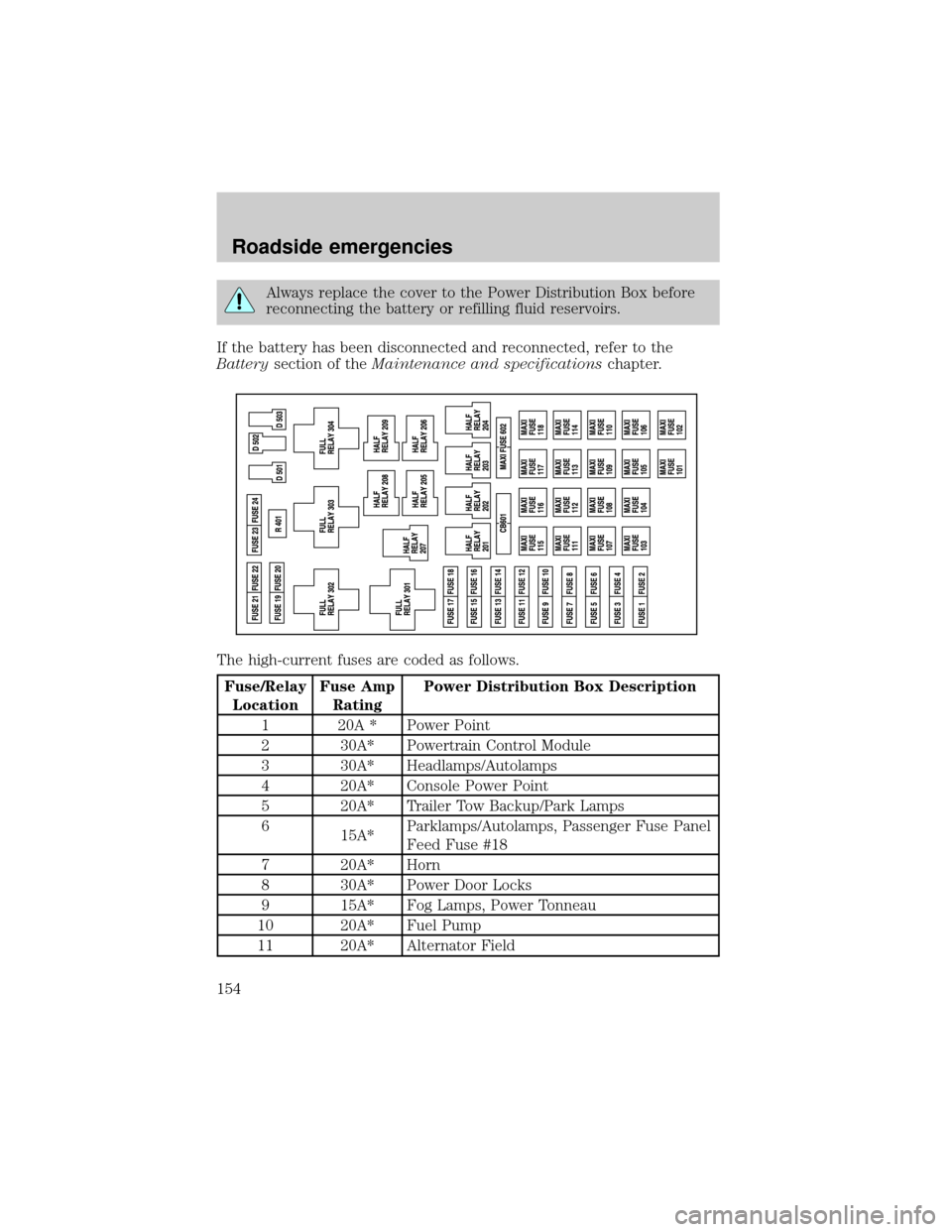
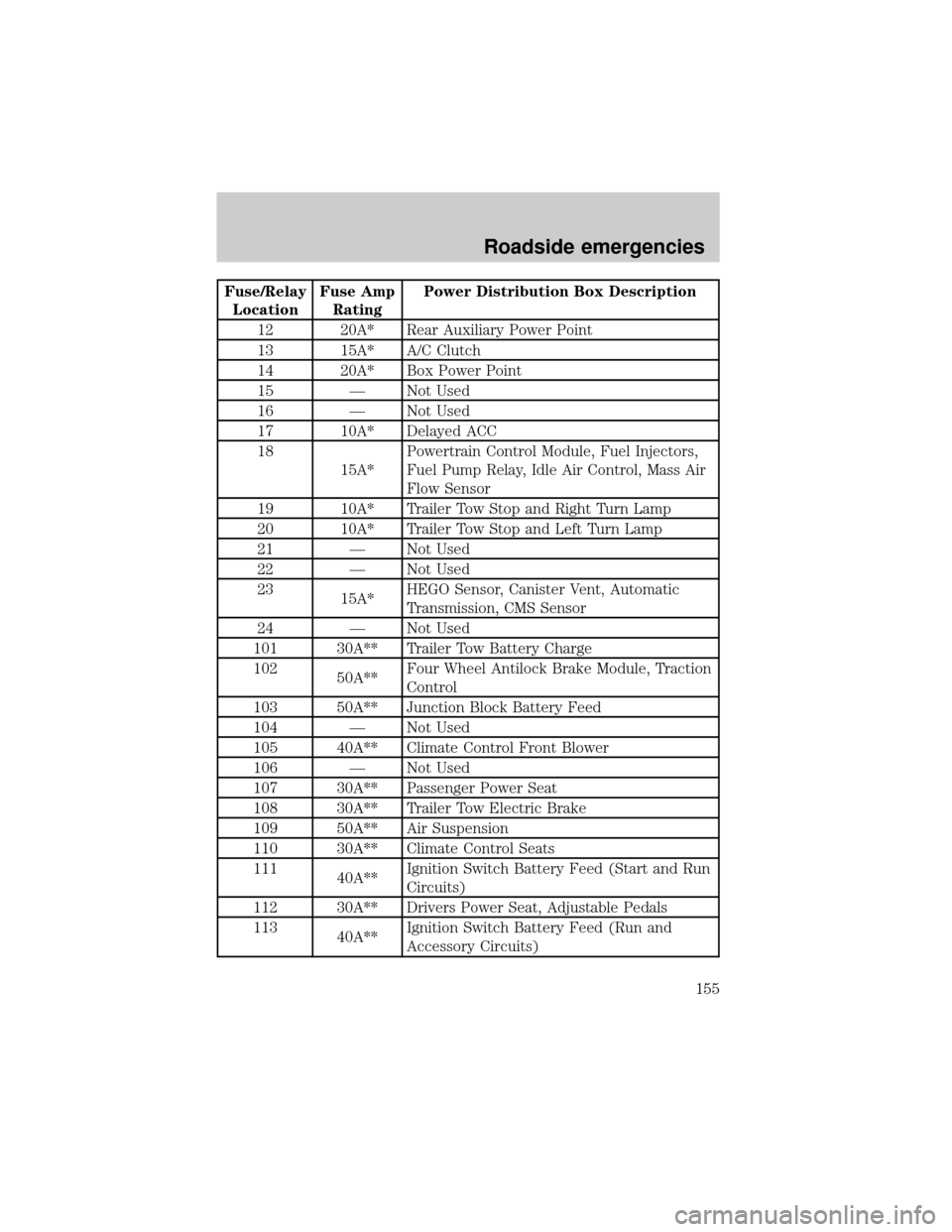
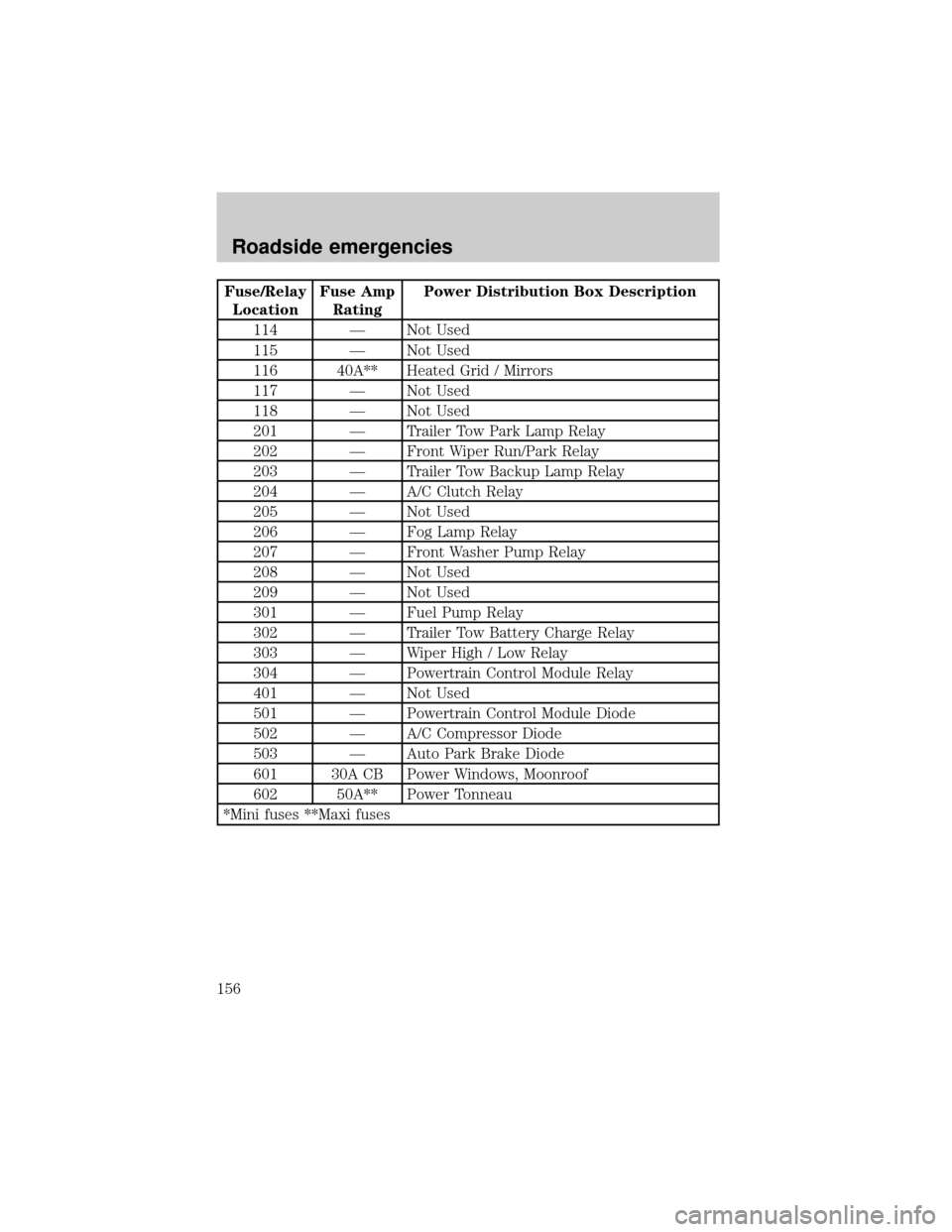
The high-current fuses are coded as follows.
Fuse/Relay
LocationFuse Amp
RatingPower Distribution Box Description
1 20A * Power Point
2 30A* Powertrain Control Module
3 30A* Headlamps/Autolamps
4 20A* Console Power Point
5 20A* Trailer Tow Backup/Park Lamps
6
15A*Parklamps/Autolamps, Passenger Fuse Panel
Feed Fuse #18
7 20A* Horn
8 30A* Power Door Locks
9 15A* Fog Lamps, Power Tonneau
10 20A* Fuel Pump
11 20A* Alternator Field
Roadside emergencies
154
Page 155 of 248
Fuse/Relay
LocationFuse Amp
RatingPower Distribution Box Description
12 20A* Rear Auxiliary Power Point
13 15A* A/C Clutch
14 20A* Box Power Point
15 Ð Not Used
16 Ð Not Used
17 10A* Delayed ACC
18
15A*Powertrain Control Module, Fuel Injectors,
Fuel Pump Relay, Idle Air Control, Mass Air
Flow Sensor
19 10A* Trailer Tow Stop and Right Turn Lamp
20 10A* Trailer Tow Stop and Left Turn Lamp
21 Ð Not Used
22 Ð Not Used
23
15A*HEGO Sensor, Canister Vent, Automatic
Transmission, CMS Sensor
24 Ð Not Used
101 30A** Trailer Tow Battery Charge
102
50A**Four Wheel Antilock Brake Module, Traction
Control
103 50A** Junction Block Battery Feed
104 Ð Not Used
105 40A** Climate Control Front Blower
106 Ð Not Used
107 30A** Passenger Power Seat
108 30A** Trailer Tow Electric Brake
109 50A** Air Suspension
110 30A** Climate Control Seats
111
40A**Ignition Switch Battery Feed (Start and Run
Circuits)
112 30A** Drivers Power Seat, Adjustable Pedals
113
40A**Ignition Switch Battery Feed (Run and
Accessory Circuits)
Roadside emergencies
155
Page 156 of 248
Fuse/Relay
LocationFuse Amp
RatingPower Distribution Box Description
114 Ð Not Used
115 Ð Not Used
116 40A** Heated Grid / Mirrors
117 Ð Not Used
118 Ð Not Used
201 Ð Trailer Tow Park Lamp Relay
202 Ð Front Wiper Run/Park Relay
203 Ð Trailer Tow Backup Lamp Relay
204 Ð A/C Clutch Relay
205 Ð Not Used
206 Ð Fog Lamp Relay
207 Ð Front Washer Pump Relay
208 Ð Not Used
209 Ð Not Used
301 Ð Fuel Pump Relay
302 Ð Trailer Tow Battery Charge Relay
303 Ð Wiper High / Low Relay
304 Ð Powertrain Control Module Relay
401 Ð Not Used
501 Ð Powertrain Control Module Diode
502 Ð A/C Compressor Diode
503 Ð Auto Park Brake Diode
601 30A CB Power Windows, Moonroof
602 50A** Power Tonneau
*Mini fuses **Maxi fuses
Roadside emergencies
156
Page 164 of 248
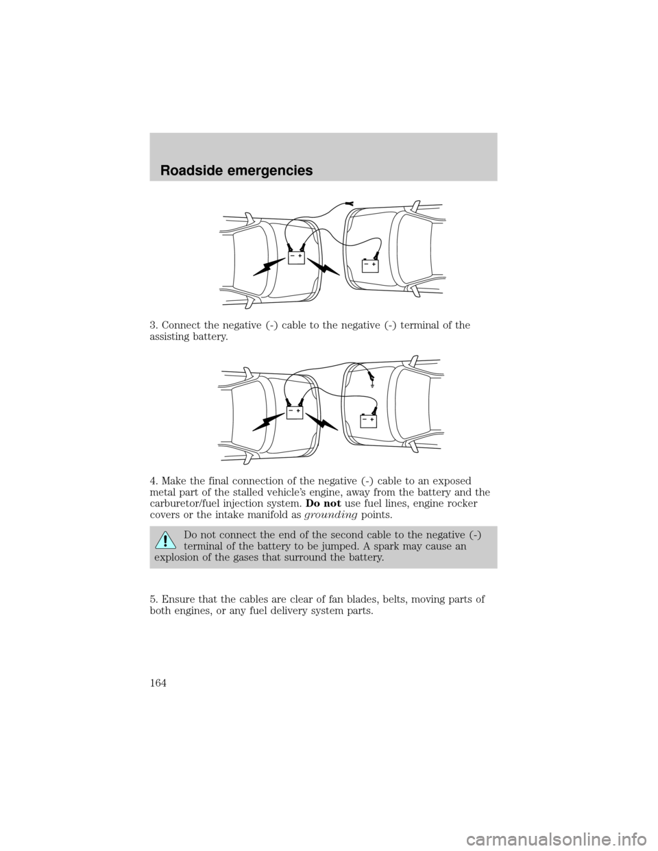
3. Connect the negative (-) cable to the negative (-) terminal of the
assisting battery.
4. Make the final connection of the negative (-) cable to an exposed
metal part of the stalled vehicle's engine, away from the battery and the
carburetor/fuel injection system.Do notuse fuel lines, engine rocker
covers or the intake manifold asgroundingpoints.
Do not connect the end of the second cable to the negative (-)
terminal of the battery to be jumped. A spark may cause an
explosion of the gases that surround the battery.
5. Ensure that the cables are clear of fan blades, belts, moving parts of
both engines, or any fuel delivery system parts.
+–+–
+–+–
Roadside emergencies
164