LINCOLN MARK VIII 1998 Owners Manual
Manufacturer: LINCOLN, Model Year: 1998, Model line: MARK VIII, Model: LINCOLN MARK VIII 1998Pages: 170, PDF Size: 1.37 MB
Page 111 of 170

Fuse/Relay
LocationFuse Amp
RatingDescription
25 10A Steering Column/Ignition/Lighting Module
(Right Low-Beam Headlamp)
26 15A Steering Column/Ignition/Lighting Module
(Courtesy Lighting, Demand Lighting)
27 Ð Not Used
28 10A Instrument Cluster, I/P Warning Indicator
Display, Air Suspension/EVO Steering
Module, Rear Window Defrost Module,
Steering Wheel Position Sensor,
Transmission Control Switch
29 Ð Not Used
30 10A Heated Mirrors
31 10A Steering Column/Ignition/Lighting Module
(Park Lamps)
32 15A Brake On/Off Switch, Brake Pressure
Switch
33 Ð Not Used
34 15A Heated Seats, Backup Lamps, Speed
Control, Daytime Running Lamps, A/C
Cycling Switch, Digital Transmission Range
Sensor, Intake Manifold Runner Control
Module
35 10A Driver's Power and Heated Seats
36 Ð Not Used
37 Ð Not Used
38 10A Data Link Connector
39 Ð Not Used
40 Ð Not Used
41 10A Keyless Entry, Power Door Locks, Power
Mirror Switch, Memory/Recall Switch,
Driver's Door Module
Roadside emergencies
112
Page 112 of 170
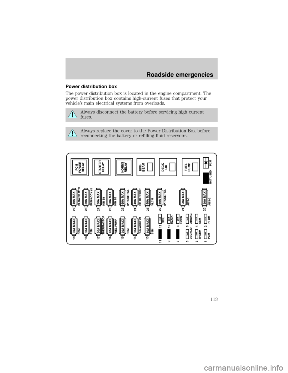
Power distribution box
The power distribution box is located in the engine compartment. The
power distribution box contains high-current fuses that protect your
vehicle's main electrical systems from overloads.
Always disconnect the battery before servicing high current
fuses.
Always replace the cover to the Power Distribution Box before
reconnecting the battery or refilling fluid reservoirs.
30A MAXI 20A MAXI 40A MAXI
PCM
POWER
RELAY
STARTER
RELAY
HORNS
RELAY
HIGH
BEAM
FUEL
PUMPDECK
LID 30A MAXI
30A MAXI
30A MAXI
30A MAXI
30A MAXI
20A MAXI
20A MAXI
60A MAXI
30A MAXI
40A MAXI
30A MAXI
40A MAXI
60A MAXI 60A MAXI
15A 15A 10A
10A 10A 30A20A 20A 15A
PCM
PCM HI BM
NOT USED SCIL
RADIO
HORN
AIRBAG DECKLID
SSM THERMDSM
PSM
THERMACTOR
FUEL PUMP
PCM
RUN/ACCY #1
SSMBLOWER MTR
RUN/ACCY #2
IGN B1
IGN B2
IP FUSE PNL
RR DEFROST
VLCM
IP FUSE PNL
ABS-3
ABS-21122 23 24 25 26 27 28 29 19
18
17
16
15
14
13
21
20 9
7
5
3
112
10
8
6
4
2
Roadside emergencies
113
Page 113 of 170

The high-current fuses are coded as follows.
Fuse/Relay
LocationFuse Amp
RatingDescription
1 10A* Powertrain Control Module (Keep-Alive
Memory)
2 15A* High Beam Relay, Daytime Running Lamps
Module
3 10A* Powertrain Control Module (EAM Pump
Motor-Monitor)
4 15A* Air Suspension, Electronically Variable
Orifice Power Steering
5 30A* Trunk Lid Relay, Fuel Filler Door Release
6 10A* Air Bag Module
7 Ð Not Used
8 20A* Horn Relay
9 Ð Not Used
10 20A* Radio Amplifier, CD Changer
11 Ð Not Used
12 15A* Steering Column/Ignition/Lighting Module
(Tilt/Telescoping Steering Column Motors,
Mirror Lamps, Brake Shift Interlock, High
Beam Indicator, Anti-Theft Indicator)
13 60A** Air Suspension
14 30A** Delayed Accessory Power Relay #1, I/P
Fuses (4, 10, 16)
15 30A** Powertrain Control Module, PCM Power
Relay, Engine Compartment Fuse 1
16 20A** Fuel Pump Relay, Fuel Pump Module
17 30A** Electronic Air Management, Engine
Compartment Fuse 3
18 30A** Passenger Seat Module, Passenger Lumbar,
I/P Fuse 12
19 30A** Driver Seat Module, Driver Lumbar, I/P
Fuse 35
Roadside emergencies
114
Page 114 of 170

Fuse/Relay
LocationFuse Amp
RatingDescription
20 30A** Anti-Lock Brake Control Module
21 20A** Anti-Lock Brake Control Module, EVAC/Fill
Connector
22 60A** I/P Fuses (1, 7, 13, 19, 25, 31)
23 40A** Variable Load Control Module
24 40A** Rear Window Defrost Control, I/P Fuse 30
25 60A** I/P Fuses (2, 14, 20, 26, 32, 38), Engine
Compartment Fuse 5
26 20A** Ignition Switch, I/P Fuses (5, 9, 11, 15, 17,
21)
27 30A** Starter Motor Solenoid, Ignition Switch, I/P
Fuses (6, 28, 34)
28 30A** Delayed Accessory Power Relay #2, I/P
Fuse 41
29 40A** Blower Motor Relay
* Mini Fuses ** Maxi Fuses
CHANGING THE TIRES
If you get a flat tire while driving, do not apply the brake heavily.
Instead, gradually decrease your speed. Hold the steering wheel firmly
and slowly move to a safe place on the side of the road.
Tire change procedure
1. Park on a level surface, activate hazard flashers and set parking brake.
2. Place gearshift lever in P (Park).
Roadside emergencies
115
Page 115 of 170
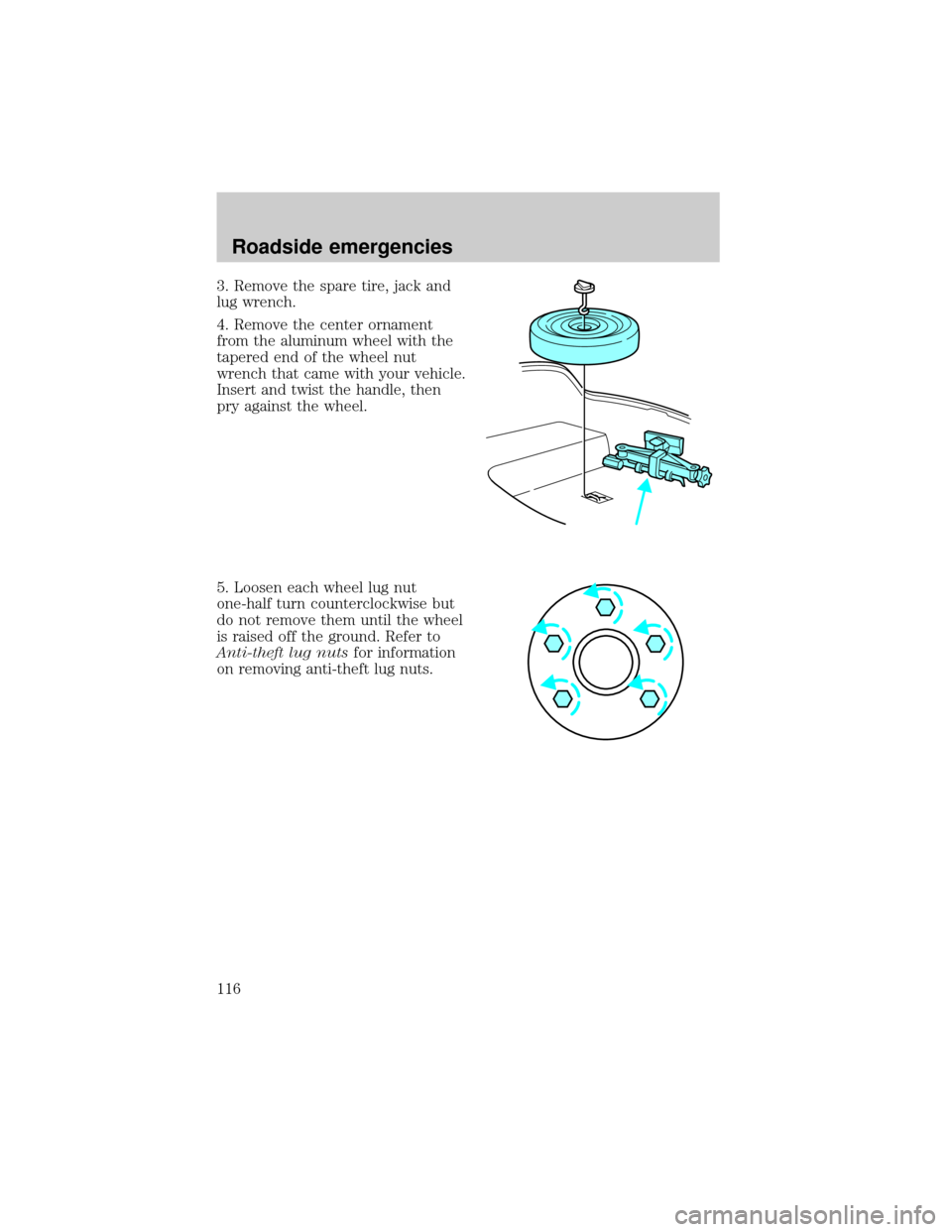
3. Remove the spare tire, jack and
lug wrench.
4. Remove the center ornament
from the aluminum wheel with the
tapered end of the wheel nut
wrench that came with your vehicle.
Insert and twist the handle, then
pry against the wheel.
5. Loosen each wheel lug nut
one-half turn counterclockwise but
do not remove them until the wheel
is raised off the ground. Refer to
Anti-theft lug nutsfor information
on removing anti-theft lug nuts.
Roadside emergencies
116
Page 116 of 170
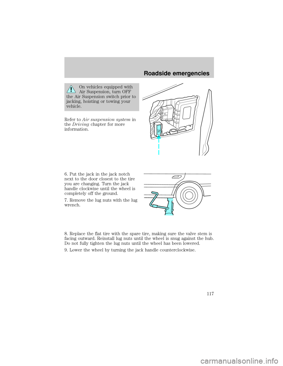
On vehicles equipped with
Air Suspension, turn OFF
the Air Suspension switch prior to
jacking, hoisting or towing your
vehicle.
Refer toAir suspension systemin
theDrivingchapter for more
information.
6. Put the jack in the jack notch
next to the door closest to the tire
you are changing. Turn the jack
handle clockwise until the wheel is
completely off the ground.
7. Remove the lug nuts with the lug
wrench.
8. Replace the flat tire with the spare tire, making sure the valve stem is
facing outward. Reinstall lug nuts until the wheel is snug against the hub.
Do not fully tighten the lug nuts until the wheel has been lowered.
9. Lower the wheel by turning the jack handle counterclockwise.
OFF
Roadside emergencies
117
Page 117 of 170
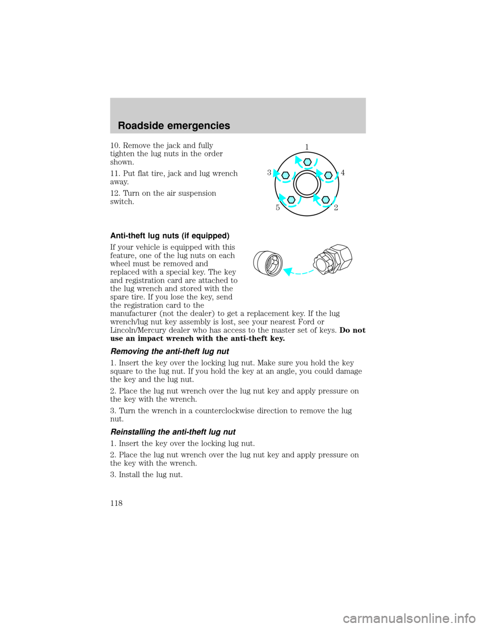
10. Remove the jack and fully
tighten the lug nuts in the order
shown.
11. Put flat tire, jack and lug wrench
away.
12. Turn on the air suspension
switch.
Anti-theft lug nuts (if equipped)
If your vehicle is equipped with this
feature, one of the lug nuts on each
wheel must be removed and
replaced with a special key. The key
and registration card are attached to
the lug wrench and stored with the
spare tire. If you lose the key, send
the registration card to the
manufacturer (not the dealer) to get a replacement key. If the lug
wrench/lug nut key assembly is lost, see your nearest Ford or
Lincoln/Mercury dealer who has access to the master set of keys.Do not
use an impact wrench with the anti-theft key.
Removing the anti-theft lug nut
1. Insert the key over the locking lug nut. Make sure you hold the key
square to the lug nut. If you hold the key at an angle, you could damage
the key and the lug nut.
2. Place the lug nut wrench over the lug nut key and apply pressure on
the key with the wrench.
3. Turn the wrench in a counterclockwise direction to remove the lug
nut.
Reinstalling the anti-theft lug nut
1. Insert the key over the locking lug nut.
2. Place the lug nut wrench over the lug nut key and apply pressure on
the key with the wrench.
3. Install the lug nut.
1
4 3
52
Roadside emergencies
118
Page 118 of 170
JUMP STARTING YOUR VEHICLE
The gases around the battery can explode if exposed to flames,
sparks, or lit cigarettes. An explosion could result in injury or
vehicle damage.
Do not push start your vehicle. You could damage the catalytic
converter.
Batteries contain sulfuric acid which burns skin, eyes, and
clothing.
Preparing your vehicle
Also see the label on the battery.
1. Use only a 12±volt supply to start your vehicle. If you connect your
battery to a 24±volt power supply you can damage your starter, ignition
system and other electrical components.
2. Do not disconnect the battery of the disabled vehicle as this could
damage the vehicle's electrical system.
3. Park the booster vehicle close to the hood of the disabled vehicle
making sure theydo nottouch. Set the parking brake on both vehicles
and stay clear of the engine cooling fan and other moving parts.
4. Check all battery terminals and remove any excessive corrosion before
you attach the battery cables.
5. Turn the heater fan on in both vehicles to protect any electrical
surges. Turn all other accessories off.
Roadside emergencies
119
Page 119 of 170
Connecting the jumper cables
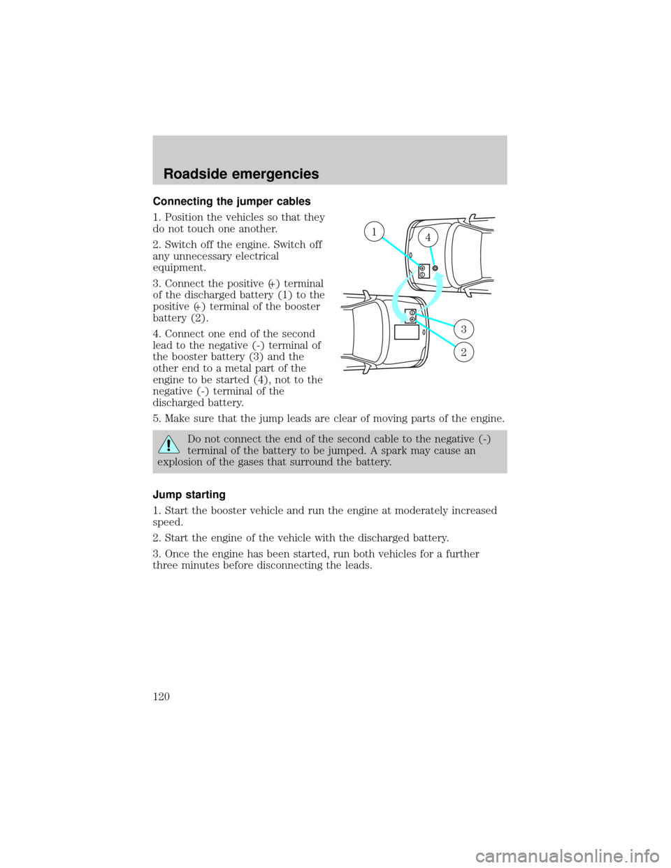
1. Position the vehicles so that they
do not touch one another.
2. Switch off the engine. Switch off
any unnecessary electrical
equipment.
3. Connect the positive (+) terminal
of the discharged battery (1) to the
positive (+) terminal of the booster
battery (2).
4. Connect one end of the second
lead to the negative (-) terminal of
the booster battery (3) and the
other end to a metal part of the
engine to be started (4), not to the
negative (-) terminal of the
discharged battery.
5. Make sure that the jump leads are clear of moving parts of the engine.
Do not connect the end of the second cable to the negative (-)
terminal of the battery to be jumped. A spark may cause an
explosion of the gases that surround the battery.
Jump starting
1. Start the booster vehicle and run the engine at moderately increased
speed.
2. Start the engine of the vehicle with the discharged battery.
3. Once the engine has been started, run both vehicles for a further
three minutes before disconnecting the leads.
+–
+–
14
3
2
Roadside emergencies
120
Page 120 of 170
Removing the jumper cables
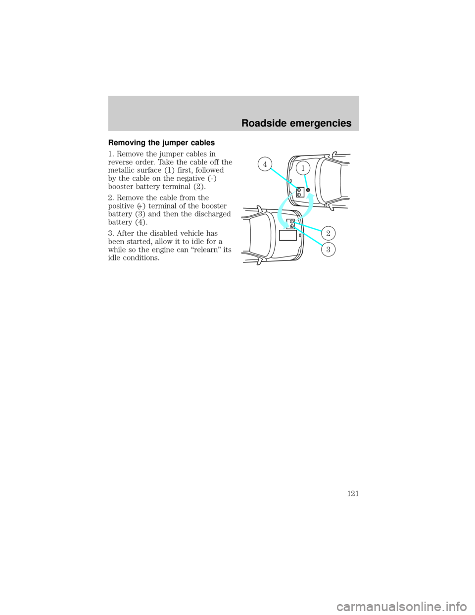
1. Remove the jumper cables in
reverse order. Take the cable off the
metallic surface (1) first, followed
by the cable on the negative (-)
booster battery terminal (2).
2. Remove the cable from the
positive (+) terminal of the booster
battery (3) and then the discharged
battery (4).
3. After the disabled vehicle has
been started, allow it to idle for a
while so the engine can ªrelearnº its
idle conditions.
+–
+–
41
2
3
Roadside emergencies
121