Boost LINCOLN MKC 2016 User Guide
[x] Cancel search | Manufacturer: LINCOLN, Model Year: 2016, Model line: MKC, Model: LINCOLN MKC 2016Pages: 432, PDF Size: 4.89 MB
Page 52 of 432
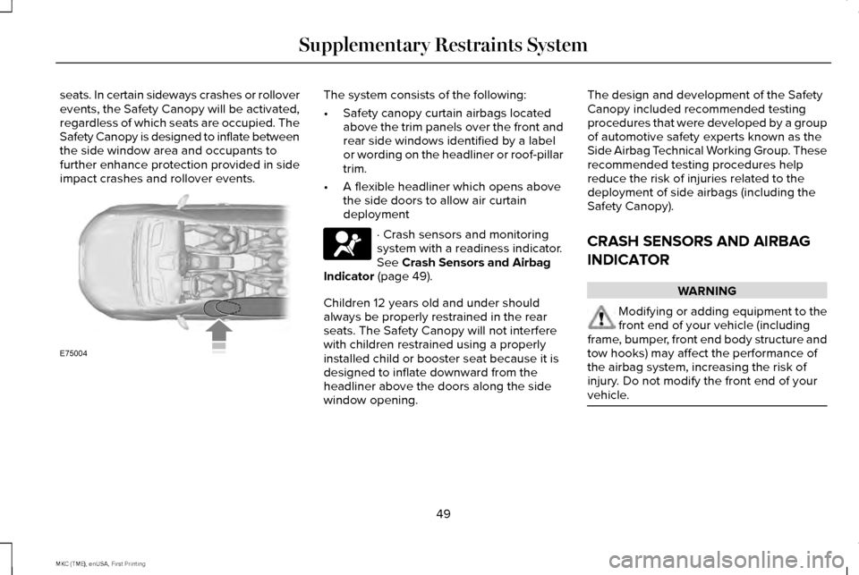
seats. In certain sideways crashes or rollover
events, the Safety Canopy will be activated,
regardless of which seats are occupied. The
Safety Canopy is designed to inflate between
the side window area and occupants to
further enhance protection provided in side
impact crashes and rollover events. The system consists of the following:
•
Safety canopy curtain airbags located
above the trim panels over the front and
rear side windows identified by a label
or wording on the headliner or roof-pillar
trim.
• A flexible headliner which opens above
the side doors to allow air curtain
deployment · Crash sensors and monitoring
system with a readiness indicator.
See Crash Sensors and Airbag
Indicator (page 49).
Children 12 years old and under should
always be properly restrained in the rear
seats. The Safety Canopy will not interfere
with children restrained using a properly
installed child or booster seat because it is
designed to inflate downward from the
headliner above the doors along the side
window opening. The design and development of the Safety
Canopy included recommended testing
procedures that were developed by a group
of automotive safety experts known as the
Side Airbag Technical Working Group. These
recommended testing procedures help
reduce the risk of injuries related to the
deployment of side airbags (including the
Safety Canopy).
CRASH SENSORS AND AIRBAG
INDICATOR
WARNING
Modifying or adding equipment to the
front end of your vehicle (including
frame, bumper, front end body structure and
tow hooks) may affect the performance of
the airbag system, increasing the risk of
injury. Do not modify the front end of your
vehicle. 49
MKC (TME), enUSA, First Printing Supplementary Restraints SystemE75004
Page 167 of 432
•
Fuels can also be harmful if absorbed
through the skin. If fuel is splashed on
the skin, clothing or both, promptly
remove contaminated clothing and wash
skin thoroughly with soap and water.
Repeated or prolonged skin contact with
fuel liquid or vapor causes skin irritation.
• Be particularly careful if you are taking
“Antabuse ” or other forms of disulfiram
for the treatment of alcoholism. Breathing
gasoline vapors, or skin contact could
cause an adverse reaction. In sensitive
individuals, serious personal injury or
sickness may result. If fuel is splashed on
the skin, promptly wash skin thoroughly
with soap and water. Consult a physician
immediately if you experience an adverse
reaction. FUEL QUALITY
Choosing the Right Fuel We recommend regular unleaded gasoline
with a pump (R+M)/2 octane rating of 87.
Some stations offer fuels posted as regular
with an octane rating below 87, particularly
in high altitude areas. We do not recommend
fuels with an octane rating below 87. To
provide improved performance, we
recommend premium fuel for severe duty
usage such as trailer tow.
Do not use any fuel other than those
recommended because they could lead to
engine damage that may not be covered by
the vehicle Warranty.Note:
Use of any fuel other than those
recommended can impair the emission
control system and cause a loss of vehicle
performance.
Do not use:
• Diesel fuel.
• Fuels containing kerosene or paraffin.
• Fuel containing more than 15% ethanol
or E85 fuel.
• Fuels containing methanol.
• Fuels containing metallic-based additives,
including manganese-based compounds.
• Fuels containing the octane booster
additive, methylcyclopentadienyl
manganese tricarbonyl (MMT).
• Leaded fuel (using leaded fuel is
prohibited by law).
The use of fuels with metallic compounds
such as methylcyclopentadienyl manganese
tricarbonyl (commonly known as MMT), which
is a manganese-based fuel additive, will
impair engine performance and affect the
emission control system.
164
MKC (TME), enUSA, First Printing Fuel and RefuelingE161513
Page 189 of 432
1.
Pull the switch and hold it in this position.
2. Drive your vehicle, then release the switch when you notice that the engine
has developed sufficient driving force.
Automatic release - drive away release
Your vehicle will automatically release the
parking brake if all of the following conditions
exist:
• The driver door is closed.
• The vehicle is accelerated.
• There are no faults detected in the
parking brake system.
Note: The driver door must be closed and
the driver safety belt must be fastened
before this feature will operate.
Note: If the electric parking brake warning
lamp stays illuminated, the electric parking
brake will not automatically release. You
must release the electric parking brake using
the electric parking brake switch.
Note: The engine must be running and the
accelerator pedal must be pressed before
the drive away release feature will operate. The brake system warning lamp will go off
to confirm that the electric parking brake has
been released.
Note:
The electric parking brake drive away
release makes starting on a hill easier. This
feature will release the parking brake
automatically when the vehicle has sufficient
drive force to move up the hill. To assure
drive away release when starting uphill,
press the accelerator pedal quickly.
Battery With No Charge WARNING
You will not be able to apply or release
the electric parking brake if the battery
is low or has no charge. If the battery is low or has no charge, use
jumper cables and a booster battery.HILL START ASSIST WARNINGS
The system does not replace the
parking brake. When you leave your
vehicle, always apply the parking brake and
shift the transmission into park (P) (automatic
transmission) or first gear (1) (manual
transmission). You must remain in your vehicle once
you have activated the system.
During all times, you are responsible
for controlling your vehicle, supervising
the system and intervening, if required. If the engine is revved excessively, or
if a malfunction is detected, the system
will be deactivated. The system makes it easier to pull away
when your vehicle is on a slope without the
need to use the parking brake.
186
MKC (TME), enUSA, First Printing Brakes
Page 257 of 432
Should your vehicle shut off after a collision,
you may restart your vehicle. For vehicles
equipped with a key system:
1. Switch off the ignition.
2. Switch on the ignition.
3. Repeat Steps 1 and 2 to re-enable the
fuel pump.
For vehicles equipped with a push button
start system:
1. Press the START/STOP button to switch
off the ignition.
2. Press the brake pedal and press the START/STOP button to switch on the
ignition.
3. Remove your foot from the brake pedal and press the
START/STOP button to
switch off the ignition.
4. You can either attempt to start the engine
by pressing the brake pedal and the
START/STOP
button, or switch on the
ignition only by pressing the
START/STOP
button without pressing
the brake pedal. Both ways re-enable the
fuel system. Note:
When you try to restart your vehicle
after a fuel shutoff, the vehicle makes sure
that various systems are safe to restart.
Once your vehicle determines that the
systems are safe, then the vehicle will allow
you to restart.
Note: In the event that your vehicle does not
restart after your third attempt, contact an
authorized dealer.
JUMP STARTING THE VEHICLE WARNINGS
The gases around the battery can
explode if exposed to flames, sparks,
or lit cigarettes. An explosion could result in
personal injury or vehicle damage. Batteries contain sulfuric acid which
can burn skin, eyes and clothing, if
contacted. Use only an adequate-sized cable with
insulated clamps. Preparing Your Vehicle
Note:
Do not attempt to push-start your
automatic transmission vehicle. Automatic
transmissions do not have push-start
capability. Attempting to push-start a vehicle
with an automatic transmission may cause
transmission damage.
Note: Use only a 12-volt supply to start your
vehicle.
Note: Do not disconnect the battery of the
disabled vehicle as this could damage the
vehicle's electrical system.
Park the booster vehicle close to the hood
of the disabled vehicle, making sure the two
vehicles do not touch. Turn all accessories
off.
254
MKC (TME), enUSA, First Printing Roadside Emergencies
Page 258 of 432

Connecting the Jumper Cables
WARNING
Do not attach the cables to fuel lines,
engine rocker covers, the intake
manifold or electrical components as
grounding points. Stay clear of moving parts.
To avoid reverse polarity connections, make
sure that you correctly identify the positive
(+) and negative (-) terminals on both the
disabled and booster vehicles before
connecting the cables. Battery positions may
vary. Note:
In the illustration, the bottom vehicle
represents the booster vehicle. 1. Connect the positive (+) jumper cable to
the positive (+) terminal of the discharged
battery. 2.
Connect the other end of the positive (+)
cable to the positive (+) terminal of the
assisting battery.
3. Connect the negative (-) cable to the negative (-) terminal of the assisting
battery. 4.
Make the final connection of the negative
(-) cable to an exposed metal part of the
stalled vehicle's engine, or connect the
negative (-) cable to the ground
connection point, if available.
255
MKC (TME), enUSA, First Printing Roadside Emergencies4
2
1
3
E142664 E152134
Page 259 of 432
WARNING
Do not connect the end of the second
cable to the negative (-) terminal of the
battery to be jumped. A spark may cause an
explosion of the gases that surround the
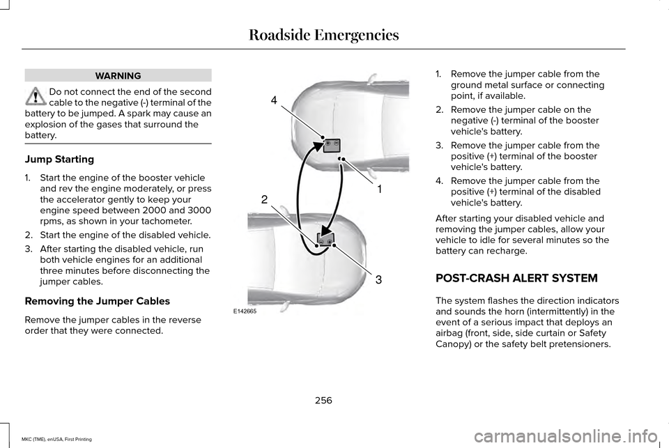
battery. Jump Starting
1. Start the engine of the booster vehicle
and rev the engine moderately, or press
the accelerator gently to keep your
engine speed between 2000 and 3000
rpms, as shown in your tachometer.
2. Start the engine of the disabled vehicle.
3. After starting the disabled vehicle, run both vehicle engines for an additional
three minutes before disconnecting the
jumper cables.
Removing the Jumper Cables
Remove the jumper cables in the reverse
order that they were connected. 1. Remove the jumper cable from the
ground metal surface or connecting
point, if available.
2. Remove the jumper cable on the negative (-) terminal of the booster
vehicle's battery.
3. Remove the jumper cable from the positive (+) terminal of the booster
vehicle's battery.
4. Remove the jumper cable from the positive (+) terminal of the disabled
vehicle's battery.
After starting your disabled vehicle and
removing the jumper cables, allow your
vehicle to idle for several minutes so the
battery can recharge.
POST-CRASH ALERT SYSTEM
The system flashes the direction indicators
and sounds the horn (intermittently) in the
event of a serious impact that deploys an
airbag (front, side, side curtain or Safety
Canopy) or the safety belt pretensioners.
256
MKC (TME), enUSA, First Printing Roadside Emergencies4
1
3
2
E142665
Page 287 of 432
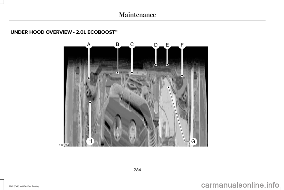
UNDER HOOD OVERVIEW - 2.0L ECOBOOST™
284
MKC (TME), enUSA, First Printing MaintenanceABCDEF
GHE171684
Page 289 of 432
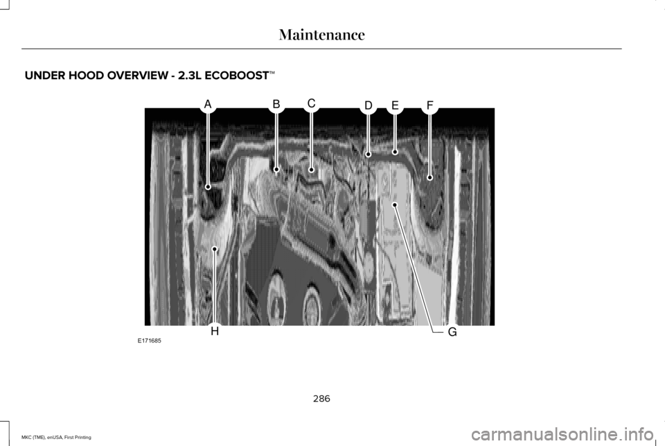
UNDER HOOD OVERVIEW - 2.3L ECOBOOST™
286
MKC (TME), enUSA, First Printing MaintenanceABCDEF
GHE171685
Page 305 of 432
CHANGING THE ENGINE AIR
FILTER
WARNING
To reduce the risk of vehicle damage
and personal burn injuries, do not start
your engine with the air cleaner removed.
Do not remove the air cleaner while the
engine is running. When changing the air filter element, use
only the air filter element listed in the
Motorcraft Parts table. See Motorcraft Parts
(page 343).
For EcoBoost equipped vehicles: When
servicing the air cleaner, it is important that
no foreign material enter the air induction
system. The engine and turbocharger are
susceptible to damage from even small
particles.
Change the air filter element at the proper
interval. See Scheduled Maintenance (page
367
). Note:
Failure to use the correct air filter
element may result in severe engine
damage. The customer warranty may be
void for any damage to the engine if the
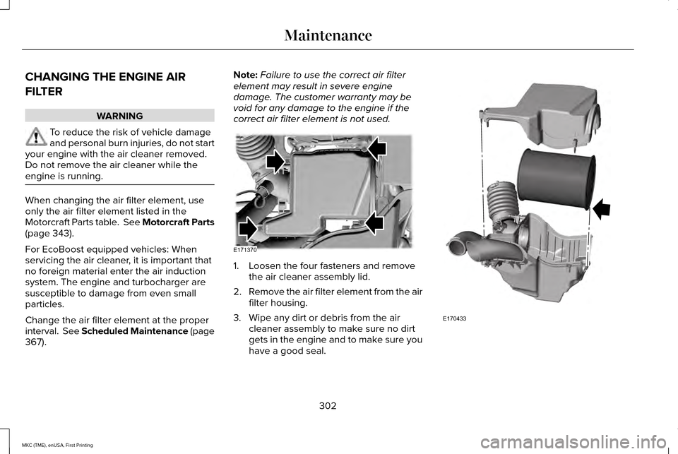
correct air filter element is not used. 1. Loosen the four fasteners and remove
the air cleaner assembly lid.
2. Remove the air filter element from the air
filter housing.
3. Wipe any dirt or debris from the air cleaner assembly to make sure no dirt
gets in the engine and to make sure you
have a good seal. 302
MKC (TME), enUSA, First Printing MaintenanceE171370 E170433
Page 345 of 432
ENGINE SPECIFICATIONS
2.3L EcoBoost engine
2.0L EcoBoost engine
Engine
138
122
Cubic inches
9.5:1
9.3:1
Compression ratio
0.027-0.031 in. (0.70-0.80 mm)
0.027-0.031 in. (0.70-0.80 mm)
Spark plug gap
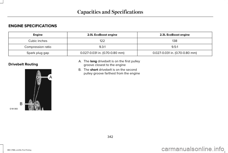
Drivebelt Routing A. The long drivebelt is on the first pulley
groove closest to the engine
B. The
short drivebelt is on the second
pulley groove farthest from the engine
342
MKC (TME), enUSA, First Printing Capacities and SpecificationsE161383
A
B