light LINCOLN MKC 2016 Repair Manual
[x] Cancel search | Manufacturer: LINCOLN, Model Year: 2016, Model line: MKC, Model: LINCOLN MKC 2016Pages: 432, PDF Size: 4.89 MB
Page 208 of 432
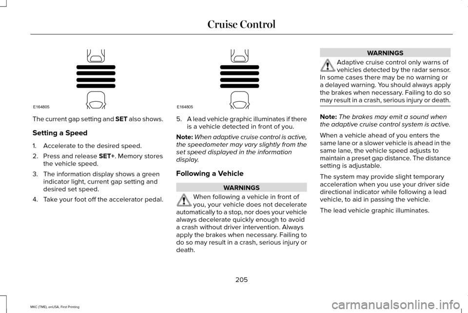
The current gap setting and SET also shows.
Setting a Speed
1. Accelerate to the desired speed.
2. Press and release SET+. Memory stores
the vehicle speed.
3. The information display shows a green indicator light, current gap setting and
desired set speed.
4. Take your foot off the accelerator pedal. 5.
A lead vehicle graphic illuminates if there
is a vehicle detected in front of you.
Note: When adaptive cruise control is active,
the speedometer may vary slightly from the
set speed displayed in the information
display.
Following a Vehicle WARNINGS
When following a vehicle in front of
you, your vehicle does not decelerate
automatically to a stop, nor does your vehicle
always decelerate quickly enough to avoid
a crash without driver intervention. Always
apply the brakes when necessary. Failing to
do so may result in a crash, serious injury or
death. WARNINGS
Adaptive cruise control only warns of
vehicles detected by the radar sensor.
In some cases there may be no warning or
a delayed warning. You should always apply
the brakes when necessary. Failing to do so
may result in a crash, serious injury or death. Note:
The brakes may emit a sound when
the adaptive cruise control system is active.
When a vehicle ahead of you enters the
same lane or a slower vehicle is ahead in the
same lane, the vehicle speed adjusts to
maintain a preset gap distance. The distance
setting is adjustable.
The system may provide slight temporary
acceleration when you use your driver side
directional indicator while following a lead
vehicle, to aid in passing the vehicle.
The lead vehicle graphic illuminates.
205
MKC (TME), enUSA, First Printing Cruise ControlE164805 E164805
Page 210 of 432
Adaptive cruise control, distance between vehicle settings
Dynamic behavior
Distance gap
Time gap, seconds
Graphic display, bars indic-
ated between vehicles
Set speed
yd (m)
mph ( km/h)
Sport.
31 (28)
1
1
62 (100)
Normal.
43 (39)
1.4
2
62 (100)
Normal.
55 (50)
1.8
3
62 (100)
Comfort.
67 (61)
2.2
4
62 (100)
Each time you start the vehicle, the system
selects the last chosen gap for the current
driver.
Disengaging the System
Press the brake pedal or press CNCL. The
last set speed displays in grey but does not
erase. Overriding the System WARNING
Whenever you press the accelerator
pedal and override the system, the
system does not automatically apply the
brakes to maintain separation from any
vehicle ahead. While you press the accelerator pedal, you
override the set speed and gap distance. When you override the system, the
green indicator light illuminates
and the lead vehicle graphic does
not show in the information display.
The system resumes operation when you
release the accelerator pedal. The vehicle
speed decreases to the set speed, or a lower
speed if following a slower vehicle.
207
MKC (TME), enUSA, First Printing Cruise ControlE144529
Page 215 of 432
The cruise control indicator light
replaces the adaptive cruise
control indicator light if you select
normal cruise control. The gap setting does
not display, the system does not
automatically respond to lead vehicles and
automatic braking is not active. The system
remembers the last setting when you start
your vehicle.
212
MKC (TME), enUSA, First Printing Cruise ControlE71340
Page 217 of 432
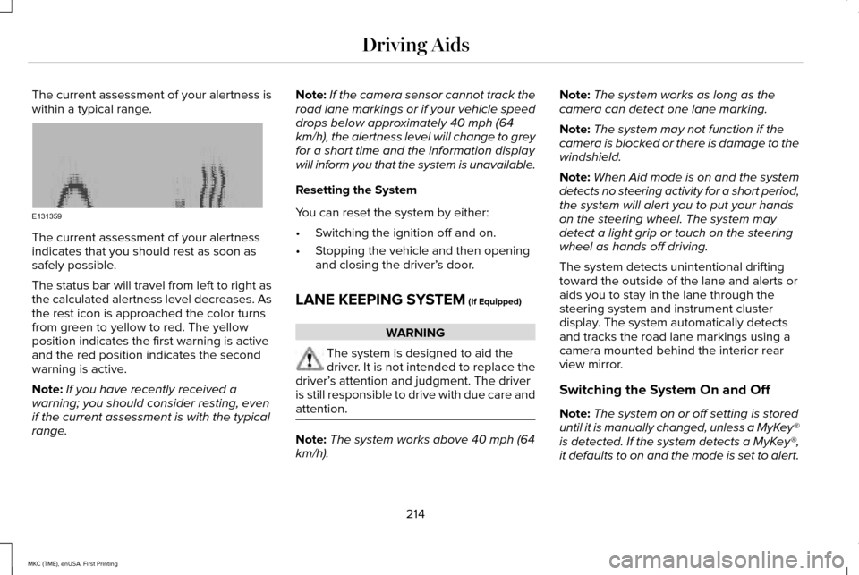
The current assessment of your alertness is
within a typical range.
The current assessment of your alertness
indicates that you should rest as soon as
safely possible.
The status bar will travel from left to right as
the calculated alertness level decreases. As
the rest icon is approached the color turns
from green to yellow to red. The yellow
position indicates the first warning is active
and the red position indicates the second
warning is active.
Note:
If you have recently received a
warning; you should consider resting, even
if the current assessment is with the typical
range. Note:
If the camera sensor cannot track the
road lane markings or if your vehicle speed
drops below approximately 40 mph (64
km/h), the alertness level will change to grey
for a short time and the information display
will inform you that the system is unavailable.
Resetting the System
You can reset the system by either:
• Switching the ignition off and on.
• Stopping the vehicle and then opening
and closing the driver’ s door.
LANE KEEPING SYSTEM (If Equipped) WARNING
The system is designed to aid the
driver. It is not intended to replace the
driver’ s attention and judgment. The driver
is still responsible to drive with due care and
attention. Note:
The system works above 40 mph (64
km/h). Note:
The system works as long as the
camera can detect one lane marking.
Note: The system may not function if the
camera is blocked or there is damage to the
windshield.
Note: When Aid mode is on and the system
detects no steering activity for a short period,
the system will alert you to put your hands
on the steering wheel. The system may
detect a light grip or touch on the steering
wheel as hands off driving.
The system detects unintentional drifting
toward the outside of the lane and alerts or
aids you to stay in the lane through the
steering system and instrument cluster
display. The system automatically detects
and tracks the road lane markings using a
camera mounted behind the interior rear
view mirror.
Switching the System On and Off
Note: The system on or off setting is stored
until it is manually changed, unless a MyKey®
is detected. If the system detects a MyKey®,
it defaults to on and the mode is set to alert.
214
MKC (TME), enUSA, First Printing Driving AidsE131359
Page 220 of 432
•
Using the turn signal indicator. •Evasive steering maneuver.
Troubleshooting Why is the feature not available (line markings are gray) when I can s\
ee the lane markings on the road?
Vehicle speed is outside the operational range of the feature
Sun is shining directly into the camera lens
Quick intentional lane change
Staying too close to the lane marking
Driving at high speeds in curves
Previous feature activation happened within the last one second
Ambiguous lane markings (mainly in construction zones)
Rapid transition from light to dark or vice versa
Sudden offset in lane markings
ABS or AdvanceTrac activation
Camera blockage due to dirt, grime, fog, frost or water on the windshield
Driving too close to the vehicle in front of you
Transitioning between no lane markings to lane markings or vice versa
Standing water on the road
217
MKC (TME), enUSA, First Printing Driving Aids
Page 222 of 432
BLIND SPOT INFORMATION
SYSTEM
WARNING
To help avoid injuries, NEVER use the
Blind Spot Information System as a
replacement for using the interior and
exterior mirrors or looking over your shoulder
before changing lanes. The Blind Spot
Information System is not a replacement for
careful driving. The Blind Spot Information System is
designed to aid you in detecting vehicles
that may have entered the blind spot zone
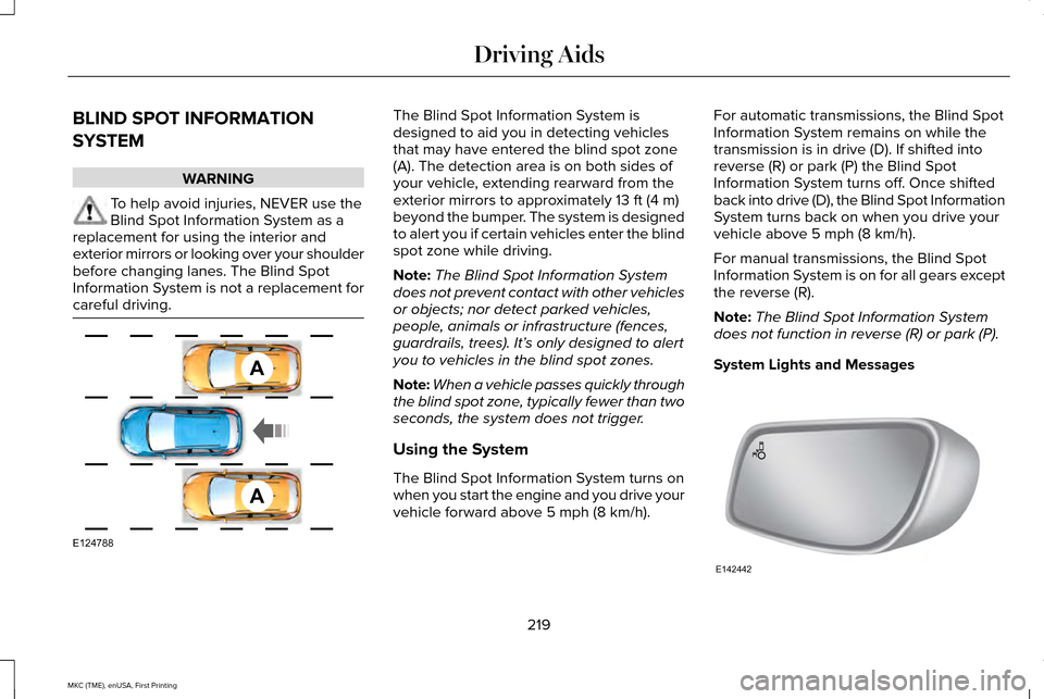
(A). The detection area is on both sides of
your vehicle, extending rearward from the
exterior mirrors to approximately 13 ft (4 m)
beyond the bumper. The system is designed
to alert you if certain vehicles enter the blind
spot zone while driving.
Note: The Blind Spot Information System
does not prevent contact with other vehicles
or objects; nor detect parked vehicles,
people, animals or infrastructure (fences,
guardrails, trees). It’ s only designed to alert
you to vehicles in the blind spot zones.
Note: When a vehicle passes quickly through
the blind spot zone, typically fewer than two
seconds, the system does not trigger.
Using the System
The Blind Spot Information System turns on
when you start the engine and you drive your
vehicle forward above
5 mph (8 km/h). For automatic transmissions, the Blind Spot
Information System remains on while the
transmission is in drive (D). If shifted into
reverse (R) or park (P) the Blind Spot
Information System turns off. Once shifted
back into drive (D), the Blind Spot Information
System turns back on when you drive your
vehicle above
5 mph (8 km/h).
For manual transmissions, the Blind Spot
Information System is on for all gears except
the reverse (R).
Note: The Blind Spot Information System
does not function in reverse (R) or park (P).
System Lights and Messages 219
MKC (TME), enUSA, First Printing Driving AidsA
A
E124788 E142442
Page 227 of 432
System Lights, Messages and Audible
Alerts
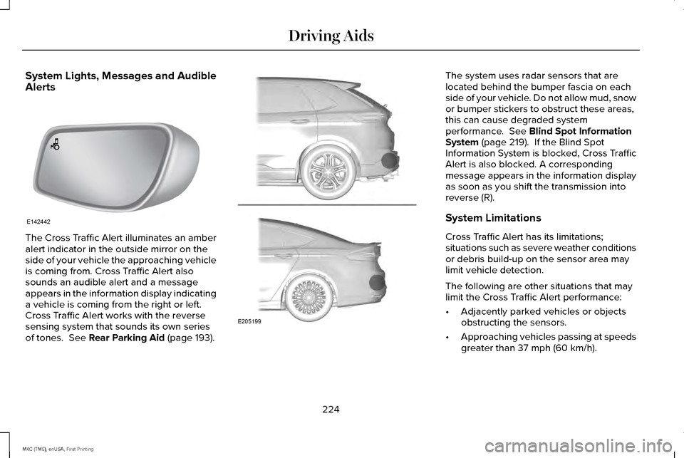
The Cross Traffic Alert illuminates an amber
alert indicator in the outside mirror on the
side of your vehicle the approaching vehicle
is coming from. Cross Traffic Alert also
sounds an audible alert and a message
appears in the information display indicating
a vehicle is coming from the right or left.
Cross Traffic Alert works with the reverse
sensing system that sounds its own series
of tones. See Rear Parking Aid (page 193). The system uses radar sensors that are
located behind the bumper fascia on each
side of your vehicle. Do not allow mud, snow
or bumper stickers to obstruct these areas,
this can cause degraded system
performance.
See Blind Spot Information
System (page 219). If the Blind Spot
Information System is blocked, Cross Traffic
Alert is also blocked. A corresponding
message appears in the information display
as soon as you shift the transmission into
reverse (R).
System Limitations
Cross Traffic Alert has its limitations;
situations such as severe weather conditions
or debris build-up on the sensor area may
limit vehicle detection.
The following are other situations that may
limit the Cross Traffic Alert performance:
• Adjacently parked vehicles or objects
obstructing the sensors.
• Approaching vehicles passing at speeds
greater than
37 mph (60 km/h).
224
MKC (TME), enUSA, First Printing Driving AidsE142442 E205199
Page 230 of 432
The system alerts you of certain collision
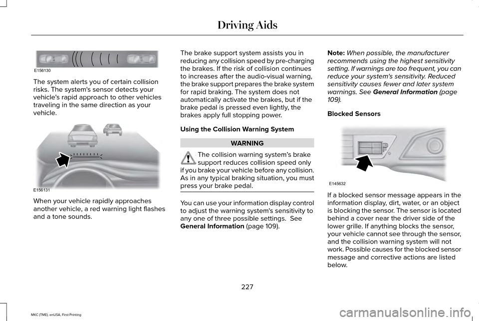
risks. The system's sensor detects your
vehicle's rapid approach to other vehicles
traveling in the same direction as your
vehicle.
When your vehicle rapidly approaches
another vehicle, a red warning light flashes
and a tone sounds. The brake support system assists you in
reducing any collision speed by pre-charging
the brakes. If the risk of collision continues
to increases after the audio-visual warning,
the brake support prepares the brake system
for rapid braking. The system does not
automatically activate the brakes, but if the
brake pedal is pressed even lightly, the
brakes apply full stopping power.
Using the Collision Warning System
WARNING
The collision warning system
’s brake
support reduces collision speed only
if you brake your vehicle before any collision.
As in any typical braking situation, you must
press your brake pedal. You can use your information display control
to adjust the warning system's sensitivity to
any one of three possible settings. See
General Information (page 109). Note:
When possible, the manufacturer
recommends using the highest sensitivity
setting. If warnings are too frequent, you can
reduce your system's sensitivity. Reduced
sensitivity causes fewer and later system
warnings.
See General Information (page
109).
Blocked Sensors If a blocked sensor message appears in the
information display, dirt, water, or an object
is blocking the sensor. The sensor is located
behind a cover near the driver side of the
lower grille. If anything blocks the sensor,
your vehicle cannot see through the sensor,
and the collision warning system will not
work. Possible causes for the blocked sensor
message and corrective actions are listed
below.
227
MKC (TME), enUSA, First Printing Driving AidsE156130 E156131 E145632
Page 243 of 432
TOWING A TRAILER
WARNINGS
Do not exceed the GVWR or the
GAWR specified on the certification
label. Towing trailers beyond the
maximum recommended gross
trailer weight exceeds the limit of the
vehicle and could result in engine
damage, transmission damage,
structural damage, loss of vehicle
control, vehicle rollover and personal
injury. Your vehicle may have electrical items,
such as fuses or relays, related to
towing. See the Fuses chapter. Your vehicle's load capacity designation
is by weight, not by volume, so you
cannot necessarily use all available
space when loading a vehicle or trailer.
Towing a trailer places an extra load on
your vehicle's engine, transmission, axle,
brakes, tires and suspension. Inspect
these components periodically during,
and after, any towing operation.
Load Placement
To help minimize how trailer movement
affects your vehicle when driving:
•
Load the heaviest items closest to
the trailer floor.
• Load the heaviest items centered
between the left and right side trailer
tires. •
Load the heaviest items above the
trailer axles or just slightly forward
toward the trailer tongue. Do not
allow the final trailer tongue weight
to go above or below 10-15% of the
loaded trailer weight.
• Select a tow bar with the correct rise
or drop. When both the loaded
vehicle and trailer are connected, the
trailer frame should be level, or
slightly angled down toward your
vehicle, when viewed from the side.
When driving with a trailer or payload, a
slight takeoff vibration or shudder may
be present due to the increased payload
weight. Additional information regarding
proper trailer loading and setting your
vehicle up for towing is located in
another chapter of this manual. See
Load Limit (page 232).
You can also find information in the
RV
& Trailer Towing Guide available at your
authorized dealer, or online.
240
MKC (TME), enUSA, First Printing Towing
Page 247 of 432
ESSENTIAL TOWING CHECKS
Follow these guidelines for safe towing:
•
Do not tow a trailer until you drive your
vehicle at least 1000 miles (1600
kilometers).
• Consult your local motor vehicle laws for
towing a trailer.
• See the instructions included with towing
accessories for the proper installation
and adjustment specifications.
• Service your vehicle more frequently if
you tow a trailer. See your scheduled
maintenance information.
• If you use a rental trailer, follow the
instructions the rental agency gives you.
You can find information on load
specification terms found on the tire label
and Safety Compliance label as well as
instructions on calculating your vehicle's load
in the Load Carrying chapter. See Load Limit
(page 232).
Remember to account for the trailer tongue
weight as part of your vehicle load when
calculating the total vehicle weight. Hitches
Do not use a hitch that either clamps onto
the bumper or attaches to the axle.
Distribute the trailer load so 10-15% of the
total trailer weight is on the tongue.
Weight-distributing Hitches
WARNING
Do not adjust a weight-distributing
hitch to any position where the rear
bumper of the vehicle is higher than it was
before attaching the trailer. Doing so will
defeat the function of the weight-distributing
hitch, which may cause unpredictable
handling, and could result in serious personal
injury. When hooking-up a trailer using a
weight-distributing hitch, always use the
following procedure:
1. Park the loaded vehicle, without the
trailer, on a level surface.
2. Measure the height to the top of your vehicle's front wheel opening on the
fender. This is H1. 3. Attach the loaded trailer to your vehicle
without the weight-distributing bars
connected.
4. Measure the height to the top of your vehicle's front wheel opening on the
fender a second time. This is H2.
5. Install and adjust the tension in the weight-distributing bars so that the height
of your vehicle's front wheel opening on
the fender is approximately half the way
down from H2, toward H1.
6. Check that the trailer is level or slightly nose down toward your vehicle. If not,
adjust the ball height accordingly and
repeat Steps 2-6.
When the trailer is level or slightly nose down
toward the vehicle:
• Lock the bar tension adjuster in place.
• Check that the trailer tongue securely
attaches and locks onto the hitch.
• Install safety chains, lighting, and trailer
brake controls as required by law or the
trailer manufacturer.
244
MKC (TME), enUSA, First Printing Towing