Engine LINCOLN MKC 2016 Manual PDF
[x] Cancel search | Manufacturer: LINCOLN, Model Year: 2016, Model line: MKC, Model: LINCOLN MKC 2016Pages: 432, PDF Size: 4.89 MB
Page 257 of 432
Should your vehicle shut off after a collision,
you may restart your vehicle. For vehicles
equipped with a key system:
1. Switch off the ignition.
2. Switch on the ignition.
3. Repeat Steps 1 and 2 to re-enable the
fuel pump.
For vehicles equipped with a push button
start system:
1. Press the START/STOP button to switch
off the ignition.
2. Press the brake pedal and press the START/STOP button to switch on the
ignition.
3. Remove your foot from the brake pedal and press the
START/STOP button to
switch off the ignition.
4. You can either attempt to start the engine
by pressing the brake pedal and the
START/STOP
button, or switch on the
ignition only by pressing the
START/STOP
button without pressing
the brake pedal. Both ways re-enable the
fuel system. Note:
When you try to restart your vehicle
after a fuel shutoff, the vehicle makes sure
that various systems are safe to restart.
Once your vehicle determines that the
systems are safe, then the vehicle will allow
you to restart.
Note: In the event that your vehicle does not
restart after your third attempt, contact an
authorized dealer.
JUMP STARTING THE VEHICLE WARNINGS
The gases around the battery can
explode if exposed to flames, sparks,
or lit cigarettes. An explosion could result in
personal injury or vehicle damage. Batteries contain sulfuric acid which
can burn skin, eyes and clothing, if
contacted. Use only an adequate-sized cable with
insulated clamps. Preparing Your Vehicle
Note:
Do not attempt to push-start your
automatic transmission vehicle. Automatic
transmissions do not have push-start
capability. Attempting to push-start a vehicle
with an automatic transmission may cause
transmission damage.
Note: Use only a 12-volt supply to start your
vehicle.
Note: Do not disconnect the battery of the
disabled vehicle as this could damage the
vehicle's electrical system.
Park the booster vehicle close to the hood
of the disabled vehicle, making sure the two
vehicles do not touch. Turn all accessories
off.
254
MKC (TME), enUSA, First Printing Roadside Emergencies
Page 258 of 432

Connecting the Jumper Cables
WARNING
Do not attach the cables to fuel lines,
engine rocker covers, the intake
manifold or electrical components as
grounding points. Stay clear of moving parts.
To avoid reverse polarity connections, make
sure that you correctly identify the positive
(+) and negative (-) terminals on both the
disabled and booster vehicles before
connecting the cables. Battery positions may
vary. Note:
In the illustration, the bottom vehicle
represents the booster vehicle. 1. Connect the positive (+) jumper cable to
the positive (+) terminal of the discharged
battery. 2.
Connect the other end of the positive (+)
cable to the positive (+) terminal of the
assisting battery.
3. Connect the negative (-) cable to the negative (-) terminal of the assisting
battery. 4.
Make the final connection of the negative
(-) cable to an exposed metal part of the
stalled vehicle's engine, or connect the
negative (-) cable to the ground
connection point, if available.
255
MKC (TME), enUSA, First Printing Roadside Emergencies4
2
1
3
E142664 E152134
Page 259 of 432
WARNING
Do not connect the end of the second
cable to the negative (-) terminal of the
battery to be jumped. A spark may cause an
explosion of the gases that surround the
battery. Jump Starting
1. Start the engine of the booster vehicle
and rev the engine moderately, or press
the accelerator gently to keep your
engine speed between 2000 and 3000
rpms, as shown in your tachometer.
2. Start the engine of the disabled vehicle.
3. After starting the disabled vehicle, run both vehicle engines for an additional
three minutes before disconnecting the
jumper cables.
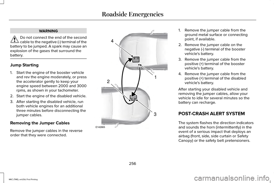
Removing the Jumper Cables
Remove the jumper cables in the reverse
order that they were connected. 1. Remove the jumper cable from the
ground metal surface or connecting
point, if available.
2. Remove the jumper cable on the negative (-) terminal of the booster
vehicle's battery.
3. Remove the jumper cable from the positive (+) terminal of the booster
vehicle's battery.
4. Remove the jumper cable from the positive (+) terminal of the disabled
vehicle's battery.
After starting your disabled vehicle and
removing the jumper cables, allow your
vehicle to idle for several minutes so the
battery can recharge.
POST-CRASH ALERT SYSTEM
The system flashes the direction indicators
and sounds the horn (intermittently) in the
event of a serious impact that deploys an
airbag (front, side, side curtain or Safety
Canopy) or the safety belt pretensioners.
256
MKC (TME), enUSA, First Printing Roadside Emergencies4
1
3
2
E142665
Page 265 of 432
If you cannot find unleaded fuel or can only
get fuel with an anti-knock index lower than
is recommended for your vehicle, contact
our Customer Relationship Center.
The use of leaded fuel in your vehicle without
proper conversion may damage the
effectiveness of your emission control system
and may cause engine knocking or serious
engine damage. Ford Motor Company or
Ford of Canada is not responsible for any
damage caused by use of improper fuel.
Using leaded fuel may also result in difficulty
importing your vehicle back into the United
States.
If your vehicle must be serviced while you
are traveling or living in Asia-Pacific Region,
Sub-Saharan Africa, U.S. Virgin Islands,
Central America, the Caribbean, and Israel,
contact the nearest authorized dealer. If the
authorized dealer cannot help you, contact:
FORD MOTOR COMPANY
Customer Relationship Center
1555 Fairlane Drive
Fairlane Business Park #3
Allen Park, Michigan 48101
U.S.A.
Telephone: (313) 594-4857
Fax: (313) 390-0804
Email: [email protected]
For customers in Guam, the Commonwealth
of the Northern Mariana Islands (CNMI),
America Samoa, and the U.S. Virgin Islands,
please feel free to call our Toll-Free Number:
(800) 841-FORD (3673).
If your vehicle must be serviced while you
are traveling or living in Puerto Rico, contact
the nearest authorized dealer. If the
authorized dealer cannot help you, contact:
FORD MOTOR COMPANY
Customer Relationship Center
1555 Fairlane Drive
Fairlane Business Park #3
Allen Park, Michigan 48101
U.S.A.
Telephone: (800) 841-FORD (3673)
FAX: (313) 390-0804
Email: [email protected]
www.ford.com.pr
If your vehicle must be serviced while you
are traveling or living in the Middle East,
contact the nearest authorized dealer. If the
authorized dealer cannot help you, contact:
FORD MOTOR COMPANY
Customer Relationship Center
1555 Fairlane Drive
Fairlane Business Park #3
Allen Park, Michigan 48101
U.S.A.
Ford: 80004443673
Lincoln: 80004441067
If calling from the UAE: 80004441066
If calling from the Kingdom of Saudi Arabia:
8008443673
If calling from Kuwait:
22280384
262
MKC (TME), enUSA, First Printing Customer Assistance
Page 268 of 432
FUSE SPECIFICATION CHART
Pre-Fuse Box
The pre-fuse box is in the engine
compartment attached to the positive battery
post. This box contains several high current
fuses. If you need to replace one of these
high current fuses, see an authorized dealer.
Power Distribution Box WARNINGS
Always disconnect the battery before
servicing high current fuses.
To reduce risk of electrical shock,
always replace the cover to the power
distribution box before reconnecting the
battery or refilling fluid reservoirs. The power distribution box is in the engine
compartment. It has high-current fuses that
protect your vehicle's main electrical systems
from overloads.
You will need to reset some features if you
disconnect and reconnect the battery. See
Changing the 12V Battery (page 294).
Lift the release lever at the rear of the cover
to remove it.
265
MKC (TME), enUSA, First Printing Fuses
Page 272 of 432
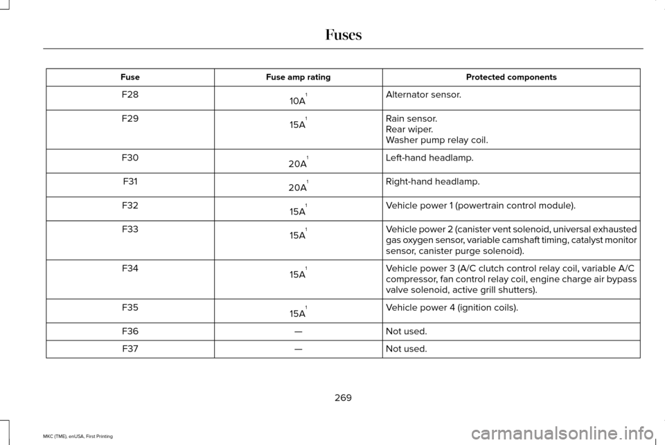
Protected components
Fuse amp rating
Fuse
Alternator sensor.
10A 1
F28
Rain sensor.
15A 1
F29
Rear wiper.
Washer pump relay coil.
Left-hand headlamp.
20A 1
F30
Right-hand headlamp.
20A 1
F31
Vehicle power 1 (powertrain control module).
15A 1
F32
Vehicle power 2 (canister vent solenoid, universal exhausted
gas oxygen sensor, variable camshaft timing, catalyst monitor
sensor, canister purge solenoid).
15A
1
F33
Vehicle power 3 (A/C clutch control relay coil, variable A/C
compressor, fan control relay coil, engine charge air bypass
valve solenoid, active grill shutters).
15A
1
F34
Vehicle power 4 (ignition coils).
15A 1
F35
Not used.
—
F36
Not used.
—
F37
269
MKC (TME), enUSA, First Printing Fuses
Page 285 of 432
GENERAL INFORMATION
Have your vehicle serviced regularly to help
maintain its roadworthiness and resale value.
There is a large network of authorized
dealers that are there to help you with their
professional servicing expertise. We believe
that their specially trained technicians are
best qualified to service your vehicle properly
and expertly. They are supported by a wide
range of highly specialized tools developed
specifically for servicing your vehicle.
To help you service your vehicle, we provide
scheduled maintenance information which
makes tracking routine service easy. See
Scheduled Maintenance (page 367).
If your vehicle requires professional service,
an authorized dealer can provide the
necessary parts and service. Check your
warranty information to find out which parts
and services are covered.
Use only recommended fuels, lubricants,
fluids and service parts conforming to
specifications. Motorcraft® parts are
designed and built to provide the best
performance in your vehicle. Precautions
•
Do not work on a hot engine.
• Make sure that nothing gets caught in
moving parts.
• Do not work on a vehicle with the engine
running in an enclosed space, unless you
are sure you have enough ventilation.
• Keep all open flames and other burning
material (such as cigarettes) away from
the battery and all fuel related parts.
Working with the Engine Off
1. Set the parking brake and shift to park (P).
2. Switch off the engine.
3. Block the wheels.
Working with the Engine On WARNING
To reduce the risk of vehicle damage
and/or personal burn injuries, do not
start your engine with the air cleaner
removed and do not remove it while the
engine is running. 1. Set the parking brake and shift to park
(P).
2. Block the wheels
OPENING AND CLOSING THE
HOOD
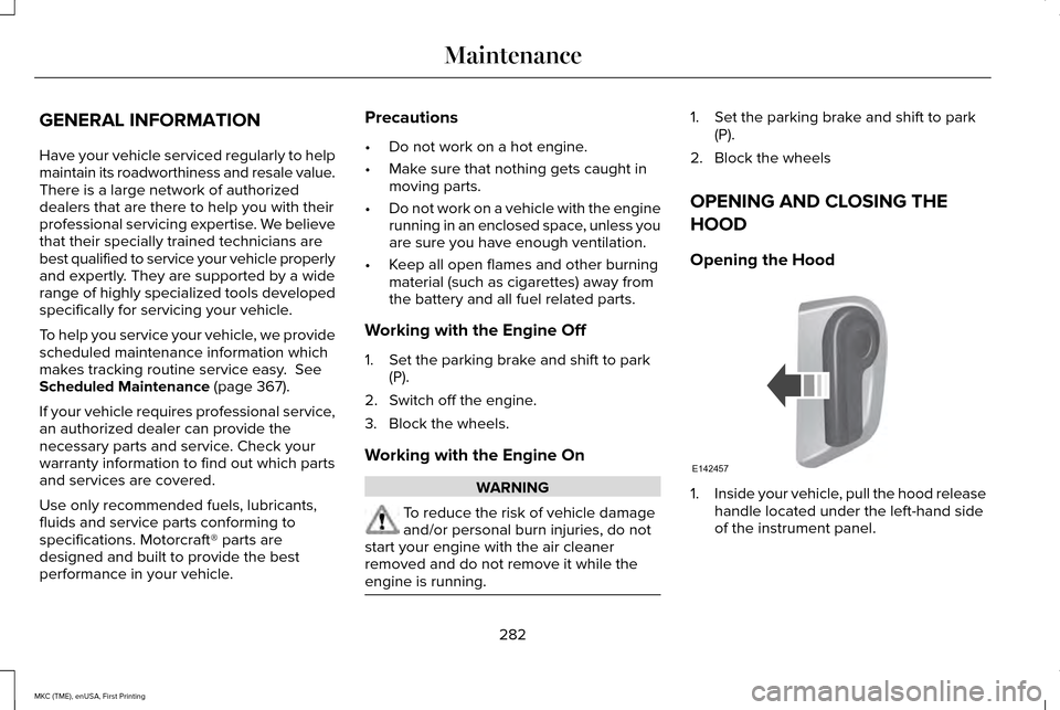
Opening the Hood 1.
Inside your vehicle, pull the hood release
handle located under the left-hand side
of the instrument panel.
282
MKC (TME), enUSA, First Printing MaintenanceE142457
Page 288 of 432
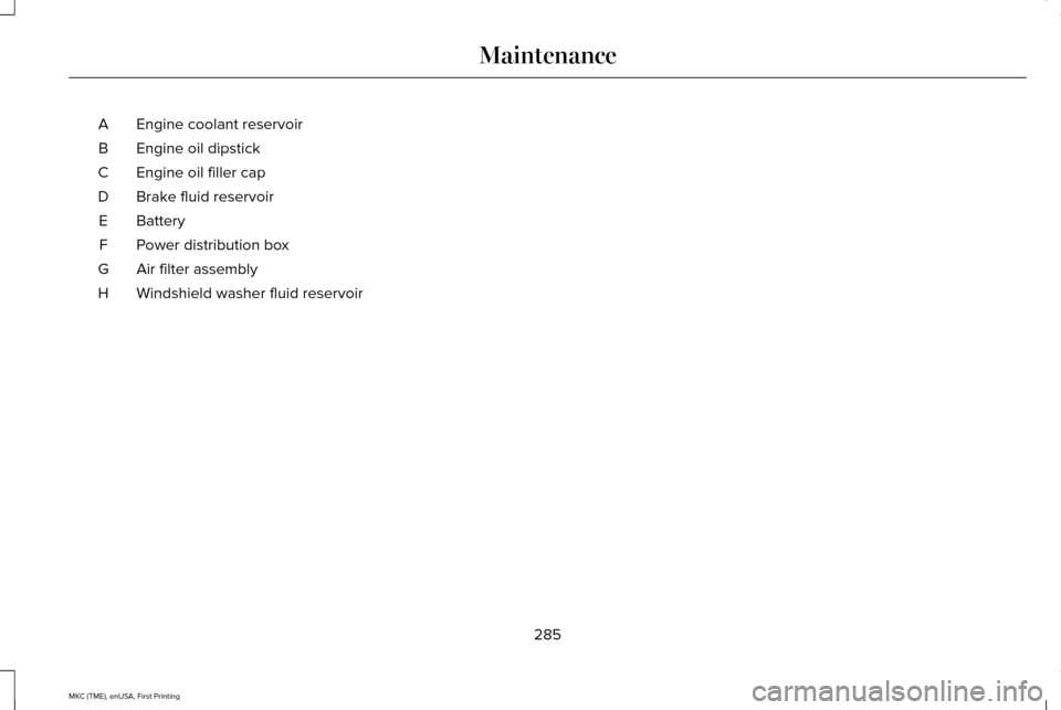
Engine coolant reservoir
A
Engine oil dipstick
B
Engine oil filler cap
C
Brake fluid reservoir
D
Battery
E
Power distribution box
F
Air filter assembly
G
Windshield washer fluid reservoir
H
285
MKC (TME), enUSA, First Printing Maintenance
Page 290 of 432
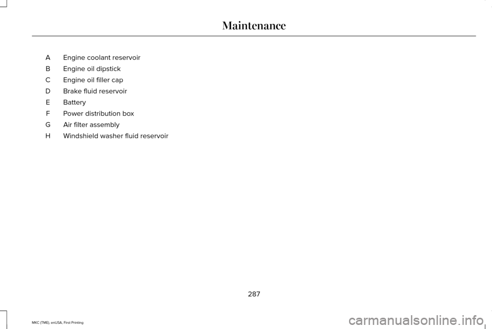
Engine coolant reservoir
A
Engine oil dipstick
B
Engine oil filler cap
C
Brake fluid reservoir
D
Battery
E
Power distribution box
F
Air filter assembly
G
Windshield washer fluid reservoir
H
287
MKC (TME), enUSA, First Printing Maintenance
Page 291 of 432

ENGINE OIL DIPSTICK
MINA
MAXB
ENGINE OIL CHECK
1. Make sure that your vehicle is on level ground.
2. Check the oil level before starting the engine, or switch the engine off and wait
15 minutes for the oil to drain into the oil
pan. 3. Remove the dipstick and wipe it with a
clean, lint free cloth. Replace the dipstick
and remove it again to check the oil level.
If the oil level is at the minimum mark, add
oil immediately. See Capacities and
Specifications (page 342).
Do not use supplemental engine oil additives
because they are unnecessary and could
lead to engine damage that may not be
covered by your vehicle warranty.
Note: Make sure that the oil level is between
the minimum and the maximum marks.
Note: The oil consumption of new engines
reaches its normal level after approximately
3,000 mi (5,000 km)
. Adding Engine Oil Only use oils certified for gasoline engines
by the American Petroleum Institute (API).
An oil with this trademark symbol conforms
to the current engine and emission system
protection standards and fuel economy
requirements of the International Lubricants
Specification Advisory Council (ILSAC),
comprised of U.S. and Japanese automobile
manufacturers.
WARNINGS
Only add oil when the engine is cold.
If the engine is hot, wait 10 minutes for
the engine to cool down.
288
MKC (TME), enUSA, First Printing MaintenanceE170468
AB E142732