clock LINCOLN MKC 2017 Owners Manual
[x] Cancel search | Manufacturer: LINCOLN, Model Year: 2017, Model line: MKC, Model: LINCOLN MKC 2017Pages: 538, PDF Size: 4.8 MB
Page 33 of 538
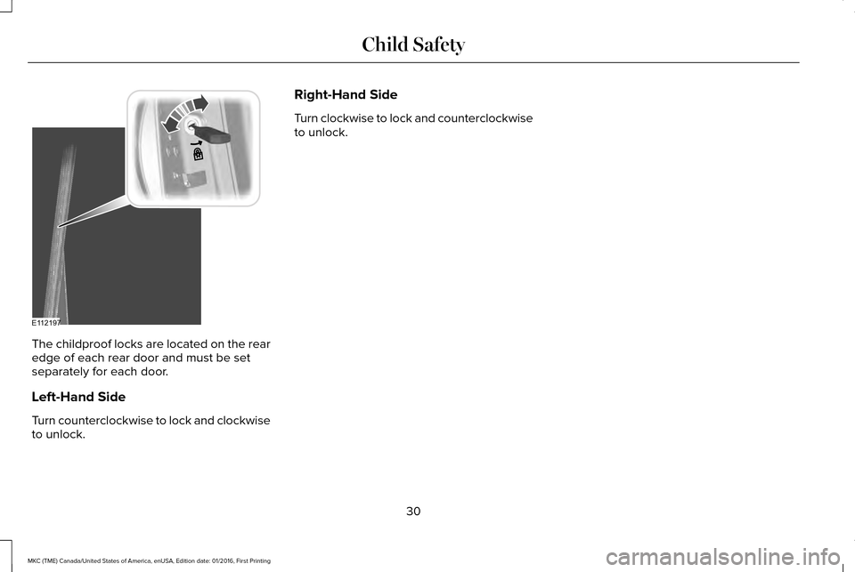
The childproof locks are located on the rear
edge of each rear door and must be set
separately for each door.
Left-Hand Side
Turn counterclockwise to lock and clockwise
to unlock. Right-Hand Side
Turn clockwise to lock and counterclockwise
to unlock.
30
MKC (TME) Canada/United States of America, enUSA, Edition date: 01/2016, First Printing Child SafetyE112197
Page 68 of 538
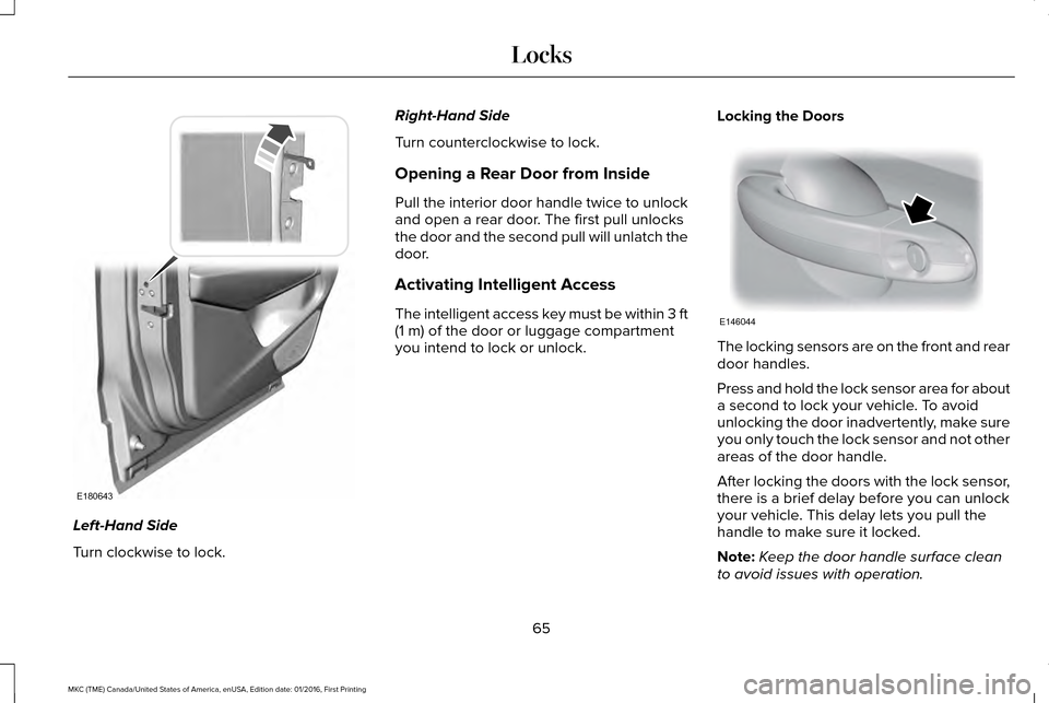
Left-Hand Side
Turn clockwise to lock. Right-Hand Side
Turn counterclockwise to lock.
Opening a Rear Door from Inside
Pull the interior door handle twice to unlock
and open a rear door. The first pull unlocks
the door and the second pull will unlatch the
door.
Activating Intelligent Access
The intelligent access key must be within 3 ft
(1 m) of the door or luggage compartment
you intend to lock or unlock. Locking the Doors The locking sensors are on the front and rear
door handles.
Press and hold the lock sensor area for about
a second to lock your vehicle. To avoid
unlocking the door inadvertently, make sure
you only touch the lock sensor and not other
areas of the door handle.
After locking the doors with the lock sensor,
there is a brief delay before you can unlock
your vehicle. This delay lets you pull the
handle to make sure it locked.
Note:
Keep the door handle surface clean
to avoid issues with operation.
65
MKC (TME) Canada/United States of America, enUSA, Edition date: 01/2016, First Printing LocksE180643 E146044
Page 294 of 538
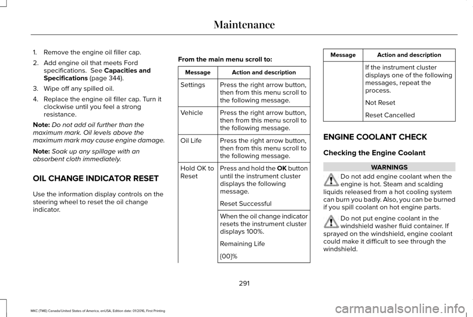
1. Remove the engine oil filler cap.
2. Add engine oil that meets Ford
specifications. See Capacities and
Specifications (page 344).
3. Wipe off any spilled oil.
4. Replace the engine oil filler cap. Turn it clockwise until you feel a strong
resistance.
Note: Do not add oil further than the
maximum mark. Oil levels above the
maximum mark may cause engine damage.
Note: Soak up any spillage with an
absorbent cloth immediately.
OIL CHANGE INDICATOR RESET
Use the information display controls on the
steering wheel to reset the oil change
indicator. From the main menu scroll to: Action and description
Message
Press the right arrow button,
then from this menu scroll to
the following message.
Settings
Press the right arrow button,
then from this menu scroll to
the following message.
Vehicle
Press the right arrow button,
then from this menu scroll to
the following message.
Oil Life
Press and hold the OK button
until the instrument cluster
displays the following
message.
Hold OK to
Reset
Reset Successful
When the oil change indicator
resets the instrument cluster
displays 100%.
Remaining Life
{00}% Action and description
Message
If the instrument cluster
displays one of the following
messages, repeat the
process.
Not Reset
Reset Cancelled
ENGINE COOLANT CHECK
Checking the Engine Coolant WARNINGS
Do not add engine coolant when the
engine is hot. Steam and scalding
liquids released from a hot cooling system
can burn you badly. Also, you can be burned
if you spill coolant on hot engine parts. Do not put engine coolant in the
windshield washer fluid container. If
sprayed on the windshield, engine coolant
could make it difficult to see through the
windshield.
291
MKC (TME) Canada/United States of America, enUSA, Edition date: 01/2016, First Printing Maintenance
Page 300 of 538
When a battery replacement is required, you
must use a recommended replacement
battery that matches the electrical
requirements of the vehicle.
Note:
If your vehicle has a battery cover,
after cleaning or replacing the battery, make
sure you reinstall it.
Note: See an authorized dealer for battery
access, testing, or replacement.
To make sure the battery management
system works correctly, do not connect an
electrical device ground connection directly
to the battery negative post. This can cause
inaccurate measurements of the battery
condition and potential incorrect system
operation.
Note: If you add electrical accessories or
components to the vehicle, it may adversely
affect battery performance and durability.
This may also affect the performance of
other electrical systems in the vehicle.
If you see any corrosion on the battery or
terminals, remove the cables from the
terminals and clean with a wire brush. You
can neutralize the acid with a solution of
baking soda and water. Because your vehicle
’s engine is
electronically-controlled by a computer,
some engine control settings are maintained
by power from the battery. Some engine
computer settings, like the idle trim and fuel
trim strategy, optimize the driveability and
performance of the engine. The clock and
radio station presets are also maintained in
memory by power from the low-voltage
battery. These settings are erased when a
technician disconnects and connects the
low-voltage battery.
To restore the settings, do the following:
Note: Until you switch the ignition to the on
position, you will receive a message in your
information display stating that your vehicle
is not in park.
1. Apply the parking brake.
2. Shift into park (P) or neutral (N).
3. Switch off all accessories.
4. Press the brake pedal and start your vehicle. 5. Run the engine until it reaches normal
operating temperature. While the engine
is warming up, complete the following:
Reset the clock. See Audio System
(page 362). Reset the power windows
bounce-back feature. See Windows and
Mirrors (page 93). Reset the radio station
presets. See Audio System (page 362).
6. Allow the engine to idle for at least one minute.
7. Drive the vehicle at least 10 mi (16 km) to
completely relearn the idle trim and fuel
trim strategy.
Note: If you do not allow the engine to
relearn the idle and fuel trim strategy, the
idle quality of your vehicle may be adversely
affected until the engine computer
eventually relearns the idle trim and fuel trim
strategy.
Note: Certain features may not operate if
the battery monitor system is not reset with
a scan tool following a jump start or battery
replacement. Normal electrical accessory
operation should resume after your vehicle
is left undisturbed for 8 hours.
297
MKC (TME) Canada/United States of America, enUSA, Edition date: 01/2016, First Printing Maintenance
Page 303 of 538
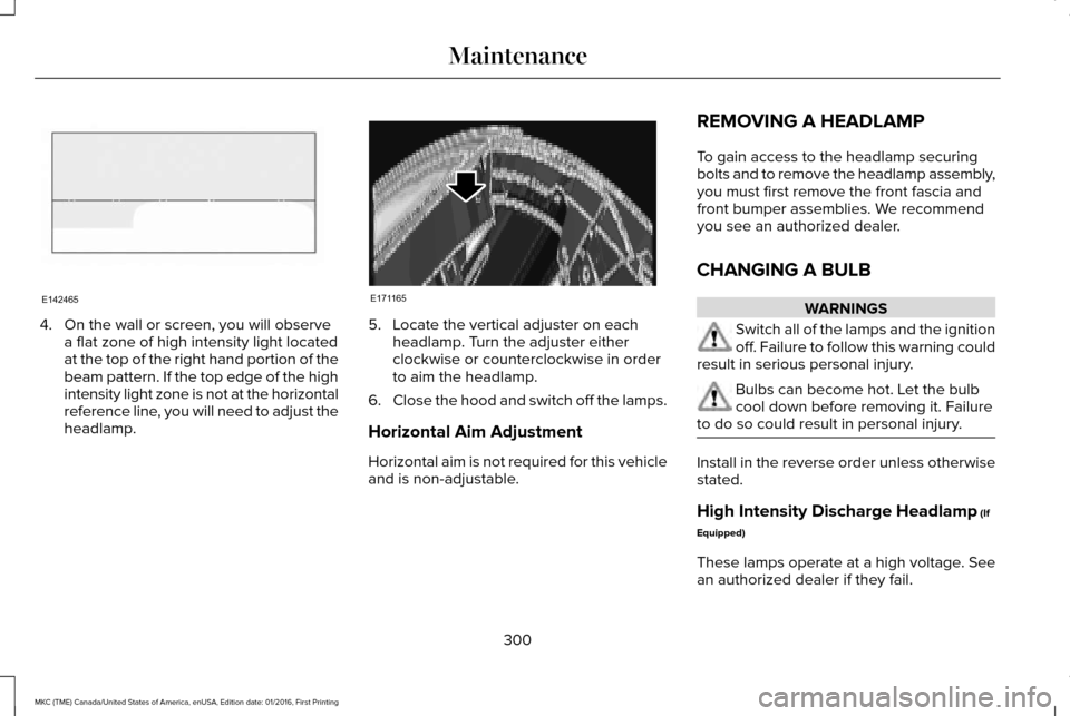
4. On the wall or screen, you will observe
a flat zone of high intensity light located
at the top of the right hand portion of the
beam pattern. If the top edge of the high
intensity light zone is not at the horizontal
reference line, you will need to adjust the
headlamp. 5. Locate the vertical adjuster on each
headlamp. Turn the adjuster either
clockwise or counterclockwise in order
to aim the headlamp.
6. Close the hood and switch off the lamps.
Horizontal Aim Adjustment
Horizontal aim is not required for this vehicle
and is non-adjustable. REMOVING A HEADLAMP
To gain access to the headlamp securing
bolts and to remove the headlamp assembly,
you must first remove the front fascia and
front bumper assemblies. We recommend
you see an authorized dealer.
CHANGING A BULB WARNINGS
Switch all of the lamps and the ignition
off. Failure to follow this warning could
result in serious personal injury. Bulbs can become hot. Let the bulb
cool down before removing it. Failure
to do so could result in personal injury. Install in the reverse order unless otherwise
stated.
High Intensity Discharge Headlamp (If
Equipped)
These lamps operate at a high voltage. See
an authorized dealer if they fail.
300
MKC (TME) Canada/United States of America, enUSA, Edition date: 01/2016, First Printing MaintenanceE142465 E171165
Page 304 of 538
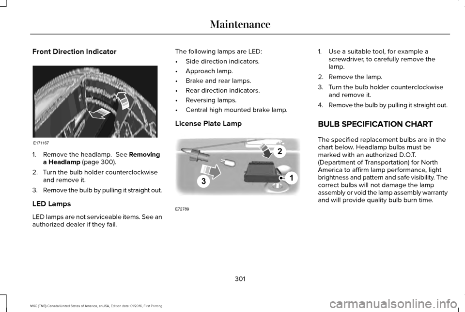
Front Direction Indicator
1. Remove the headlamp. See Removing
a Headlamp (page 300).
2. Turn the bulb holder counterclockwise and remove it.
3. Remove the bulb by pulling it straight out.
LED Lamps
LED lamps are not serviceable items. See an
authorized dealer if they fail. The following lamps are LED:
•
Side direction indicators.
• Approach lamp.
• Brake and rear lamps.
• Rear direction indicators.
• Reversing lamps.
• Central high mounted brake lamp.
License Plate Lamp 1. Use a suitable tool, for example a
screwdriver, to carefully remove the
lamp.
2. Remove the lamp.
3. Turn the bulb holder counterclockwise and remove it.
4. Remove the bulb by pulling it straight out.
BULB SPECIFICATION CHART
The specified replacement bulbs are in the
chart below. Headlamp bulbs must be
marked with an authorized D.O.T.
(Department of Transportation) for North
America to affirm lamp performance, light
brightness and pattern and safe visibility. The
correct bulbs will not damage the lamp
assembly or void the lamp assembly warranty
and will provide quality bulb burn time.
301
MKC (TME) Canada/United States of America, enUSA, Edition date: 01/2016, First Printing MaintenanceE171167 3
2
1
E72789
Page 341 of 538
•
Wet weather driving capability.
• All-wheel driving capability
When driving with the full-size dissimilar
spare wheel and tire assembly additional
caution should be given to:
• Towing a trailer.
• Driving vehicles equipped with a camper
body.
• Driving vehicles with a load on the cargo
rack.
Drive cautiously when using a full-size
dissimilar spare wheel and tire assembly and
seek service as soon as possible.
Tire Change Procedure WARNINGS
When one of the front wheels is off the
ground, the transmission alone will not
prevent your vehicle from moving or slipping
off the jack, even if the transmission is in park
(P) or neutral (N). WARNINGS
To help prevent your vehicle from
moving when you change a tire, be
sure to place the transmission in park (P) or
neutral (N), set the parking brake, and block
(in both directions) the wheel that is
diagonally opposite (other side and end of
your vehicle) to the tire being changed. Never get underneath a vehicle that is
supported only by a jack. If the vehicle
slips off the jack, you or someone else could
be seriously injured. Do not attempt to change a tire on the
side of the vehicle close to moving
traffic. Pull far enough off the road to avoid
the danger of being hit when operating the
jack or changing the wheel. Always use the jack provided as
original equipment with your vehicle.
If using a jack other than the one provided
as original equipment with your vehicle,
make sure the jack capacity is adequate for
the vehicle weight, including any vehicle
cargo or modifications. Note:
Passengers should not remain in your
vehicle when the vehicle is being jacked.
1. Park on a level surface, set the parking brake and activate the hazard flashers.
2. Place the transmission in park (P) and turn the engine off.
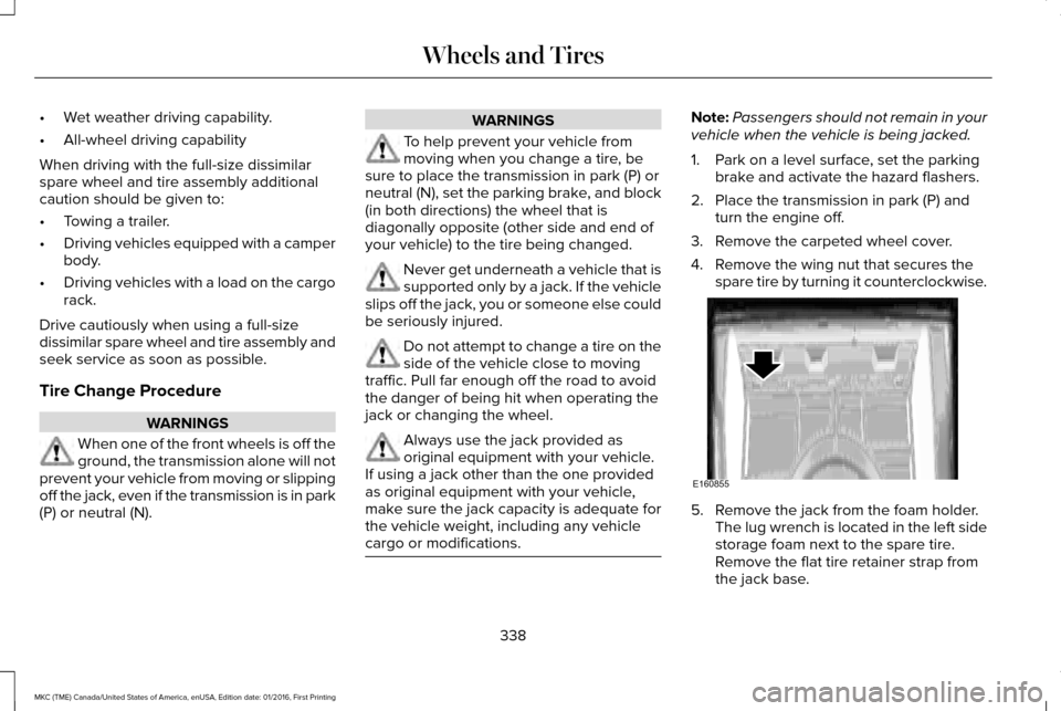
3. Remove the carpeted wheel cover.
4. Remove the wing nut that secures the spare tire by turning it counterclockwise. 5. Remove the jack from the foam holder.
The lug wrench is located in the left side
storage foam next to the spare tire.
Remove the flat tire retainer strap from
the jack base.
338
MKC (TME) Canada/United States of America, enUSA, Edition date: 01/2016, First Printing Wheels and TiresE160855
Page 342 of 538
6. Block the diagonally opposite wheel.
7.
Loosen each wheel lug nut one-half turn
counterclockwise, but do not remove
them until the wheel is raised off the
ground.
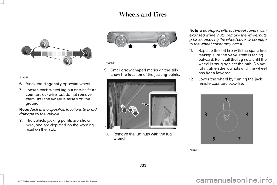
Note: Jack at the specified locations to avoid
damage to the vehicle.
8. The vehicle jacking points are shown here, and are depicted on the warning
label on the jack. 9. Small arrow-shaped marks on the sills
show the location of the jacking points. 10. Remove the lug nuts with the lug
wrench. Note:
If equipped with full wheel covers with
exposed wheel nuts, remove the wheel nuts
prior to removing the wheel cover or damage
to the wheel cover may occur.
11. Replace the flat tire with the spare tire,
making sure the valve stem is facing
outward. Reinstall the lug nuts until the
wheel is snug against the hub. Do not
fully tighten the lug nuts until the wheel
has been lowered.
12. Lower the wheel by turning the jack handle counterclockwise. 339
MKC (TME) Canada/United States of America, enUSA, Edition date: 01/2016, First Printing Wheels and TiresE142551 E145908 E162190 12
3
4
5
E75442
Page 371 of 538
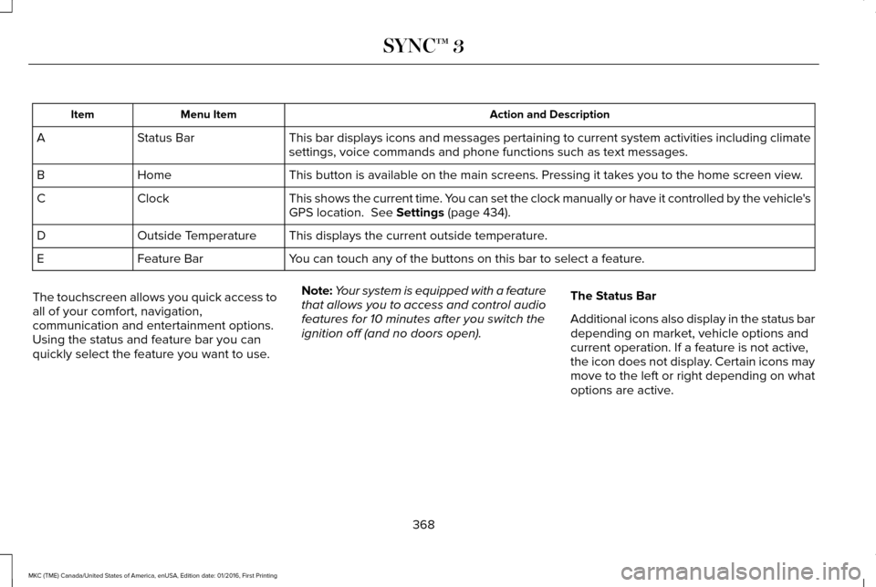
Action and Description
Menu Item
Item
This bar displays icons and messages pertaining to current system activi\
ties including climate
settings, voice commands and phone functions such as text messages.
Status Bar
A
This button is available on the main screens. Pressing it takes you to the home screen view.
Home
B
This shows the current time. You can set the clock manually or have it controlled by the vehicle's
GPS location. See Settings (page 434).
Clock
C
This displays the current outside temperature.
Outside Temperature
D
You can touch any of the buttons on this bar to select a feature.
Feature Bar
E
The touchscreen allows you quick access to
all of your comfort, navigation,
communication and entertainment options.
Using the status and feature bar you can
quickly select the feature you want to use. Note:
Your system is equipped with a feature
that allows you to access and control audio
features for 10 minutes after you switch the
ignition off (and no doors open). The Status Bar
Additional icons also display in the status bar
depending on market, vehicle options and
current operation. If a feature is not active,
the icon does not display. Certain icons may
move to the left or right depending on what
options are active.
368
MKC (TME) Canada/United States of America, enUSA, Edition date: 01/2016, First Printing SYNC™ 3
Page 414 of 538
Note: This feature only functions when you switch the engine on.
Touch this icon to switch the heated steering wheel on and off. It takes about 5 minutes to warm the steering wheel to 74°F in
temperatures as low as -4°F. The wheel maintains an approximate temperature of 90°F and operates independently from the heated\
seats and other climate-control functions. The heating element is in bet\
ween the leather covering and foam core to help provide
maximum heat without adversely affecting the feel of the steering wheel.\
Note:
The heated steering wheel may remain on after remote starting the vehic\
le, based on your remote start settings. The heated
steering wheel may also turn on when you start your vehicle, if it was on when you switched your vehicle off.
Note:
For steering wheels with wood trim, the heating feature will not heat t\
he wheel between the 10 and 2 o'clock positions.
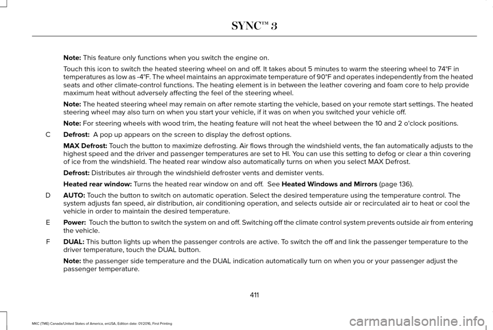
Defrost:
A pop up appears on the screen to display the defrost options.
C
MAX Defrost: Touch the button to maximize defrosting. Air flows through the windshield\
vents, the fan automatically adjusts to the
highest speed and the driver and passenger temperatures are set to HI. Y\
ou can use this setting to defog or clear a thin covering
of ice from the windshield. The heated rear window also automatically tu\
rns on when you select MAX Defrost.
Defrost:
Distributes air through the windshield defroster vents and demister vent\
s.
Heated rear window:
Turns the heated rear window on and off. See Heated Windows and Mirrors (page 136).
AUTO:
Touch the button to switch on automatic operation. Select the desired tem\
perature using the temperature control. The
system adjusts fan speed, air distribution, air conditioning operation, \
and selects outside air or recirculated air to heat or cool the
vehicle in order to maintain the desired temperature.
D
Power:
Touch the button to switch the system on and off. Switching off the climate control system prevents outside air from enteri\
ng
the vehicle.
E
DUAL:
This button lights up when the passenger controls are active. To switch the off and link the passenger temperature to the
driver temperature, touch the DUAL button.
F
Note:
the passenger side temperature and the DUAL indication automatically turn on when you or your passenger adjust th\
e
passenger temperature.
411
MKC (TME) Canada/United States of America, enUSA, Edition date: 01/2016, First Printing SYNC™ 3