headlamp LINCOLN MKS 2015 User Guide
[x] Cancel search | Manufacturer: LINCOLN, Model Year: 2015, Model line: MKS, Model: LINCOLN MKS 2015Pages: 424, PDF Size: 3.96 MB
Page 90 of 424
Keyless Warning Alert (If Equipped)
Sounds the horn twice when you exit your
vehicle with the intelligent access key, after
the last door is closed and your keyless
vehicle is in RUN, indicating your vehicle is
still on.
Headlamps On Warning Chime
Sounds when you remove the key from the
ignition and open the driver's door and you
have left the headlamps or parking lamps on.
Parking Brake On Warning Chime
Sounds when you have left the parking brake
on and drive your vehicle. If the warning
chime remains on after you have released
the parking brake, have the system checked
by an authorized dealer immediately.
87
MKS (), enUSA Instrument Cluster
Page 130 of 424
On: All electrical circuits are operational and
the warning lamps and indicators illuminate.
• Without applying the brake pedal, press
and release the button once.
Start:
Starts the engine.
• Press the brake pedal, and then press the
button for any length of time. An indicator
light on the button illuminates when then
ignition is on and when the engine starts.
STARTING A GASOLINE ENGINE
When you start the engine, the idle speed
increases, this helps to warm up the engine.
If the engine idle speed does not slow down
automatically, have your vehicle checked by
an authorized dealer. Note:
You can crank the engine for a total of
60 seconds (without the engine starting)
before the starting system temporarily
disables. The 60 seconds does not have to be
all at once. For example, if you crank the
engine three times for 20 seconds each time,
without the engine starting, you reached the
60-second time limit. A message appears in
the information display alerting you that you
exceeded the cranking time. You cannot
attempt to start the engine for at least 15
minutes. After 15 minutes, you are limited to a
15-second engine cranking time. You need to
wait 60 minutes before you can crank the
engine for 60 seconds again.
Before starting the engine, check the
following:
• Make sure all occupants have fastened
their safety belts.
• Make sure the headlamps and electrical
accessories are off.
• Make sure the parking brake is on.
• Put the transmission in park (P).
Note: Do not touch the accelerator pedal.
1. Fully press the brake pedal.
2. Press the button. The system does not function if:
•
The key frequencies are jammed.
• The key battery has no charge.
If you are unable to start the engine, do the
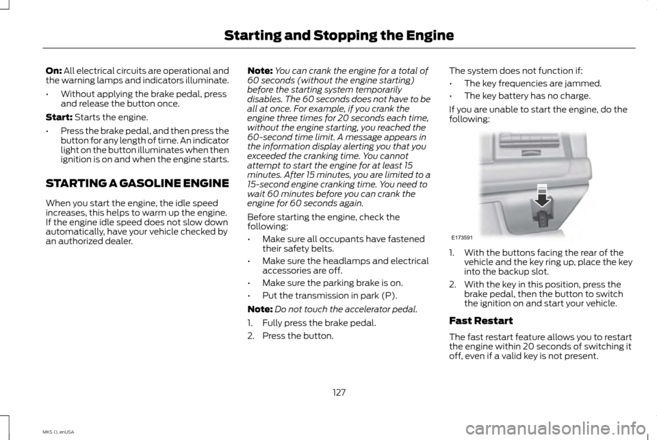
following: 1. With the buttons facing the rear of the
vehicle and the key ring up, place the key
into the backup slot.
2. With the key in this position, press the brake pedal, then the button to switch
the ignition on and start your vehicle.
Fast Restart
The fast restart feature allows you to restart
the engine within 20 seconds of switching it
off, even if a valid key is not present.
127
MKS (), enUSA Starting and Stopping the EngineE173591
Page 177 of 424
•
Low
• Medium
• High
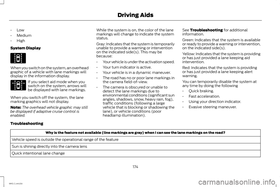
System Display When you switch on the system, an overhead
graphic of a vehicle with lane markings will
display in the information display.
If you select aid mode when you
switch on the system, arrows will
be displayed with lane markings.
When you switch off the system, the lane
marking graphics will not display.
Note: The overhead vehicle graphic may still
be displayed if adaptive cruise control is
enabled. While the system is on, the color of the lane
markings will change to indicate the system
status.
Gray: Indicates that the system is temporarily
unable to provide a warning or intervention
on the indicated side(s). This may be
because:
•
Your vehicle is under the activation speed.
• Your turn indicator is active.
• Your vehicle is in a dynamic maneuver.
• The road has no or poor lane markings in
the camera field-of-view.
• The camera is obscured or unable to
detect the lane markings due to
environmental conditions (significant sun
angles, shadows, snow, heavy rain, fog),
traffic conditions (following a large
vehicle that is blocking or shadowing the
lane), or vehicle conditions (poor
headlamp illumination). See Troubleshooting for additional
information.
Green: Indicates that the system is available
or ready to provide a warning or intervention,
on the indicated side(s).
Yellow: Indicates that the system is providing
or has just provided a lane keeping aid
intervention.
Red: Indicates that the system is providing
or has just provided a lane keeping alert
warning.
You can temporarily disable the system at
any time by doing the following
• Quick braking.
• Fast acceleration.
• Using your direction indicator.
• Evasive steering maneuver.
Troubleshooting Why is the feature not available (line markings are gray) when I can see the lane markings on the road?
Vehicle speed is outside the operational range of the feature
Sun is shining directly into the camera lens
Quick intentional lane change
174
MKS (), enUSA Driving AidsE144813 E173234
Page 187 of 424
Action
Cause
Clean the grille surface in front of the radar or remove the objectcausing the obstruction
The surface of the radar in the grille is dirty or obstructed in some way
Wait a short time. It may take several minutes for the radar to detectthat it is no longer obstructed
The surface of the radar in the grille is clean but the message remains
in the display
The collision warning system is temporarily disabled. Collision warning
should automatically reactivate a short time after the weather condi-tions improve
Heavy rain, spray, snow, or fog is interfering with the radar signals
The collision warning system is temporarily disabled. Collision warning
should automatically reactivate a short time after the weather condi-tions improve
Swirling water, or snow or ice on the surface of the road may interfere
with the radar signals
System Limitations WARNING
The collision warning system
’s brake
support can only help reduce the speed
at which a collision occurs if the driver
applies the vehicle ’s brakes. The brake pedal
must be pressed just like any typical braking
situation. Due to the nature of radar technology, there
may be certain instances where vehicles do
not provide a collision warning. These include: •
Stationary vehicles or vehicles moving
below 6 mph (10 km/h).
• Pedestrians or objects in the roadway.
• Oncoming vehicles in the same lane.
• Severe weather conditions (see blocked
sensor section).
• Debris build-up on the grille near the
headlamps (see blocked sensor section).
• Small distance to vehicle ahead.
• Steering wheel and pedal movements
are large (very active driving style). If the front end of the vehicle is hit or
damaged, the radar sensing zone may be
altered causing missed or false collision
warnings. See your authorized dealer to have
your collision warning radar checked for
proper coverage and operation.
184
MKS (), enUSA Driving Aids
Page 225 of 424
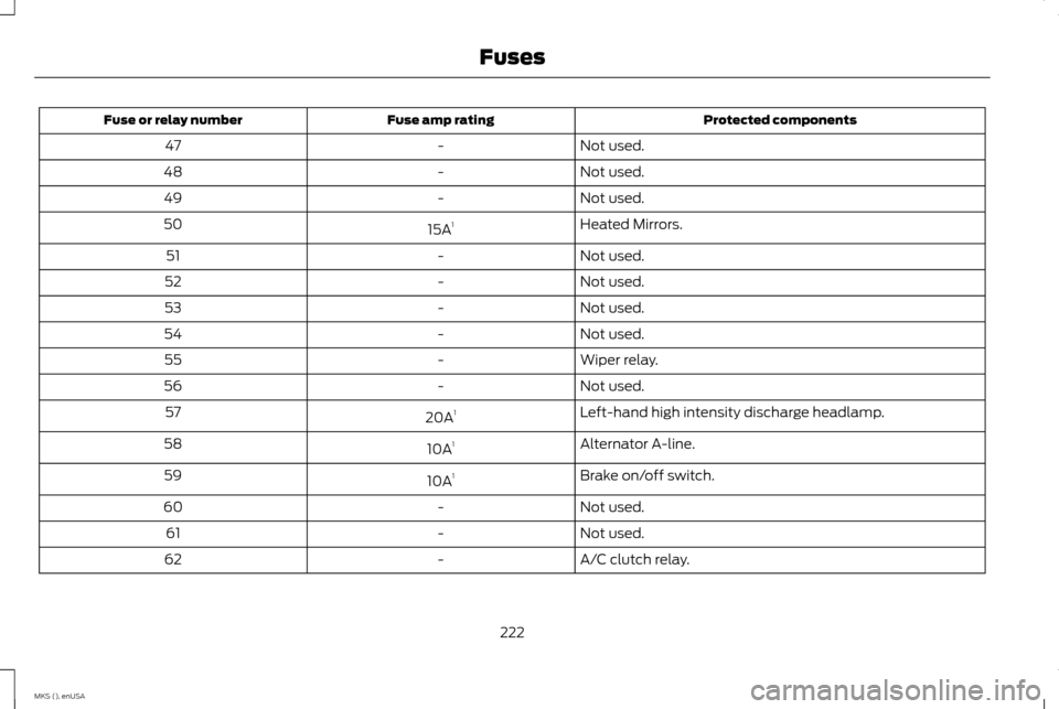
Protected components
Fuse amp rating
Fuse or relay number
Not used.
-
47
Not used.
-
48
Not used.
-
49
Heated Mirrors.
15A 1
50
Not used.
-
51
Not used.
-
52
Not used.
-
53
Not used.
-
54
Wiper relay.
-
55
Not used.
-
56
Left-hand high intensity discharge headlamp.
20A 1
57
Alternator A-line.
10A 1
58
Brake on/off switch.
10A 1
59
Not used.
-
60
Not used.
-
61
A/C clutch relay.
-
62
222
MKS (), enUSA Fuses
Page 227 of 424
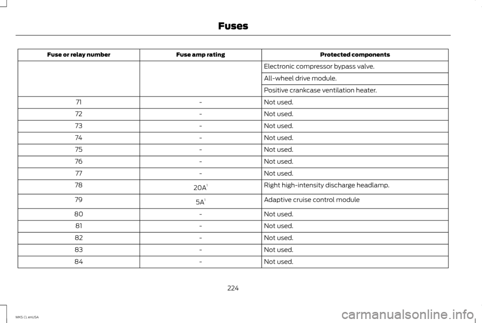
Protected components
Fuse amp rating
Fuse or relay number
Electronic compressor bypass valve.
All-wheel drive module.
Positive crankcase ventilation heater.
Not used.
-
71
Not used.
-
72
Not used.
-
73
Not used.
-
74
Not used.
-
75
Not used.
-
76
Not used.
-
77
Right high-intensity discharge headlamp.
20A 1
78
Adaptive cruise control module
5A 1
79
Not used.
-
80
Not used.
-
81
Not used.
-
82
Not used.
-
83
Not used.
-
84
224
MKS (), enUSA Fuses
Page 228 of 424
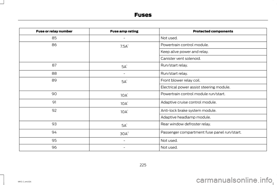
Protected components
Fuse amp rating
Fuse or relay number
Not used.
-
85
Powertrain control module.
7.5A 1
86
Keep alive power and relay.
Canister vent solenoid.
Run/start relay.
5A 1
87
Run/start relay.
-
88
Front blower relay coil.
5A 1
89
Electrical power assist steering module.
Powertrain control module run/start.
10A 1
90
Adaptive cruise control module.
10A 1
91
Anti-lock brake system module.
10A 1
92
Adaptive headlamp module.
Rear window defroster relay.
5A 1
93
Passenger compartment fuse panel run/start.
30A 2
94
Not used.
-
95
Not used.
-
96
225
MKS (), enUSA Fuses
Page 254 of 424
2. Press the locking buttons together.
3. Rotate and remove the wiper blade.
4. Install in the reverse order.
Note:
Make sure that the wiper blade locks
into place. Lower the wiper arm and blade
back to the windshield. The wiper arms will
automatically return to their normal position
when the ignition is turned on.
Replace wiper blades at least once per year
for optimum performance.
Poor wiper quality can be improved by
cleaning the wiper blades and the windshield. ADJUSTING THE HEADLAMPS
Vertical Aim Adjustment
The headlamps on your vehicle are properly
aimed at the assembly plant. If your vehicle
has been in an accident, have the alignment
of your headlamps checked by your
authorized dealer.
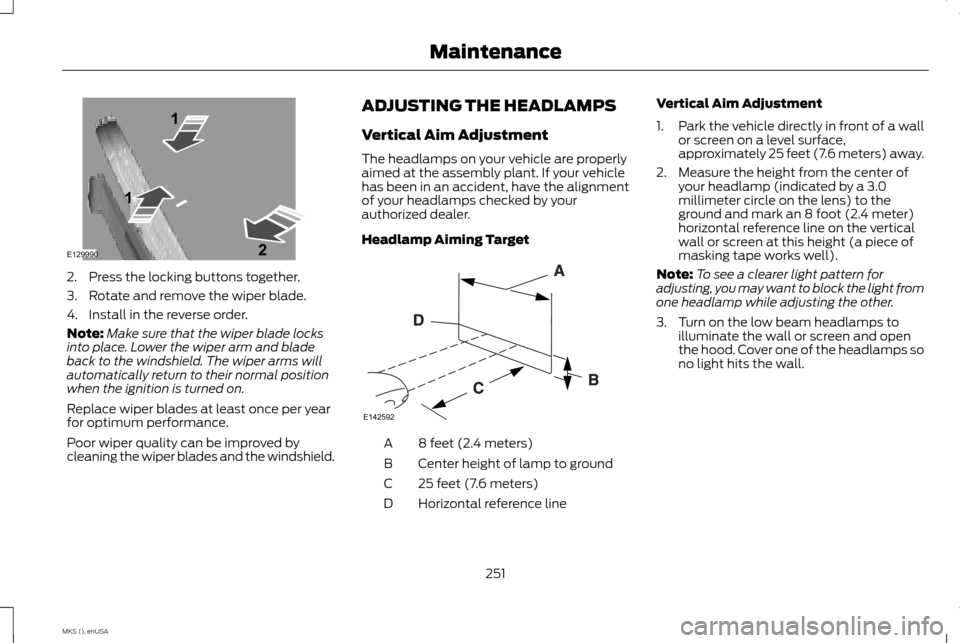
Headlamp Aiming Target
8 feet (2.4 meters)
A
Center height of lamp to ground
B
25 feet (7.6 meters)
C
Horizontal reference line
D Vertical Aim Adjustment
1.
Park the vehicle directly in front of a wall
or screen on a level surface,
approximately 25 feet (7.6 meters) away.
2. Measure the height from the center of your headlamp (indicated by a 3.0
millimeter circle on the lens) to the
ground and mark an 8 foot (2.4 meter)
horizontal reference line on the vertical
wall or screen at this height (a piece of
masking tape works well).
Note: To see a clearer light pattern for
adjusting, you may want to block the light from
one headlamp while adjusting the other.
3. Turn on the low beam headlamps to illuminate the wall or screen and open
the hood. Cover one of the headlamps so
no light hits the wall.
251
MKS (), enUSA MaintenanceE129990
1
1 2 E142592
Page 255 of 424
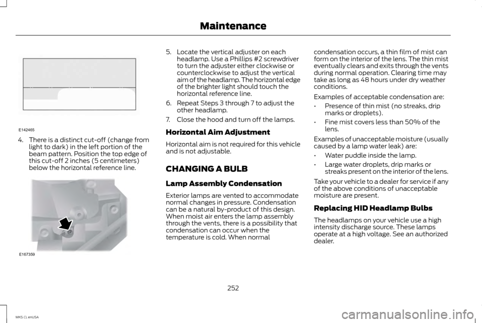
4. There is a distinct cut-off (change from
light to dark) in the left portion of the
beam pattern. Position the top edge of
this cut-off 2 inches (5 centimeters)
below the horizontal reference line. 5. Locate the vertical adjuster on each
headlamp. Use a Phillips #2 screwdriver
to turn the adjuster either clockwise or
counterclockwise to adjust the vertical
aim of the headlamp. The horizontal edge
of the brighter light should touch the
horizontal reference line.
6. Repeat Steps 3 through 7 to adjust the other headlamp.
7. Close the hood and turn off the lamps.
Horizontal Aim Adjustment
Horizontal aim is not required for this vehicle
and is not adjustable.
CHANGING A BULB
Lamp Assembly Condensation
Exterior lamps are vented to accommodate
normal changes in pressure. Condensation
can be a natural by-product of this design.
When moist air enters the lamp assembly
through the vents, there is a possibility that
condensation can occur when the
temperature is cold. When normal condensation occurs, a thin film of mist can
form on the interior of the lens. The thin mist
eventually clears and exits through the vents
during normal operation. Clearing time may
take as long as 48 hours under dry weather
conditions.
Examples of acceptable condensation are:
•
Presence of thin mist (no streaks, drip
marks or droplets).
• Fine mist covers less than 50% of the
lens.
Examples of unacceptable moisture (usually
caused by a lamp water leak) are:
• Water puddle inside the lamp.
• Large water droplets, drip marks or
streaks present on the interior of the lens.
Take your vehicle to a dealer for service if any
of the above conditions of unacceptable
moisture are present.
Replacing HID Headlamp Bulbs
The headlamps on your vehicle use a high
intensity discharge source. These lamps
operate at a high voltage. See an authorized
dealer.
252
MKS (), enUSA MaintenanceE142465 E167359
Page 256 of 424
Replacing Front Parking, Direction
Indicator and Sidemarker Bulbs
These lamps are designed with LED light
sources. See an authorized dealer.
Replacing Fog Lamp Bulbs (If
Equipped)
1. Make sure the headlamps are off.
2.
Disconnect the electrical connector from
the fog lamp bulb.
3. Turn the bulb counterclockwise and remove it from the fog lamp.
4. Install the new bulb in reverse order. Replacing Brake, Tail, Rear Direction
Indicator and Reverse Lamp Bulbs
These lamps are designed with LED light
sources. See an authorized dealer.
Replacing High-mount Brake Lamp
Bulbs
These lamps are designed with LED light
sources. See an authorized dealer.
Replacing the License Plate Lamp
Bulb
1.
Make sure the lighting control switch is in
the off position. 2. Remove the screws and lens from the
license plate lamp assembly. 3. Carefully pull the bulb straight out from
the lamp assembly.
Install new bulb in reverse order.
BULB SPECIFICATION CHART
The specified replacement bulbs are in the
chart below. Headlamp bulbs must be
marked with an authorized D.O.T.
(Department of Transportation) for North
America to affirm lamp performance, light
brightness and pattern and safe visibility. The
correct bulbs will not damage the lamp
assembly or void the lamp assembly
warranty and will provide quality bulb burn
time.
253
MKS (), enUSA MaintenanceE163826 E178598 E178599