fuse LINCOLN MKT 2015 Owners Manual
[x] Cancel search | Manufacturer: LINCOLN, Model Year: 2015, Model line: MKT, Model: LINCOLN MKT 2015Pages: 500, PDF Size: 4.94 MB
Page 7 of 500
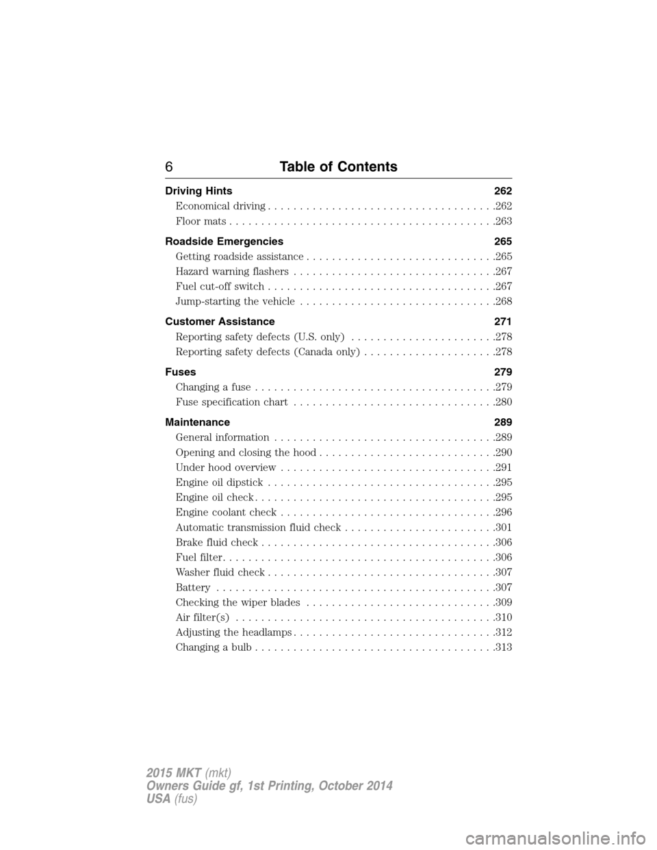
Driving Hints 262
Economical driving....................................262
Floormats..........................................263
Roadside Emergencies 265
Getting roadside assistance..............................265
Hazard warning flashers................................267
Fuel cut-off switch....................................267
Jump-starting the vehicle...............................268
Customer Assistance 271
Reporting safety defects (U.S. only).......................278
Reporting safety defects (Canada only).....................278
Fuses 279
Changing a fuse......................................279
Fuse specification chart................................280
Maintenance 289
General information...................................289
Opening and closing the hood............................290
Under hood overview..................................291
Engine oil dipstick....................................295
Engine oil check......................................295
Engine coolant check..................................296
Automatic transmission fluid check........................301
Brake fluid check.....................................306
Fuel filter...........................................306
Washer fluid check....................................307
Battery ............................................307
Checking the wiper blades..............................309
Air filter(s).........................................310
Adjusting the headlamps................................312
Changing a bulb......................................313
6Table of Contents
2015 MKT(mkt)
Owners Guide gf, 1st Printing, October 2014
USA(fus)
Page 11 of 500
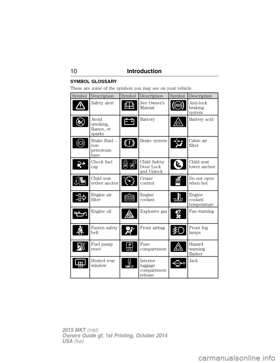
SYMBOL GLOSSARY
These are some of the symbols you may see on your vehicle.
Symbol Description Symbol Description Symbol Description
Safety alertSee Owner’s
ManualAnti-lock
braking
system
Avoid
smoking,
flames, or
sparksBatteryBattery acid
Brake fluid –
non
petroleum
baseBrake systemCabin air
filter
Check fuel
capChild Safety
Door Lock
and UnlockChild seat
lower anchor
Child seat
tether anchorCruise
controlDo not open
when hot
Engine air
filterEngine
coolantEngine
coolant
temperature
Engine oilExplosive gasFan warning
Fasten safety
beltFront airbagFront fog
lamps
Fuel pump
resetFuse
compartmentHazard
warning
flasher
Heated rear
windowInterior
luggage
compartment
releaseJack
10Introduction
2015 MKT(mkt)
Owners Guide gf, 1st Printing, October 2014
USA(fus)
Page 51 of 500
PRINCIPLES OF OPERATION
WARNING:Airbags do not inflate slowly or gently, and the risk
of injury from a deploying airbag is the greatest close to the trim
covering the airbag module.
WARNING:All occupants of your vehicle, including the driver,
should always properly wear their safety belts, even when an
airbag supplemental restraint system is provided. Failure to properly
wear your safety belt could seriously increase the risk of injury or
death.
WARNING:Airbags can kill or injure a child in a child seat.
Always transport children 12 years old and under in the back
seat and always properly use appropriate child restraints.
WARNING:Never place your arm over the airbag module, as a
deploying airbag can result in serious arm fractures or other
injuries.
WARNING:Airbags can kill or injure a child in a child seat.
Never place a rear-facing child seat in front of an active airbag. If
you must use a forward-facing child seat in the front seat, move the
seat upon which the child seat is installed all the way back.
WARNING:Do not attempt to service, repair, or modify the
airbag supplemental restraint systems or its fuses as you could be
seriously injured or killed. Contact your authorized dealer as soon as
possible.
WARNING:Several airbag system components get hot after
inflation. Do not touch them after inflation as this may result in
serious injury.
50Supplementary Restraints System
2015 MKT(mkt)
Owners Guide gf, 1st Printing, October 2014
USA(fus)
Page 59 of 500
WARNING:Do not attempt to service, repair, or modify the
airbag, its fuses or the seat cover on a seat containing an airbag,
as you could be seriously injured or killed. Contact your authorized
dealer as soon as possible.
WARNING:If the side airbag has deployed, the airbag will not
function again. The side airbag system (including the seat) must
be inspected and serviced by an authorized dealer. If the airbag is not
replaced, the unrepaired area will increase the risk of injury in a crash.
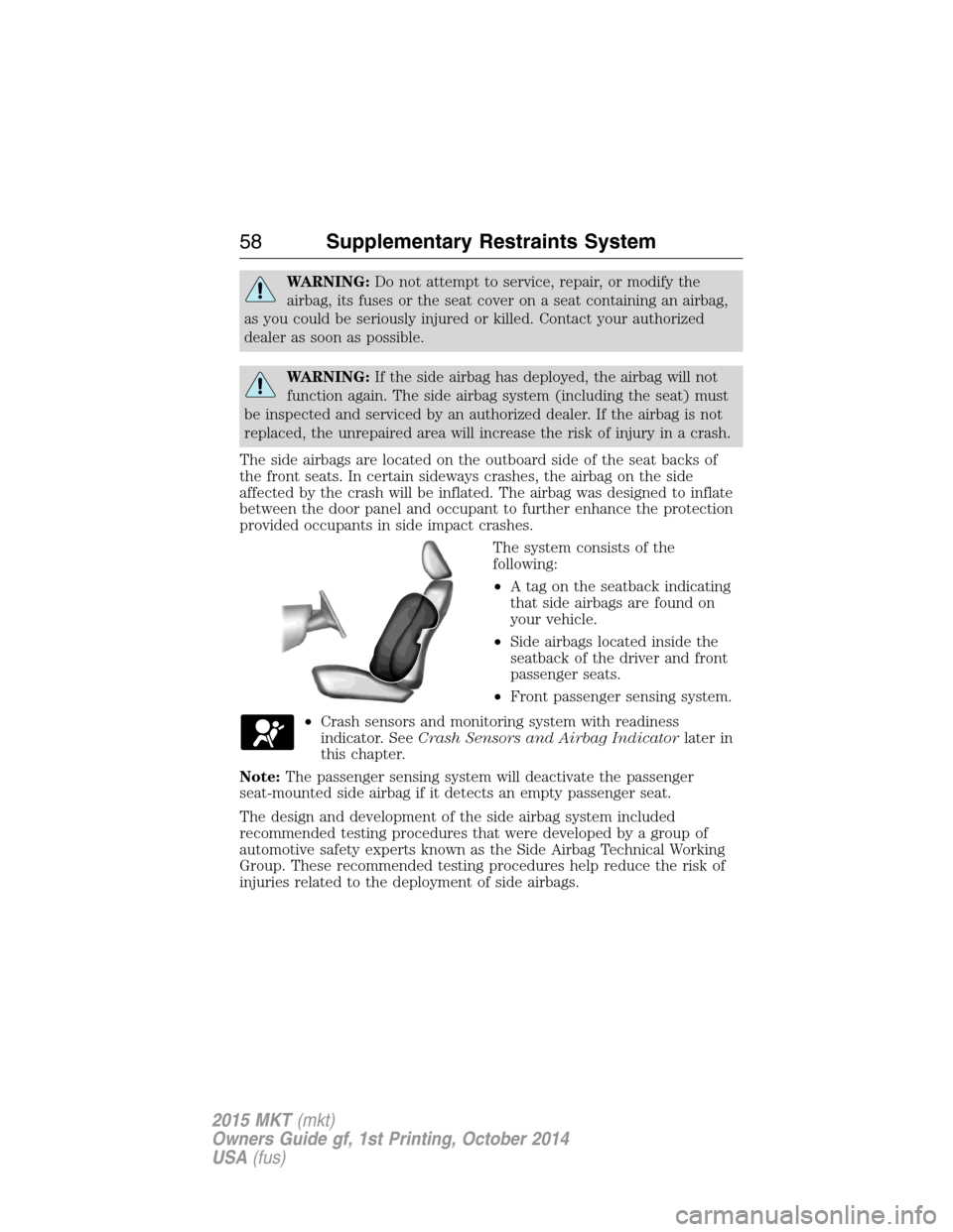
The side airbags are located on the outboard side of the seat backs of
the front seats. In certain sideways crashes, the airbag on the side
affected by the crash will be inflated. The airbag was designed to inflate
between the door panel and occupant to further enhance the protection
provided occupants in side impact crashes.
The system consists of the
following:
•A tag on the seatback indicating
that side airbags are found on
your vehicle.
•Side airbags located inside the
seatback of the driver and front
passenger seats.
•Front passenger sensing system.
•Crash sensors and monitoring system with readiness
indicator. SeeCrash Sensors and Airbag Indicatorlater in
this chapter.
Note:The passenger sensing system will deactivate the passenger
seat-mounted side airbag if it detects an empty passenger seat.
The design and development of the side airbag system included
recommended testing procedures that were developed by a group of
automotive safety experts known as the Side Airbag Technical Working
Group. These recommended testing procedures help reduce the risk of
injuries related to the deployment of side airbags.
58Supplementary Restraints System
2015 MKT(mkt)
Owners Guide gf, 1st Printing, October 2014
USA(fus)
Page 60 of 500
SAFETY CANOPY™ CURTAIN AIRBAGS
WARNING:Do not place objects or mount equipment on or near
the headliner at the siderail that may come into contact with a
deploying curtain airbag. Failure to follow these instructions may
increase the risk of personal injury in the event of a crash.
WARNING:Do not lean your head on the door. The curtain
airbag could injure you as it deploys from the headliner.
WARNING:Do not attempt to service, repair, or modify the
curtain airbags, its fuses, the A, B, C or D pillar trim, or the
headliner on a vehicle containing curtain airbags, as you could be
seriously injured or killed. Contact your authorized dealer as soon as
possible.
WARNING:All occupants of your vehicle including the driver
should always wear their safety belts even when an airbag
supplemental restraint system and curtain airbag is provided. Failure to
properly wear your safety belt could seriously increase the risk of injury
or death.
WARNING:To reduce risk of injury, do not obstruct or place
objects in the deployment path of the curtain airbag.
WARNING:If the curtain airbags have deployed, the curtain
airbags will not function again. The curtain airbags (including the
A, B, C or D pillar trim and headliner) must be inspected and serviced
by an authorized dealer. If the curtain airbag is not replaced, the
unrepaired area will increase the risk of injury in a crash.
Supplementary Restraints System59
2015 MKT(mkt)
Owners Guide gf, 1st Printing, October 2014
USA(fus)
Page 166 of 500
AUXILIARY POWER POINTS
WARNING:Do not plug optional electrical accessories into the
cigarette lighter socket (if equipped). Improper use of the lighter
can cause damage not covered by your warranty, and can result in fire
or serious injury.
Note:If used when the engine is not running, the battery will discharge.
There may be insufficient power to restart your engine.
Note:Do not insert objects other than an accessory plug into the power
point. This will damage the outlet and blow the fuse.
Note:Do not hang any type of accessory or accessory bracket from the
plug.
Note:Do not use the power point over the vehicle capacity of 12 volt
DC 180 watts or a fuse may blow.
Note:Do not use the power point for operating a cigarette lighter
element.
Note:Improper use of the power outlet can cause damage not covered
by your warranty.
Note:Always keep the power point caps closed when not in use.
Run the engine for full capacity use of the power point. To prevent the
battery from being discharged:
•Do not use the power point longer than necessary when the engine is
not running.
•Do not leave devices plugged in overnight or when the vehicle is
parked for extended periods.
Locations
Power points may be found:
•near the floor in the front console bin on the driver’s side
•in the center console storage compartment
•on the rear of the center console (inside the second row center
console on vehicle equipped with that feature)
•in the rear cargo area on the left rear trim panel.
Auxiliary Power Points165
2015 MKT(mkt)
Owners Guide gf, 1st Printing, October 2014
USA(fus)
Page 191 of 500
Brake-shift interlock
WARNING:Do not drive your vehicle until you verify that the
brakelamps are working.
WARNING:When doing this procedure, you will be taking the
vehicle out of park which means the vehicle can roll freely. To
avoid unwanted vehicle movement, always fully set the parking brake
prior to doing this procedure. Use wheel chocks if appropriate.
WARNING:If the parking brake is fully released, but the brake
warning lamp remains illuminated, the brakes may not be
working properly. See your authorized dealer.
Note:See your authorized dealer as soon as possible if this procedure is
used.
This vehicle is equipped with a brake-shift interlock feature that prevents
the gearshift lever from being moved from P (Park) when the ignition is
on unless the brake pedal is pressed.
If you cannot move the gearshift lever out of P (Park) with the ignition
on and the brake pedal pressed, it is possible that a fuse has blown or
the vehicle’s brake lamps are not operating properly. Refer to theFuses
chapter.
If the fuse is not blown and the brake lamps are working properly, the
following procedure will allow you to move the gearshift lever from P
(Park):
1. Apply the parking brake, turn the ignition off, and remove the key.
190Transmission
2015 MKT(mkt)
Owners Guide gf, 1st Printing, October 2014
USA(fus)
Page 253 of 500
TOWING A TRAILER
WARNING:Do not exceed the GVWR or the GAWR specified on
the certification label.
WARNING:Towing trailers beyond the maximum recommended
gross trailer weight exceeds the limit of your vehicle and could
result in engine damage, transmission damage, structural damage, loss
of vehicle control, vehicle rollover and personal injury.
Note:For information on electrical items such as fuses or relays, see the
Fuseschapter.
The load capacity of your vehicle is designated by weight not volume.
You may not necessarily be able to use all available space when loading
your vehicle or trailer.
Towing a trailer places extra load on the engine, transmission, axle,
brakes, tires, and suspension. Inspect these components before, during
and after towing.
Load Placement
To help minimize how trailer movement affects your vehicle when
driving:
•Load the heaviest items closest to the trailer floor.
•Load the heaviest items centered between the left and right side
trailer tires.
•Load the heaviest items above the trailer axles or just slightly forward
toward the trailer tongue. Do not allow the final trailer tongue weight
to go above or below 10–15% of the loaded trailer weight.
•Select a tow bar with the correct rise or drop. When both the loaded
vehicle and trailer are connected, the trailer frame should be level, or
slightly angled down toward your vehicle, when viewed from the side.
When driving with a trailer or payload, a slight takeoff vibration or
shudder may be present due to the increased payload weight. You can
find more information about proper trailer loading and setting your
vehicle up for towing underLoad limitin theLoad Carryingchapter.
You can also find information in theRV and Trailer Towing Guide
available at your authorized dealer, or online at
http://www.fleet.ford.com/towing-guides.
252Towing
2015 MKT(mkt)
Owners Guide gf, 1st Printing, October 2014
USA(fus)
Page 280 of 500
CHANGING A FUSE
Fuses
WARNING:Always replace a fuse with one that has the
specified amperage rating. Using a fuse with a higher amperage
rating can cause severe wire damage and could start a fire.
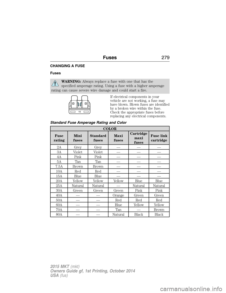
If electrical components in your
vehicle are not working, a fuse may
have blown. Blown fuses are identified
by a broken wire within the fuse.
Check the appropriate fuses before
replacing any electrical components.
Standard Fuse Amperage Rating and Color
COLOR
Fuse
ratingMini
fusesStandard
fusesMaxi
fusesCartridge
maxi
fusesFuse link
cartridge
2A Grey Grey — — —
3A Violet Violet — — —
4A Pink Pink — — —
5A Tan Tan — — —
7.5A Brown Brown — — —
10A Red Red — — —
15A Blue Blue — — —
20A Yellow Yellow Yellow Blue Blue
25A Natural Natural — Natural Natural
30A Green Green Green Pink Pink
40A — — Orange Green Green
50A — — Red Red Red
60A — — Blue Yellow Yellow
70A — — Tan — Brown
80A — — Natural Black Black
15
Fuses279
2015 MKT(mkt)
Owners Guide gf, 1st Printing, October 2014
USA(fus)
Page 281 of 500
FUSE SPECIFICATION CHART
Power Distribution Box
WARNING:Always disconnect the battery before servicing high
current fuses.
WARNING:To reduce risk of electrical shock, always replace the
cover to the power distribution box before reconnecting the
battery or refilling fluid reservoirs.
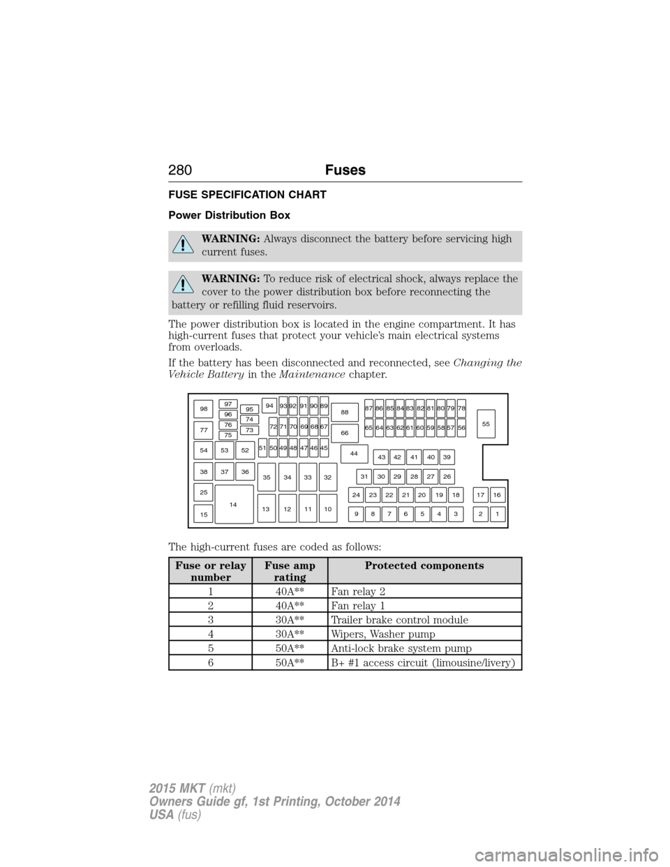
The power distribution box is located in the engine compartment. It has
high-current fuses that protect your vehicle’s main electrical systems
from overloads.
If the battery has been disconnected and reconnected, seeChanging the
Vehicle Batteryin theMaintenancechapter.
The high-current fuses are coded as follows:
Fuse or relay
numberFuse amp
ratingProtected components
1 40A** Fan relay 2
2 40A** Fan relay 1
3 30A** Trailer brake control module
4 30A** Wipers, Washer pump
5 50A** Anti-lock brake system pump
6 50A** B+ #1 access circuit (limousine/livery)
97
98
77969594
93 92 91 90 89
88
66
4478
56
39
26
18 1617
312 4 5 6 7 8 919 20 21 22 23 2427 28 29 30 3140 41 42 4355
57 58 59 60 61 62 63 64 6579 80 81 82 83 84 85 86 87
67
45
32
10 11 12 1333 34 3546 47 48 49 50 5168 69 70 71 72 74
73 76
75
53
37 36 54
38
25
151452
280Fuses
2015 MKT(mkt)
Owners Guide gf, 1st Printing, October 2014
USA(fus)