clock LINCOLN MKT 2017 Owners Manual
[x] Cancel search | Manufacturer: LINCOLN, Model Year: 2017, Model line: MKT, Model: LINCOLN MKT 2017Pages: 558, PDF Size: 4.59 MB
Page 40 of 558

The childproof locks are located on the rear
edge of each rear door and must be set
separately for each door.
Left-Hand Side
Turn counterclockwise to lock and clockwise
to unlock. Right-Hand Side
Turn clockwise to lock and counterclockwise
to unlock.
37
MKT (TP4) , enUSA, First Printing Child SafetyE112197
Page 296 of 558
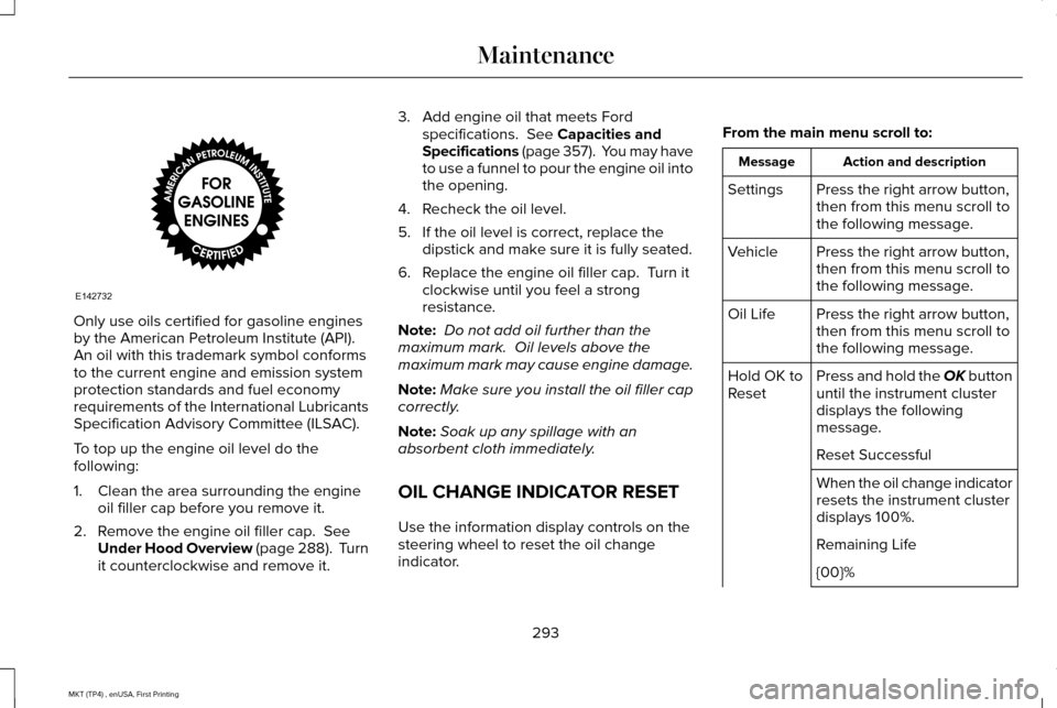
Only use oils certified for gasoline engines
by the American Petroleum Institute (API).
An oil with this trademark symbol conforms
to the current engine and emission system
protection standards and fuel economy
requirements of the International Lubricants
Specification Advisory Committee (ILSAC).
To top up the engine oil level do the
following:
1. Clean the area surrounding the engine
oil filler cap before you remove it.
2. Remove the engine oil filler cap. See
Under Hood Overview (page 288). Turn
it counterclockwise and remove it. 3. Add engine oil that meets Ford
specifications.
See Capacities and
Specifications (page 357). You may have
to use a funnel to pour the engine oil into
the opening.
4. Recheck the oil level.
5. If the oil level is correct, replace the dipstick and make sure it is fully seated.
6. Replace the engine oil filler cap. Turn it clockwise until you feel a strong
resistance.
Note: Do not add oil further than the
maximum mark. Oil levels above the
maximum mark may cause engine damage.
Note: Make sure you install the oil filler cap
correctly.
Note: Soak up any spillage with an
absorbent cloth immediately.
OIL CHANGE INDICATOR RESET
Use the information display controls on the
steering wheel to reset the oil change
indicator. From the main menu scroll to: Action and description
Message
Press the right arrow button,
then from this menu scroll to
the following message.
Settings
Press the right arrow button,
then from this menu scroll to
the following message.
Vehicle
Press the right arrow button,
then from this menu scroll to
the following message.
Oil Life
Press and hold the OK button
until the instrument cluster
displays the following
message.
Hold OK to
Reset
Reset Successful
When the oil change indicator
resets the instrument cluster
displays 100%.
Remaining Life
{00}%
293
MKT (TP4) , enUSA, First Printing MaintenanceE142732
Page 298 of 558
It is very important to use prediluted coolant
approved to the correct specification in order
to avoid plugging the small passageways in
the engine cooling system. See Capacities
and Specifications (page 351). Do not mix
different colors or types of coolant in your
vehicle. Mixing of engine coolants or using
an incorrect coolant may harm the engine or
cooling system components and may not be
covered by the vehicle Warranty.
Note: If prediluted coolant is not available,
use the approved concentrated coolant
diluting it to 50/50 with distilled water.
See
Capacities and Specifications (page 351).
Using water that has not been deionised
may contribute to deposit formation,
corrosion and plugging of the small cooling
system passageways.
Note: Coolants marketed for all makes and
models may not be approved to Ford
specifications and may cause damage to
the cooling system. Resulting component
damage may not be covered by the vehicle
Warranty. If the coolant level is at or below the
minimum mark, add prediluted coolant
immediately.
To top up the coolant level do the following:
1. Unscrew the cap slowly. Any pressure
escapes as you unscrew the cap.
2. Add prediluted coolant approved to the correct specification. See Capacities and
Specifications
(page 351).
3. Add enough prediluted coolant to reach
the correct level.
4. Replace the coolant reservoir cap, turn it clockwise until you feel a strong
resistance.
5. Check the coolant level in the coolant reservoir the next few times you drive
your vehicle. If necessary, add enough
prediluted engine coolant to bring the
coolant level to the correct level.
If you have to add more than
1.1 qt (1 L) of
engine coolant per month, have your vehicle
checked as soon as possible. Operating an
engine with a low level of coolant can result
in engine overheating and possible engine
damage. Note:
During normal vehicle operation, the
coolant may change color from orange to
pink or light red. As long as the coolant is
clear and uncontaminated, this color change
does not indicate the coolant has degraded
nor does it require the coolant to be drained,
the system to be flushed, or the coolant to
be replaced.
In case of emergency, you can add a large
amount of water without engine coolant in
order to reach a vehicle service location. In
this instance, qualified personnel:
1. Must drain the cooling system.
2. Chemically clean the coolant system with
Motorcraft Premium Cooling System
Flush.
3. Refill with engine coolant as soon as possible.
Water alone, without engine coolant, can
cause engine damage from corrosion,
overheating or freezing.
Do not use the following as a coolant
substitute:
• Alcohol.
• Methanol.
295
MKT (TP4) , enUSA, First Printing Maintenance
Page 302 of 558
The transmission does not consume fluid.
However, if the transmission slips or shifts
slowly you should check the fluid level. If you
notice a sign of leaking fluid, contact an
authorized dealer.
Checking the Transmission Fluid Level
WARNING
The dipstick and surrounding
components are hot. Use gloves when
moving components and checking the
transmission fluid level. Failure to follow this
warning could result in serious personal
injury. Only check the transmission fluid level when
the engine is at normal operating
temperature 179°F (82°C)-199°F (93°C).
Normal operating temperature is reached
after driving approximately
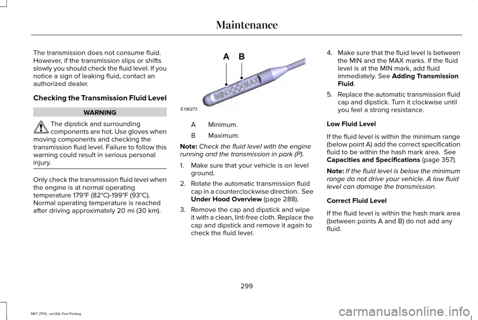
20 mi (30 km). Minimum.
A
Maximum.
B
Note: Check the fluid level with the engine
running and the transmission in park (P).
1. Make sure that your vehicle is on level ground.
2. Rotate the automatic transmission fluid cap in a counterclockwise direction. See
Under Hood Overview
(page 288).
3. Remove the cap and dipstick and wipe it with a clean, lint-free cloth. Replace the
cap and dipstick and remove it again to
check the fluid level. 4.
Make sure that the fluid level is between
the MIN and the MAX marks. If the fluid
level is at the MIN mark, add fluid
immediately. See
Adding Transmission
Fluid.
5. Replace the automatic transmission fluid
cap and dipstick. Turn it clockwise until
you feel a strong resistance.
Low Fluid Level
If the fluid level is within the minimum range
(below point A) add the correct specification
fluid to be within the hash mark area.
See
Capacities and Specifications (page 357).
Note: If the fluid level is below the minimum
range do not drive your vehicle. A low fluid
level can damage the transmission.
Correct Fluid Level
If the fluid level is within the hash mark area
(between points A and B) do not add any
fluid.
299
MKT (TP4) , enUSA, First Printing MaintenanceE190273
AB
Page 303 of 558
High Fluid Level
If the fluid level is above the maximum range
(above point B) fluid may need to be
removed. High fluid levels may be caused
by a overheating condition. If you have
operated your vehicle at high speeds, towing
a trailer or in city traffic during hot weather,
allow your vehicle to cool for a minimum of
30 minutes before rechecking the level.
Note:
An overfill condition can damage the
transmission.
Adding Transmission Fluid *
1. Rotate the automatic transmission fluid cap in a counterclockwise direction.
2. Remove the cap and dipstick and wipe it with a clean, lint-free cloth.
3. Add fluid that meets the Ford specifications. See Capacities and
Specifications (page 357). Pour the fluid
directly into the automatic transmission
fluid cap and dipstick hole.
4. Replace the cap and dipstick and remove
it again to check the fluid level. 5.
Make sure that the fluid level is between
the MIN and the MAX marks.
6. Replace the automatic transmission fluid
cap and dipstick. Turn it clockwise until
you feel a strong resistance.
* Vehicles With EcoBoost Engine WARNING
Do not run the engine with the air filter
disconnected.
1. Loosen the clamp holding the air filter
assembly to the rubber hose.
2. Remove the air filter assembly securing bolts.
3. Lift the air filter assembly to disengage the locating pins.
4. Rotate the air filter assembly slightly in a
counterclockwise direction.
5. Check the transmission fluid level.
6. Install the air filter assembly in reverse order. Tighten the air filter assembly
securing bolts until you feel a strong
resistance. BRAKE FLUID CHECK WARNINGS
Do not use any fluid other than the
recommended brake fluid as this will
reduce brake efficiency. Use of incorrect fluid
could result in the loss of vehicle control,
serious personal injury or death. Only use brake fluid from a sealed
container. Contamination with dirt,
water, petroleum products or other materials
may result in brake system damage or failure.
Failure to adhere to this warning could result
in the loss of vehicle control, serious
personal injury or death. Do not allow the fluid to touch your
skin or eyes. If this happens, rinse the
affected areas immediately with plenty of
water and contact your physician. A fluid level between the MAX and
MIN lines is within the normal
operating range and there is no need to add
fluid. A fluid level not in the normal operating
range could compromise the performance
of the system. Have your vehicle checked
immediately. 300
MKT (TP4) , enUSA, First Printing Maintenance
Page 305 of 558
WARNINGS
Keep batteries out of reach of children.
Batteries contain sulfuric acid. Avoid
contact with skin, eyes or clothing. Shield
your eyes when working near the battery to
protect against possible splashing of acid
solution. In case of acid contact with skin or
eyes, flush immediately with water for a
minimum of 15 minutes and get prompt
medical attention. If acid is swallowed, call a
physician immediately. Battery posts, terminals and related
accessories contain lead and lead
compounds. Wash hands after handling. Your vehicle is fitted with a Motorcraft
maintenance-free battery which normally
does not require additional water.
When a battery replacement is required, you
must use a recommended replacement
battery that matches the electrical
requirements of the vehicle.
Note:
If your vehicle has a battery cover,
after cleaning or replacing the battery, make
sure you reinstall it. Note:
See an authorized dealer for battery
access, testing, or replacement.
To make sure the battery management
system works correctly, do not connect an
electrical device ground connection directly
to the battery negative post. This can cause
inaccurate measurements of the battery
condition and potential incorrect system
operation.
Note: If you add electrical accessories or
components to the vehicle, it may adversely
affect battery performance and durability.
This may also affect the performance of
other electrical systems in the vehicle.
If you see any corrosion on the battery or
terminals, remove the cables from the
terminals and clean with a wire brush. You
can neutralize the acid with a solution of
baking soda and water.
Because your vehicle ’s engine is
electronically-controlled by a computer,
some engine control settings are maintained
by power from the battery. Some engine
computer settings, like the idle trim and fuel
trim strategy, optimize the driveability and performance of the engine. The clock and
radio station presets are also maintained in
memory by power from the low-voltage
battery. These settings are erased when a
technician disconnects and connects the
low-voltage battery.
To restore the settings, do the following:
Note:
Until you switch the ignition to the on
position, you will receive a message in your
information display stating that your vehicle
is not in park.
1. Apply the parking brake.
2. Shift into park (P) or neutral (N).
3. Switch off all accessories.
4. Press the brake pedal and start your vehicle.
5. Run the engine until it reaches normal operating temperature. While the engine
is warming up, complete the following:
Reset the clock. See Audio System
(page 371). Reset the power windows
bounce-back feature. See Windows and
Mirrors
(page 99). Reset the radio station
presets. See Audio System (page 371).
302
MKT (TP4) , enUSA, First Printing Maintenance
Page 308 of 558
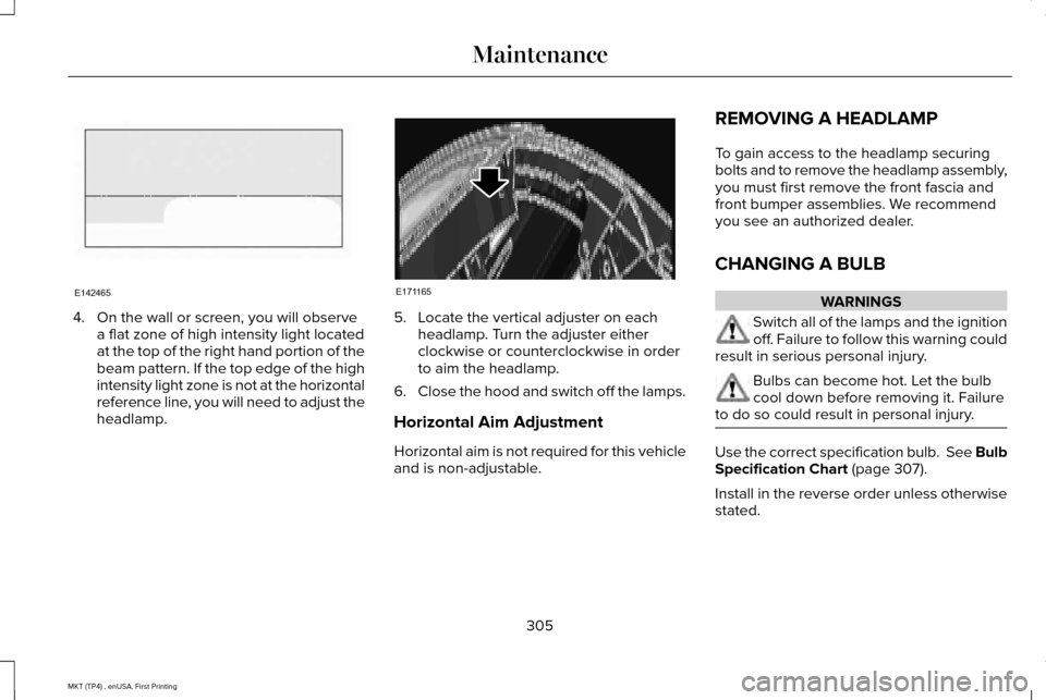
4. On the wall or screen, you will observe
a flat zone of high intensity light located
at the top of the right hand portion of the
beam pattern. If the top edge of the high
intensity light zone is not at the horizontal
reference line, you will need to adjust the
headlamp. 5. Locate the vertical adjuster on each
headlamp. Turn the adjuster either
clockwise or counterclockwise in order
to aim the headlamp.
6. Close the hood and switch off the lamps.
Horizontal Aim Adjustment
Horizontal aim is not required for this vehicle
and is non-adjustable. REMOVING A HEADLAMP
To gain access to the headlamp securing
bolts and to remove the headlamp assembly,
you must first remove the front fascia and
front bumper assemblies. We recommend
you see an authorized dealer.
CHANGING A BULB WARNINGS
Switch all of the lamps and the ignition
off. Failure to follow this warning could
result in serious personal injury. Bulbs can become hot. Let the bulb
cool down before removing it. Failure
to do so could result in personal injury. Use the correct specification bulb. See Bulb
Specification Chart (page 307).
Install in the reverse order unless otherwise
stated.
305
MKT (TP4) , enUSA, First Printing MaintenanceE142465 E171165
Page 309 of 558
High Intensity Discharge Headlamp
These lamps operate at a high voltage. See
an authorized dealer if they fail.
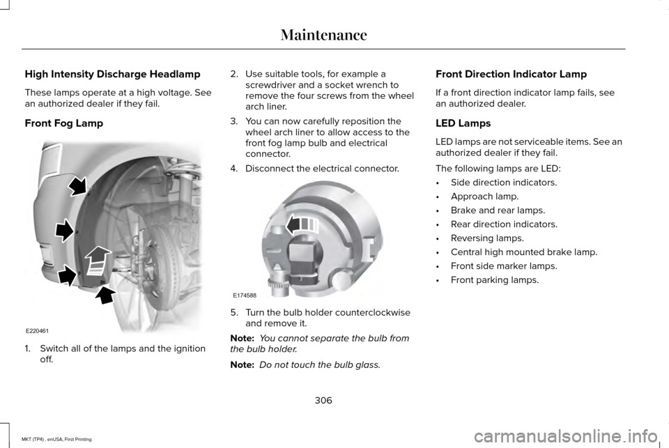
Front Fog Lamp
1. Switch all of the lamps and the ignition
off. 2. Use suitable tools, for example a
screwdriver and a socket wrench to
remove the four screws from the wheel
arch liner.
3. You can now carefully reposition the wheel arch liner to allow access to the
front fog lamp bulb and electrical
connector.
4. Disconnect the electrical connector. 5. Turn the bulb holder counterclockwise
and remove it.
Note: You cannot separate the bulb from
the bulb holder.
Note: Do not touch the bulb glass. Front Direction Indicator Lamp
If a front direction indicator lamp fails, see
an authorized dealer.
LED Lamps
LED lamps are not serviceable items. See an
authorized dealer if they fail.
The following lamps are LED:
•
Side direction indicators.
• Approach lamp.
• Brake and rear lamps.
• Rear direction indicators.
• Reversing lamps.
• Central high mounted brake lamp.
• Front side marker lamps.
• Front parking lamps.
306
MKT (TP4) , enUSA, First Printing MaintenanceE220461 E174588
Page 347 of 558
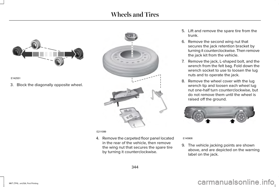
3. Block the diagonally opposite wheel.
4.
Remove the carpeted floor panel located
in the rear of the vehicle, then remove
the wing nut that secures the spare tire
by turning it counterclockwise. 5. Lift and remove the spare tire from the
trunk.
6. Remove the second wing nut that secures the jack retention bracket by
turning it counterclockwise. Then remove
the jack kit from the vehicle.
7. Remove the jack, L-shaped bolt, and the
wrench from the felt bag. Fold down the
wrench socket to use to loosen the lug
nuts and to operate the jack.
8. Remove the wheel cover with the lug wrench tip and loosen each wheel lug
nut one-half turn counterclockwise, but
do not remove them until the wheel is
raised off the ground. 9. The vehicle jacking points are shown
above, and are depicted on the warning
label on the jack.
344
MKT (TP4) , enUSA, First Printing Wheels and TiresE142551 E211099 E145908
Page 348 of 558
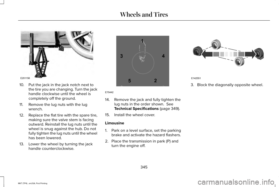
10. Put the jack in the jack notch next to
the tire you are changing. Turn the jack
handle clockwise until the wheel is
completely off the ground.
11. Remove the lug nuts with the lug wrench.
12. Replace the flat tire with the spare tire,
making sure the valve stem is facing
outward. Reinstall the lug nuts until the
wheel is snug against the hub. Do not
fully tighten the lug nuts until the wheel
has been lowered.
13. Lower the wheel by turning the jack handle counterclockwise. 14. Remove the jack and fully tighten the
lug nuts in the order shown. See
Technical Specifications (page 349).
15. Install the wheel cover.
Limousine
1. Park on a level surface, set the parking brake and activate the hazard flashers.
2. Place the transmission in park (P) and turn the engine off. 3. Block the diagonally opposite wheel.
345
MKT (TP4) , enUSA, First Printing Wheels and TiresE201156 12
3
4
5
E75442 E142551