service indicator LINCOLN MKT 2019 Owners Manual
[x] Cancel search | Manufacturer: LINCOLN, Model Year: 2019, Model line: MKT, Model: LINCOLN MKT 2019Pages: 575, PDF Size: 4.66 MB
Page 4 of 575
Introduction
About This Manual...........................................7
Symbols Glossary.............................................7
Data Recording...............................................10
Perchlorate.......................................................12
Lincoln Automotive Financial Services..........................................................................12
Replacement Parts Recommendation..........................................................................12
Special Notices...............................................13
Mobile Communications Equipment.........14
Export Unique Options..................................14
Environment
Protecting the Environment.........................15
At a Glance
Instrument Panel Overview..........................16
Child Safety
General Information.......................................18
Installing Child Restraints............................20
Booster Seats.................................................32
Child Restraint Positioning..........................35
Child Safety Locks.........................................37
Seatbelts
Principle of Operation..................................38
Fastening the Seatbelts...............................39
Seatbelt Height Adjustment........................43
Seatbelt Warning Lamp and IndicatorChime...........................................................44
Seatbelt Reminder.........................................45
Child Restraint and Seatbelt Maintenance.........................................................................46
Seatbelt Extension.........................................47
Personal Safety System™
Personal Safety System™.............................48
Supplementary Restraints System
Principle of Operation..................................49
Driver and Passenger Airbags...................50
Front Passenger Sensing System.............52
Side Airbags....................................................54
Safety Canopy™..............................................55
Crash Sensors and Airbag Indicator.........57
Airbag Disposal..............................................58
Keys and Remote Controls
General Information on Radio Frequencies........................................................................59
Remote Control..............................................60
Replacing a Lost Key or Remote Control.........................................................................63
MyKey™
Principle of Operation..................................64
Creating a MyKey..........................................65
Clearing All MyKeys......................................66
Checking MyKey System Status................66
Using MyKey With Remote Start Systems........................................................................66
MyKey Troubleshooting...............................66
Doors and Locks
Locking and Unlocking................................68
Keyless Entry....................................................71
1
MKT (TP4) , enUSA, Edition date: 201803, Second-Printing
Table of Contents
Page 7 of 575
Cross Traffic Alert........................................222
Steering.........................................................225
Collision Warning System.........................226
Drive Control................................................229
Load Carrying
Rear Under Floor Storage..........................231
Cargo Nets.....................................................231
Luggage Covers...........................................231
Load Limit......................................................232
Towing
Towing a Trailer............................................237
Trailer Sway Control...................................238
Recommended Towing Weights.............238
Essential Towing Checks..........................240
Towing the Vehicle on Four Wheels......243
Driving Hints
Breaking-In...................................................245
Economical Driving.....................................245
Driving Through Water..............................245
Floor Mats.....................................................246
Roadside Emergencies
Roadside Assistance..................................248
Hazard Flashers..........................................249
Fuel Shutoff..................................................249
Jump Starting the Vehicle........................250
Post-Crash Alert System...........................252
Transporting the Vehicle...........................253
Customer Assistance
Getting the Services You Need...............254
In California (U.S. Only)..............................255
The Better Business Bureau (BBB) AutoLine Program (U.S. Only).......................256
Utilizing the Mediation/Arbitration Program(Canada Only)..........................................257
Getting Assistance Outside the U.S. andCanada......................................................258
Ordering Additional Owner's Literature......................................................................260
Reporting Safety Defects (U.S. Only)......260
Reporting Safety Defects (Canada Only).......................................................................261
Fuses
Fuse Specification Chart...........................262
Changing a Fuse.........................................278
Maintenance
General Information....................................281
Opening and Closing the Hood..............282
Under Hood Overview - 3.5L...................283
Under Hood Overview - 3.7L...................284
Engine Oil Dipstick.....................................286
Engine Oil Check........................................286
Oil Change Indicator Reset.......................287
Engine Coolant Check...............................288
Automatic Transmission Fluid Check.....292
Brake Fluid Check......................................294
Power Steering Fluid Check....................295
Washer Fluid Check...................................295
Changing the 12V Battery.........................295
Checking the Wiper Blades......................297
Changing the Wiper Blades.....................297
Adjusting the Headlamps.........................298
Removing a Headlamp..............................300
Changing a Bulb..........................................300
4
MKT (TP4) , enUSA, Edition date: 201803, Second-Printing
Table of Contents
Page 45 of 575
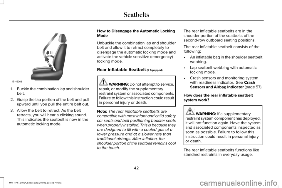
1.Buckle the combination lap and shoulderbelt.
2.Grasp the lap portion of the belt and pullupward until you pull the entire belt out.
3. Allow the belt to retract. As the beltretracts, you will hear a clicking sound.This indicates the seatbelt is now in theautomatic locking mode.
How to Disengage the Automatic LockingMode
Unbuckle the combination lap and shoulderbelt and allow it to retract completely todisengage the automatic locking mode andactivate the vehicle sensitive (emergency)locking mode.
Rear Inflatable Seatbelt (If Equipped)
WARNING: Do not attempt to service,repair, or modify the supplementaryrestraint system or associated components.Failure to follow this instruction could resultin personal injury or death.
Note:The rear inflatable seatbelts arecompatible with most infant and child safetycar seats and belt positioning booster seatswhen properly installed. This is because theyare designed to fill with a cooled gas at alower pressure and at a slower rate thantraditional airbags. After inflation, theshoulder portion of the seatbelt remains coolto the touch.
The rear inflatable seatbelts are in theshoulder portion of the seatbelts of thesecond-row outboard seating positions.
The rear inflatable seatbelt consists of thefollowing:
•An inflatable bag in the shoulder seatbeltwebbing.
•Lap seatbelt webbing with automaticlocking mode.
•Crash sensors and monitoring systemwith readiness indicator. See CrashSensors and Airbag Indicator (page 57).
How does the rear inflatable seatbeltsystem work?
WARNING: If a supplementaryrestraint system component has deployed,it will not function again. Have the systemand associated components inspected assoon as possible. Failure to follow thisinstruction could result in personal injuryor death.
The rear inflatable seatbelts functions likestandard restraints in everyday usage.
42
MKT (TP4) , enUSA, Edition date: 201803, Second-Printing
SeatbeltsE146363
Page 57 of 575
Note:When the passenger airbag statusindicator off light is illuminated, thepassenger (seat mounted) side airbag maybe disabled to avoid the risk of airbagdeployment injuries.
After all occupants have adjusted their seatsand put on seatbelts, it is very important thatthey continue to sit properly. A properlyseated occupant sits upright, leaning againstthe seatback, and centered on the seatcushion, with their feet comfortably extendedon the floor. Sitting improperly can increasethe chance of injury in a crash event. Forexample, if an occupant slouches, lies down,turns sideways, sits forward, leans forwardor sideways, or puts one or both feet up, thechance of injury during a crash greatlyincreases.
Make sure the front passengersensing system is operatingproperly. See Crash Sensors andAirbag Indicator (page 57).
Do not attempt to repair or service thesystem. Take your vehicle immediately to anauthorized dealer.
If it is necessary to modify an advanced frontairbag system to accommodate a personwith disabilities, contact the Ford CustomerRelationship Center. See Getting theServices You Need (page 254).
SIDE AIRBAGS
WARNING: Do not place objects ormount equipment on or near the airbagcover, on the side of the seatbacks (of thefront seats), or in front seat areas that maycome into contact with a deploying airbag.Failure to follow these instructions mayincrease the risk of personal injury in theevent of a crash.
WARNING: Do not use accessoryseat covers. The use of accessory seatcovers may prevent the deployment of theside airbags and increase the risk of injuryin an accident.
WARNING: Do not lean your headon the door. The side airbag could injureyou as it deploys from the side of theseatback.
WARNING: Do not attempt to service,repair, or modify the airbag, its fuses or theseat cover on a seat containing an airbagas you could be seriously injured or killed.Contact your authorized dealer as soon aspossible.
WARNING: If the side airbag hasdeployed, the airbag will not functionagain. The side airbag system (includingthe seat) must be inspected and servicedby an authorized dealer. If the airbag is notreplaced, the unrepaired area will increasethe risk of injury in a crash.
54
MKT (TP4) , enUSA, Edition date: 201803, Second-Printing
Supplementary Restraints SystemE67017
Page 58 of 575
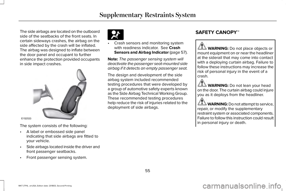
The side airbags are located on the outboardside of the seatbacks of the front seats. Incertain sideways crashes, the airbag on theside affected by the crash will be inflated.The airbag was designed to inflate betweenthe door panel and occupant to furtherenhance the protection provided occupantsin side impact crashes.
The system consists of the following:
•A label or embossed side panelindicating that side airbags are fitted toyour vehicle.
•Side airbags located inside the driver andfront passenger seatbacks.
•Front passenger sensing system.
•Crash sensors and monitoring systemwith readiness indicator. See CrashSensors and Airbag Indicator (page 57).
Note:The passenger sensing system willdeactivate the passenger seat-mounted sideairbag if it detects an empty passenger seat.
The design and development of the sideairbag system included recommendedtesting procedures that were developed bya group of automotive safety experts knownas the Side Airbag Technical Working Group.These recommended testing procedureshelp reduce the risk of injuries related to thedeployment of side airbags.
SAFETY CANOPY™
WARNING: Do not place objects ormount equipment on or near the headlinerat the siderail that may come into contactwith a deploying curtain airbag. Failure tofollow these instructions may increase therisk of personal injury in the event of acrash.
WARNING: Do not lean your headon the door. The curtain airbag could injureyou as it deploys from the headliner.
WARNING: Do not attempt to service,repair, or modify the supplementaryrestraint system or associated components.Failure to follow this instruction could resultin personal injury or death.
55
MKT (TP4) , enUSA, Edition date: 201803, Second-Printing
Supplementary Restraints SystemE152533 E67017
Page 60 of 575
The design and development of the SafetyCanopy included recommended testingprocedures that were developed by a groupof automotive safety experts known as theSide Airbag Technical Working Group. Theserecommended testing procedures helpreduce the risk of injuries related to thedeployment of side airbags (including theSafety Canopy).
CRASH SENSORS AND AIRBAG
INDICATOR
WARNING: Modifying or addingequipment to the front end of the vehicle(including frame, bumper, front end bodystructure and tow hooks) may affect theperformance of the airbag system,increasing the risk of injury. Do not modifythe front end of the vehicle.
Your vehicle has a collection of crash andoccupant sensors which provide informationto the restraints control module. Therestraints control module deploys (activates)the front safety belt pretensioners, driverairbag, passenger airbag, seat mounted sideairbags, the Safety Canopy and rearinflatable safety belts. Based on the type ofcrash, the restraints control module willdeploy the appropriate safety devices.
The restraints control module also monitorsthe readiness of the above safety devicesplus the crash and occupant sensors. Thereadiness of the safety system is indicatedby a warning indicator light in the instrumentcluster or by a backup tone if the warninglight is not working. Routine maintenance ofthe airbag is not required.
A difficulty with the system is indicated byone or more of the following:
The readiness light will notilluminate immediately after theignition is turned on.
•The readiness light will either flash orstay lit.
•A series of five beeps will be heard. Thetone pattern will repeat periodically untilthe problem, the light or both arerepaired.
If any of these things happen, evenintermittently, have the supplementalrestraint system serviced at an authorizeddealer immediately. Unless serviced, thesystem may not function properly in theevent of a crash.
57
MKT (TP4) , enUSA, Edition date: 201803, Second-Printing
Supplementary Restraints SystemE67017
Page 65 of 575
•The battery voltage is below theminimum operating voltage.
•The service engine soon indicator wason the last time your vehicle was driven.
Remote Starting your Vehicle
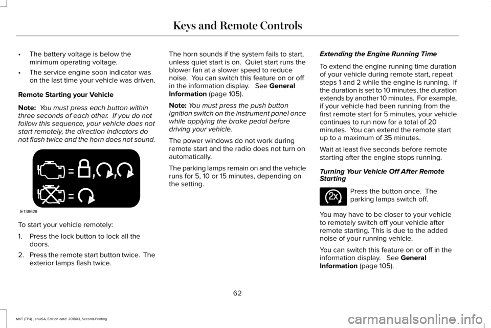
Note: You must press each button withinthree seconds of each other. If you do notfollow this sequence, your vehicle does notstart remotely, the direction indicators donot flash twice and the horn does not sound.
To start your vehicle remotely:
1. Press the lock button to lock all thedoors.
2.Press the remote start button twice. Theexterior lamps flash twice.
The horn sounds if the system fails to start,unless quiet start is on. Quiet start runs theblower fan at a slower speed to reducenoise. You can switch this feature on or offin the information display. See GeneralInformation (page 105).
Note:You must press the push buttonignition switch on the instrument panel oncewhile applying the brake pedal beforedriving your vehicle.
The power windows do not work duringremote start and the radio does not turn onautomatically.
The parking lamps remain on and the vehicleruns for 5, 10 or 15 minutes, depending onthe setting.
Extending the Engine Running Time
To extend the engine running time durationof your vehicle during remote start, repeatsteps 1 and 2 while the engine is running. Ifthe duration is set to 10 minutes, the durationextends by another 10 minutes. For example,if your vehicle had been running from thefirst remote start for 5 minutes, your vehiclecontinues to run now for a total of 20minutes. You can extend the remote startup to a maximum of 35 minutes.
Wait at least five seconds before remotestarting after the engine stops running.
Turning Your Vehicle Off After RemoteStarting
Press the button once. Theparking lamps switch off.
You may have to be closer to your vehicleto remotely switch off your vehicle afterremote starting. This is due to the addednoise of your running vehicle.
You can switch this feature on or off in theinformation display. See GeneralInformation (page 105).
62
MKT (TP4) , enUSA, Edition date: 201803, Second-Printing
Keys and Remote ControlsE138626 E138625
Page 118 of 575
AWD
ActionMessage
Displays if the AWD system disables to protect itself. This may occur if you operate the vehicleafter installing the compact spare tire, if the system is overheating or if there is an issue withanother vehicle system that prevents the AWD system from operating. The AWD system resumesnormal operation and clears this message after you install the road tire and you switch the ignitionon and off, or after you allow the system to cool. If this message remains on, have a qualifiedtechnician service your vehicle to repair other vehicle systems.
AWD OFF
Displayed in conjunction with the Throttle Control / Transmission / AWD light when the AWDsystem is not operating properly. See Warning Lamps and Indicators (page 101). If the warningstays illuminated or continues to illuminate, contact an authorized dealer as soon as possible.
Check AWD
115
MKT (TP4) , enUSA, Edition date: 201803, Second-Printing
Information Displays
Page 176 of 575
The scheduled maintenance items listed inscheduled maintenance information areessential to the life and performance of yourvehicle and to its emissions system.
If you use anything other than Lincoln,Motorcraft or Lincoln-authorized parts formaintenance replacements or for service ofcomponents affecting emission control, suchnon-Lincoln parts should be equivalent togenuine Lincoln Motor Company parts inperformance and durability.
Illumination of the service engine soonindicator, charging system warning light orthe temperature warning light, fluid leaks,strange odors, smoke or loss of enginepower could indicate that the emissioncontrol system is not working properly.
An improperly operating or damaged exhaustsystem may allow exhaust to enter thevehicle. Have a damaged or improperlyoperating exhaust system inspected andrepaired immediately.
Do not make any unauthorized changes toyour vehicle or engine. By law, vehicleowners and anyone who manufactures,repairs, services, sells, leases, tradesvehicles, or supervises a fleet of vehicles arenot permitted to intentionally remove anemission control device or prevent it fromworking. Information about your vehicle’semission system is on the Vehicle EmissionControl Information Decal located on or nearthe engine. This decal also lists enginedisplacement.
Please consult your warranty information forcomplete details.
On-Board Diagnostics (OBD-II)
Your vehicle has a computer known as theon-board diagnostics system (OBD-II) thatmonitors the engine’s emission controlsystem. The system protects the environmentby making sure that your vehicle continuesto meet government emission standards. TheOBD-II system also assists a servicetechnician in properly servicing your vehicle.
When the service engine soonindicator illuminates, the OBD-IIsystem has detected a malfunction.Temporary malfunctions may cause theservice engine soon indicator to illuminate.Examples are:
1. Your vehicle has run out of fuel—theengine may misfire or run poorly.
2.Poor fuel quality or water in the fuel—theengine may misfire or run poorly.
3. The fuel fill inlet may not have closedproperly. See Refueling (page 167).
4. Driving through deep water—theelectrical system may be wet.
You can correct these temporarymalfunctions by filling the fuel tank with goodquality fuel, properly closing the fuel fill inletor letting the electrical system dry out. Afterthree driving cycles without these or anyother temporary malfunctions present, theservice engine soon indicator should stay offthe next time you start the engine. A drivingcycle consists of a cold engine startupfollowed by mixed city and highway driving.No additional vehicle service is required.
173
MKT (TP4) , enUSA, Edition date: 201803, Second-Printing
Engine Emission Control
Page 177 of 575
If the service engine soon indicator remainson, have your vehicle serviced at the firstavailable opportunity. Although somemalfunctions detected by the OBD-II may nothave symptoms that are apparent, continueddriving with the service engine soon indicatoron can result in increased emissions, lowerfuel economy, reduced engine andtransmission smoothness and lead to morecostly repairs.
Readiness for Inspection andMaintenance (I/M) Testing
Some state and provincial and localgovernments may haveInspection/Maintenance (I/M) programs toinspect the emission control equipment onyour vehicle. Failure to pass this inspectioncould prevent you from getting a vehicleregistration.
If the service engine soon indicatoris on or the bulb does not work,your vehicle may need service.See On-Board Diagnostics.
Your vehicle may not pass the I/M test if theservice engine soon indicator is on or notworking properly (bulb is burned out), or ifthe OBD-II system has determined that someof the emission control systems have notbeen properly checked. In this case, thevehicle is not ready for I/M testing.
If the vehicle’s engine or transmission hasjust been serviced, or the battery hasrecently run down or been replaced, theOBD-II system may indicate that the vehicleis not ready for I/M testing. To determine ifthe vehicle is ready for I/M testing, turn theignition key to the on position for 15 secondswithout cranking the engine. If the serviceengine soon indicator blinks eight times, itmeans that the vehicle is not ready for I/Mtesting; if the service engine soon indicatorstays on solid, it means that your vehicle isready for I/M testing.
The OBD-II system checks the emissioncontrol system during normal driving. Acomplete check may take several days.
If the vehicle is not ready for I/M testing, youcan perform the following driving cycleconsisting of mixed city and highway driving:
1. 15 minutes of steady driving on anexpressway or highway followed by 20minutes of stop-and-go driving with atleast four 30-second idle periods.
2.Allow your vehicle to sit for at least eighthours with the ignition off. Then, start thevehicle and complete the above drivingcycle. The vehicle must warm up to itsnormal operating temperature. Oncestarted, do not turn off the vehicle untilthe above driving cycle is complete.
If the vehicle is still not ready for I/M testing,you need to repeat the above driving cycle.
174
MKT (TP4) , enUSA, Edition date: 201803, Second-Printing
Engine Emission Control