side mirror LINCOLN MKZ 2007 Owners Manual
[x] Cancel search | Manufacturer: LINCOLN, Model Year: 2007, Model line: MKZ, Model: LINCOLN MKZ 2007Pages: 272, PDF Size: 2.24 MB
Page 29 of 272
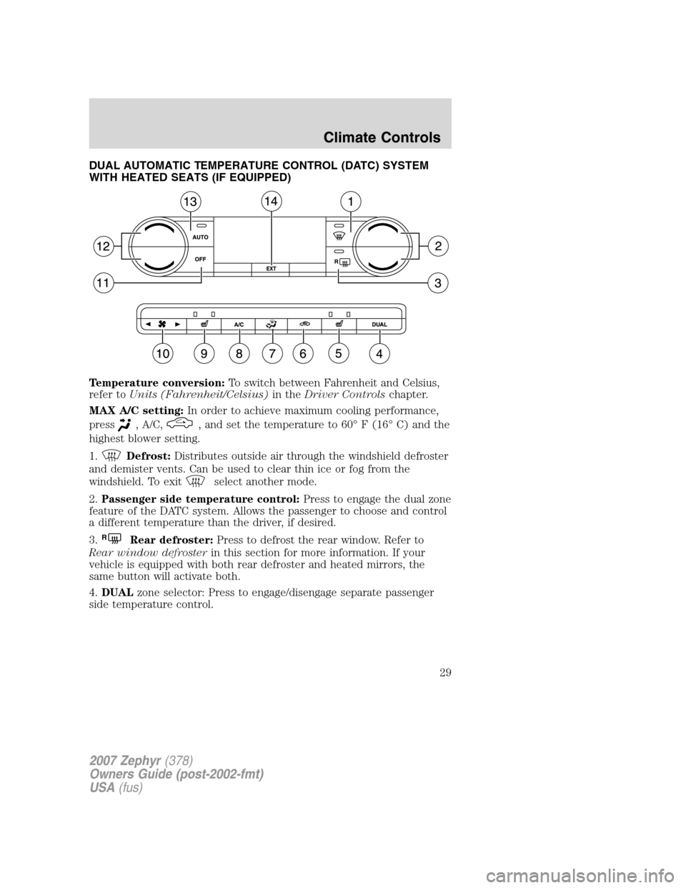
DUAL AUTOMATIC TEMPERATURE CONTROL (DATC) SYSTEM
WITH HEATED SEATS (IF EQUIPPED)
Temperature conversion:To switch between Fahrenheit and Celsius,
refer toUnits (Fahrenheit/Celsius)in theDriver Controlschapter.
MAX A/C setting:In order to achieve maximum cooling performance,
press
, A/C,, and set the temperature to 60° F (16° C) and the
highest blower setting.
1.
Defrost:Distributes outside air through the windshield defroster
and demister vents. Can be used to clear thin ice or fog from the
windshield. To exit
select another mode.
2.Passenger side temperature control:Press to engage the dual zone
feature of the DATC system. Allows the passenger to choose and control
a different temperature than the driver, if desired.
3.
RRear defroster:Press to defrost the rear window. Refer to
Rear window defrosterin this section for more information. If your
vehicle is equipped with both rear defroster and heated mirrors, the
same button will activate both.
4.DUALzone selector: Press to engage/disengage separate passenger
side temperature control.
2007 Zephyr(378)
Owners Guide (post-2002-fmt)
USA(fus)
Climate Controls
29
Page 52 of 272
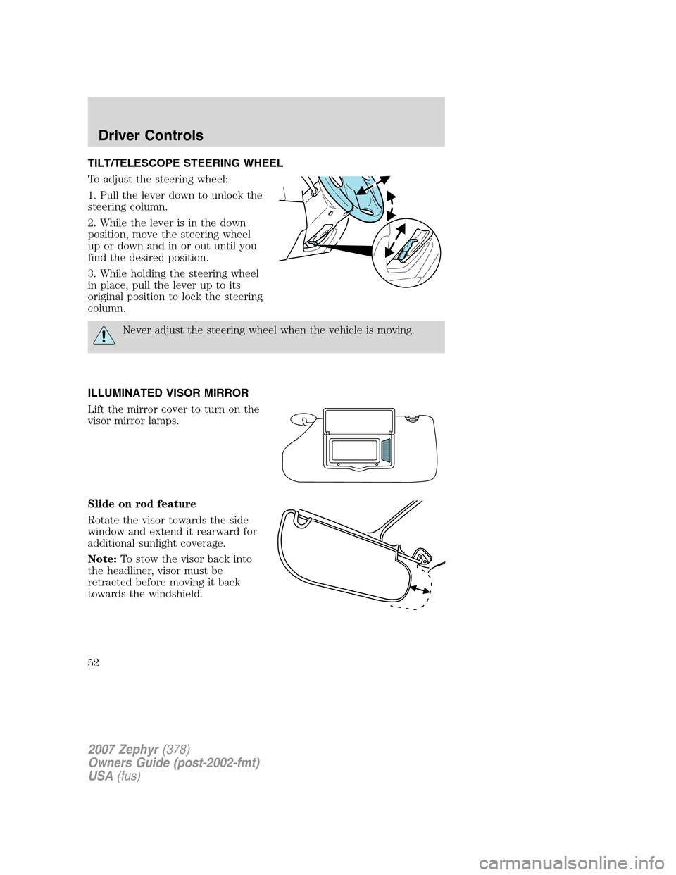
TILT/TELESCOPE STEERING WHEEL
To adjust the steering wheel:
1. Pull the lever down to unlock the
steering column.
2. While the lever is in the down
position, move the steering wheel
up or down and in or out until you
find the desired position.
3. While holding the steering wheel
in place, pull the lever up to its
original position to lock the steering
column.
Never adjust the steering wheel when the vehicle is moving.
ILLUMINATED VISOR MIRROR
Lift the mirror cover to turn on the
visor mirror lamps.
Slide on rod feature
Rotate the visor towards the side
window and extend it rearward for
additional sunlight coverage.
Note:To stow the visor back into
the headliner, visor must be
retracted before moving it back
towards the windshield.
2007 Zephyr(378)
Owners Guide (post-2002-fmt)
USA(fus)
Driver Controls
52
Page 57 of 272
AUTOMATIC DIMMING REAR VIEW MIRRORS
Your vehicle is equipped with an
inside rear view mirror and a
driver’s outside mirror that has an
auto-dimming function. The
electronic day/night mirror will
change from the normal (high
reflective) state to the non-glare
(darkened) state when bright lights
(glare) reach the inside mirror. When the inside mirror detects bright
light from behind the vehicle, the inside rear view mirror and the driver’s
outside mirror will automatically adjust (darken) to minimize glare.
The mirrors will automatically return to the normal state whenever the
vehicle is placed in R (Reverse) to ensure a bright clear view when
backing up.
Do not block the sensors on the front and back of the inside rear view
mirror since this may impair proper mirror performance.
EXTERIOR MIRRORS
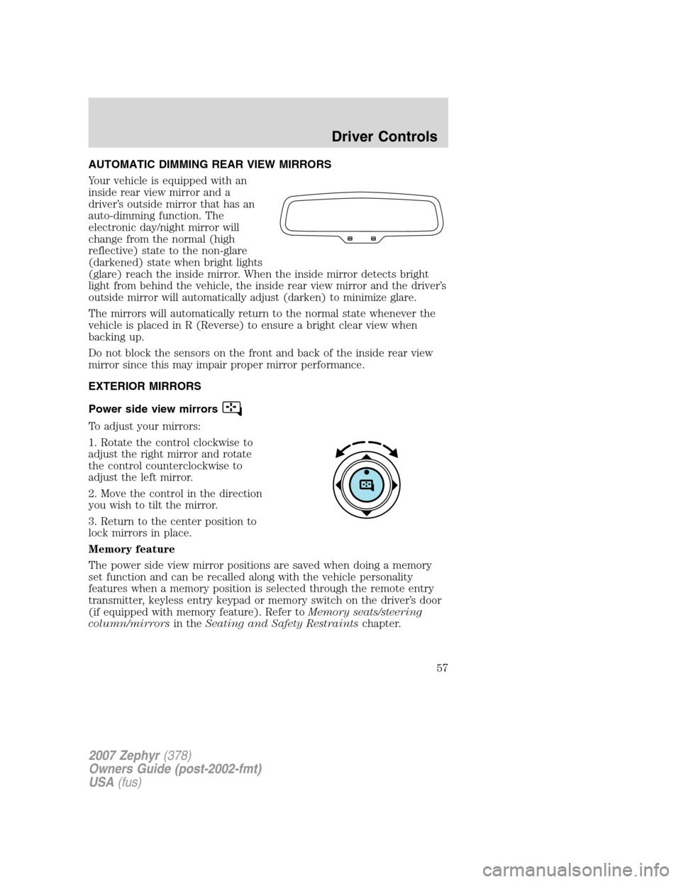
Power side view mirrors
To adjust your mirrors:
1. Rotate the control clockwise to
adjust the right mirror and rotate
the control counterclockwise to
adjust the left mirror.
2. Move the control in the direction
you wish to tilt the mirror.
3. Return to the center position to
lock mirrors in place.
Memory feature
The power side view mirror positions are saved when doing a memory
set function and can be recalled along with the vehicle personality
features when a memory position is selected through the remote entry
transmitter, keyless entry keypad or memory switch on the driver’s door
(if equipped with memory feature). Refer toMemory seats/steering
column/mirrorsin theSeating and Safety Restraintschapter.
2007 Zephyr(378)
Owners Guide (post-2002-fmt)
USA(fus)
Driver Controls
57
Page 103 of 272
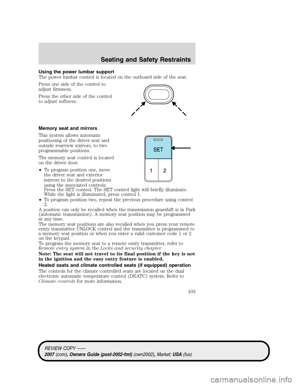
Using the power lumbar support
The power lumbar control is located on the outboard side of the seat.
Press one side of the control to
adjust firmness.
Press the other side of the control
to adjust softness.
Memory seat and mirrors
This system allows automatic
positioning of the driver seat and
outside rearview mirrors, to two
programmable positions.
The memory seat control is located
on the driver door.
•To program position one, move
the driver seat and exterior
mirrors to the desired positions
using the associated controls.
Press the SET control. The SET control light will briefly illuminate.
While the light is illuminated, press control 1.
•To program position two, repeat the previous procedure using control
2.
A position can only be recalled when the transmission gearshift is in Park
(automatic transmission). A memory seat position may be programmed
at any time.
The memory seat positions are also recalled when you press your remote
entry transmitter UNLOCK control and the transmitter is programmed to
a memory seat position or when you enter a valid customer code 1 or 2
on the keypad.
To program the memory seat to a remote entry transmitter, refer to
Remote entry systemin theLocks and security chapter.
Note: The seat will not travel to its final position if the key is not
in the ignition and the easy entry feature is enabled.
Heated seats and climate controlled seats (if equipped) operation
The controls for the climate controlled seats are located on the dual
electronic automatic temperature control (DEATC) system. Refer to
Climate controlsfor more information.
REVIEW COPY ——
2007(com), Owners Guide (post-2002-fmt)(own2002),Market:USA(fus)
Seating and Safety Restraints
103
Page 191 of 272
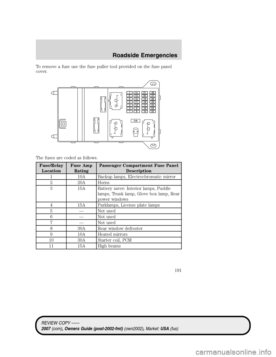
To remove a fuse use the fuse puller tool provided on the fuse panel
cover.
The fuses are coded as follows.
Fuse/Relay
LocationFuse Amp
RatingPassenger Compartment Fuse Panel
Description
1 10A Backup lamps, Electrochromatic mirror
2 20A Horns
3 15A Battery saver: Interior lamps, Puddle
lamps, Trunk lamp, Glove box lamp, Rear
power windows
4 15A Parklamps, License plate lamps
5 — Not used
6 — Not used
7 — Not used
8 30A Rear window defroster
9 10A Heated mirrors
10 30A Starter coil, PCM
11 15A High beams
REVIEW COPY ——
2007(com), Owners Guide (post-2002-fmt)(own2002),Market:USA(fus)
Roadside Emergencies
191
Page 192 of 272
Fuse/Relay
LocationFuse Amp
RatingPassenger Compartment Fuse Panel
Description
12 7.5A Delay accessories: Radio head units,
Moon roof, Front power windows,
Electrochromatic mirrors
13 7.5A Cluster, Analog clock, Climate control
head units
14 15A Washer pump
15 20A Cigar lighter
16 15A Door lock actuator, Decklid lock solenoid
17 20A Not used (Spare)
18 20A Radio head units, OBDII connector
19 7.5A Not used (Spare)
20 7.5A Power mirrors, Satellite radio module, All
wheel drive
21 7.5A Stop lamps, CHMSL
22 7.5A Audio
23 7.5A Wiper relay coil, Cluster logic
24 7.5A OCS (Passenger’s seat), PAD indicator
25 7.5A RCM
26 7.5A PATS Transceiver, Brake shift interlock
solenoid, Brake pedal switch, Automatic
transmission module
27 7.5A Cluster, Climate control head units
28 10A ABS/Traction Control, Heated seats,
Compass
C/B 30A Circuit
BreakerMoon roof, Delayed accessory (SJB fuse
12, rear power windows)
Power distribution box
The power distribution box is located in the engine compartment. The
power distribution box contains high-current fuses that protect your
vehicle’s main electrical systems from overloads.
Always disconnect the battery before servicing high current
fuses.
REVIEW COPY ——
2007(com), Owners Guide (post-2002-fmt)(own2002),Market:USA(fus)
Roadside Emergencies
192
Page 193 of 272
To reduce risk of electrical shock, always replace the cover to
the Power Distribution Box before reconnecting the battery or
refilling fluid reservoirs.
If the battery has been disconnected and reconnected, refer to the
Batterysection of theMaintenance and Specificationschapter.
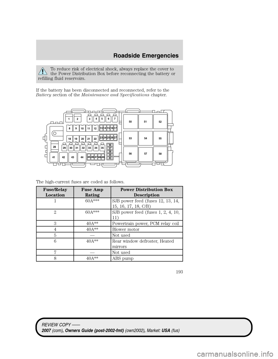
The high-current fuses are coded as follows.
Fuse/Relay
LocationFuse Amp
RatingPower Distribution Box
Description
1 60A*** SJB power feed (fuses 12, 13, 14,
15, 16, 17, 18, C/B)
2 60A*** SJB power feed (fuses 1, 2, 4, 10,
11)
3 40A** Powertrain power, PCM relay coil
4 40A** Blower motor
5 — Not used
6 40A** Rear window defroster, Heated
mirrors
7 — Not used
8 40A** ABS pump
45 46 47
48 4950 51
52
53
55
5654
57
58
41 42 43 44
23 24 25 26 27
28
29 30 31 32 33 34 35
13 12
89
10 11 12
18 19 20 21 22345 6 7
1415
16
17
36
37
38
39
40
REVIEW COPY ——
2007(com), Owners Guide (post-2002-fmt)(own2002),Market:USA(fus)
Roadside Emergencies
193
Page 216 of 272
WAXING
Applying Motorcraft Paint Sealant (ZC-45) to your vehicle every six
months will assist in reducing minor scratches and paint damage.
•Wash the vehicle first.
•Do not use waxes that contain abrasives; use Motorcraft Premium
Liquid Wax (ZC-53-A), which is available from your authorized dealer,
or an equivalent quality product.
•Do not allow paint sealant to come in contact with any non-body
(low-gloss black) colored trim, such as grained door handles, roof
racks, bumpers, side moldings, mirror housings or the windshield cowl
area. The paint sealant will “gray” or stain the parts over time.
PAINT CHIPS
Your authorized dealer has touch-up paint and sprays to match your
vehicle’s color. Take your color code (printed on a sticker in the driver’s
door jamb) to your authorized dealer to ensure you get the correct color.
•Remove particles such as bird droppings, tree sap, insect deposits, tar
spots, road salt and industrial fallout before repairing paint chips.
•Always read the instructions before using the products.
ALUMINUM WHEELS AND WHEEL COVERS
Aluminum wheels and wheel covers are coated with a clearcoat paint
finish. In order to maintain their shine:
•Clean weekly with Motorcraft Wheel and Tire Cleaner (ZC-37–A),
which is available from your authorized dealer. Heavy dirt and brake
dust accumulation may require agitation with a sponge. Rinse
thoroughly with a strong stream of water.
•Never apply any cleaning chemical to hot or warm wheel rims or
covers.
•Some automatic car washes may cause damage to the finish on your
wheel rims or covers. Chemical-strength cleaners, or cleaning
chemicals, in combination with brush agitation to remove brake dust
and dirt, could wear away the clearcoat finish over time.
•Do not use hydrofluoric acid-based or high caustic-based wheel
cleaners, steel wool, fuels or strong household detergent.
•To remove tar and grease, use Motorcraft Bug and Tar Remover
(ZC-42), available from your authorized dealer.
REVIEW COPY ——
2007(com), Owners Guide (post-2002-fmt)(own2002),Market:USA(fus)
Cleaning
216
Page 264 of 272
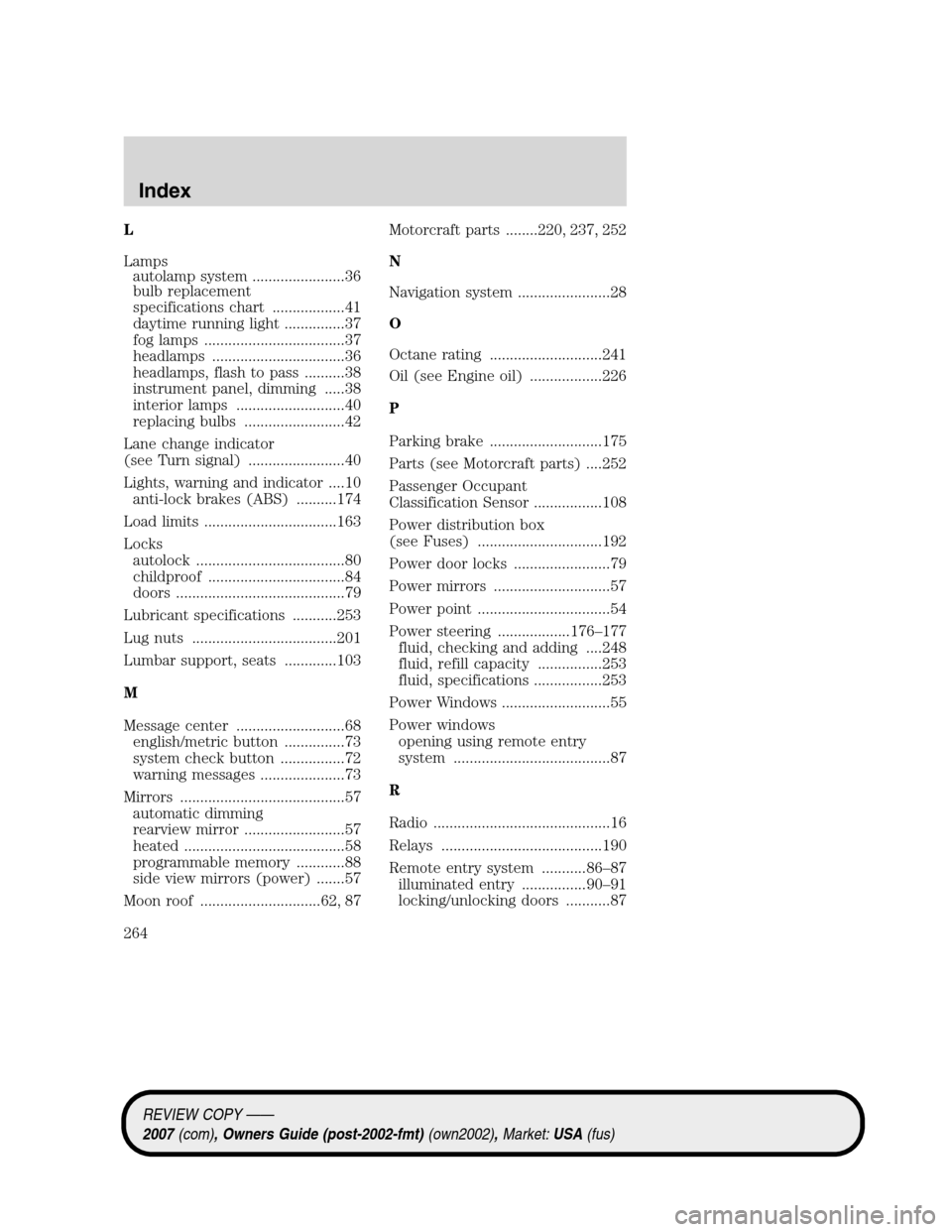
L
Lamps
autolamp system .......................36
bulb replacement
specifications chart ..................41
daytime running light ...............37
fog lamps ...................................37
headlamps .................................36
headlamps, flash to pass ..........38
instrument panel, dimming .....38
interior lamps ...........................40
replacing bulbs .........................42
Lane change indicator
(see Turn signal) ........................40
Lights, warning and indicator ....10
anti-lock brakes (ABS) ..........174
Load limits .................................163
Locks
autolock .....................................80
childproof ..................................84
doors ..........................................79
Lubricant specifications ...........253
Lug nuts ....................................201
Lumbar support, seats .............103
M
Message center ...........................68
english/metric button ...............73
system check button ................72
warning messages .....................73
Mirrors .........................................57
automatic dimming
rearview mirror .........................57
heated ........................................58
programmable memory ............88
side view mirrors (power) .......57
Moon roof ..............................62, 87Motorcraft parts ........220, 237, 252
N
Navigation system .......................28
O
Octane rating ............................241
Oil (see Engine oil) ..................226
P
Parking brake ............................175
Parts (see Motorcraft parts) ....252
Passenger Occupant
Classification Sensor .................108
Power distribution box
(see Fuses) ...............................192
Power door locks ........................79
Power mirrors .............................57
Power point .................................54
Power steering ..................176–177
fluid, checking and adding ....248
fluid, refill capacity ................253
fluid, specifications .................253
Power Windows ...........................55
Power windows
opening using remote entry
system .......................................87
R
Radio ............................................16
Relays ........................................190
Remote entry system ...........86–87
illuminated entry ................90–91
locking/unlocking doors ...........87
REVIEW COPY ——
2007(com), Owners Guide (post-2002-fmt)(own2002),Market:USA(fus)
Index
264