brake LINCOLN MKZ 2013 Repair Manual
[x] Cancel search | Manufacturer: LINCOLN, Model Year: 2013, Model line: MKZ, Model: LINCOLN MKZ 2013Pages: 474, PDF Size: 3.79 MB
Page 239 of 474
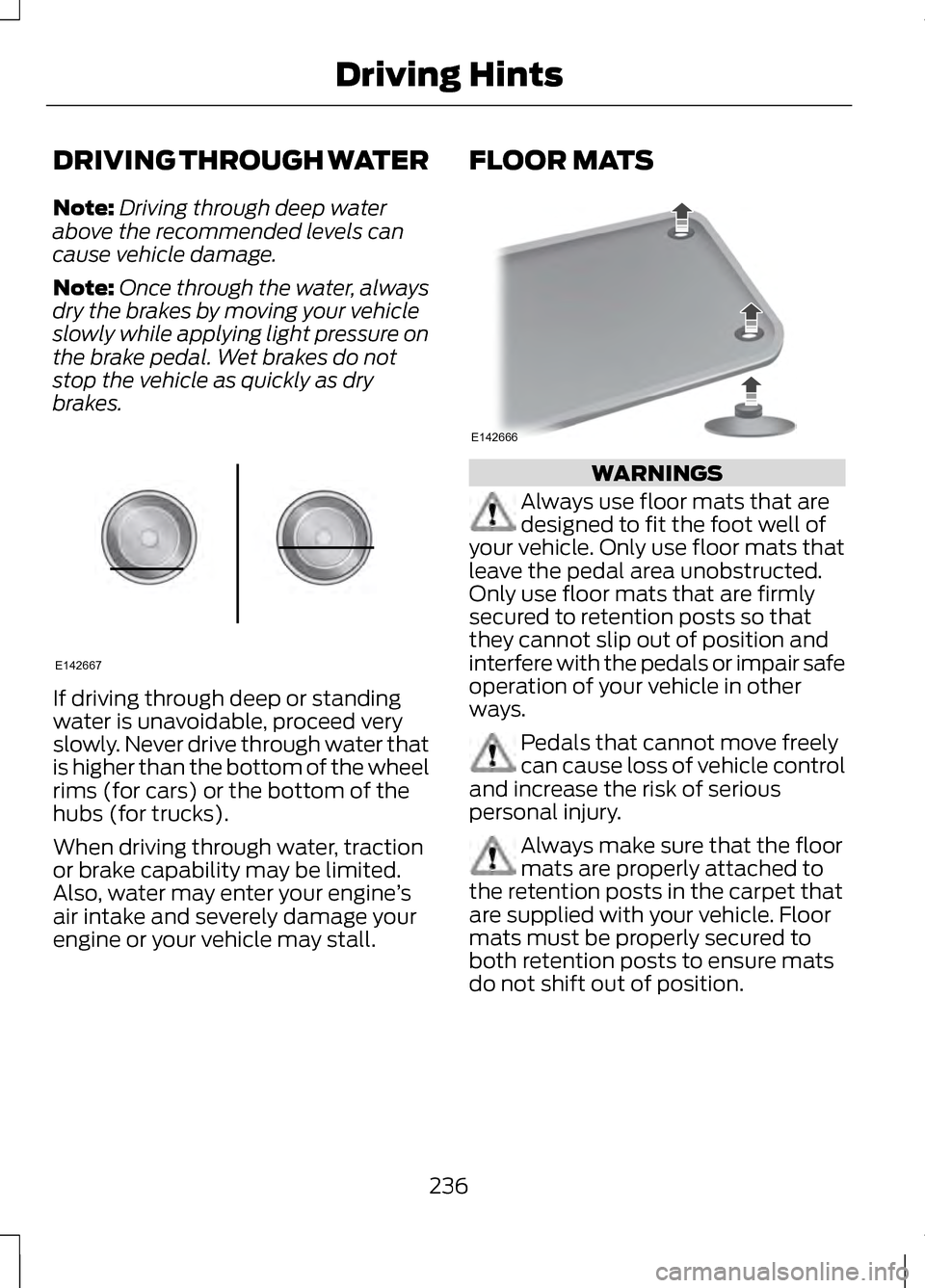
DRIVING THROUGH WATER
Note:
Driving through deep water
above the recommended levels can
cause vehicle damage.
Note: Once through the water, always
dry the brakes by moving your vehicle
slowly while applying light pressure on
the brake pedal. Wet brakes do not
stop the vehicle as quickly as dry
brakes. If driving through deep or standing
water is unavoidable, proceed very
slowly. Never drive through water that
is higher than the bottom of the wheel
rims (for cars) or the bottom of the
hubs (for trucks).
When driving through water, traction
or brake capability may be limited.
Also, water may enter your engine
’s
air intake and severely damage your
engine or your vehicle may stall. FLOOR MATS
WARNINGS
Always use floor mats that are
designed to fit the foot well of
your vehicle. Only use floor mats that
leave the pedal area unobstructed.
Only use floor mats that are firmly
secured to retention posts so that
they cannot slip out of position and
interfere with the pedals or impair safe
operation of your vehicle in other
ways. Pedals that cannot move freely
can cause loss of vehicle control
and increase the risk of serious
personal injury. Always make sure that the floor
mats are properly attached to
the retention posts in the carpet that
are supplied with your vehicle. Floor
mats must be properly secured to
both retention posts to ensure mats
do not shift out of position.
236
Driving HintsE142667 E142666
Page 243 of 474
1. Turn the ignition off.
2. Turn the ignition to crank.
3. Turn the ignition off.
4. Turn the ignition on again to
re-enable the fuel pump.
For vehicles equipped with a push
button start system:
1. Press the START/STOP button
to turn the ignition off.
2. Press the brake pedal and press the
START/STOP button (crank
attempt).
3. Remove your foot from the brake pedal and press the
START/STOP
button (ignition
off).
4. Press the
START/STOP button
again to re-enable the fuel system.
JUMP-STARTING THE
VEHICLE WARNINGS
The gases around the battery
can explode if exposed to
flames, sparks, or lit cigarettes. An
explosion could result in injury or
vehicle damage. Batteries contain sulfuric acid
which can burn skin, eyes and
clothing, if contacted. Only use an adequate sized
cable with insulated clamps. Preparing Your Vehicle
Note:
Use only a 12-volt supply to start
your vehicle.
Note: Do not disconnect the battery
of the disabled vehicle as this could
damage the vehicle's electrical system.
Park the booster vehicle close to the
hood of the disabled vehicle, making
sure the two vehicles do not touch.
Turn all accessories off.
Connecting the Jumper Cables WARNING
Do not attach the cables to fuel
lines, engine rocker covers, the
intake manifold or electrical
components as grounding points. Stay
clear of moving parts. Note:
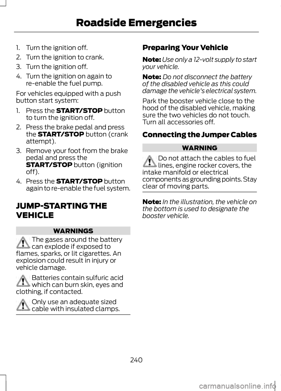
In the illustration, the vehicle on
the bottom is used to designate the
booster vehicle.
240
Roadside Emergencies
Page 257 of 474
Protected components
Fuse amp rating
Fuse or relay
number
Electronic power assist steering
10A 1
19
Run/start lighting
10A 1
20
Run/start transmission control,
Transmission oil pump start/stop
15A
1
21
Air conditioner clutch solenoid
10A 1
22
Blind spot information system, Rear
view camera, Adaptive cruise control,
Heads-up display, Shifter
15A
1
23
Not used
-
24
Anti-lock brake system
10A 2
25
Powertrain control module
10A 2
26
Not used
-
27
Not used
-
28
Not used
-
29
Not used
-
30
Not used
-
31
Electronic fan #1 relay
-
32
Air conditioner clutch relay
-
33
Not used
-
34
Not used
-
35
Not used
-
36
Not used
-
37
Electronic fan #2 relay
-
38
Electronic fan #3 relay
-
39
254
Fuses
Page 258 of 474
Protected components
Fuse amp rating
Fuse or relay
number
Fuel pump relay
-
40
Horn relay
-
41
Not used
-
42
Not used
-
43
Not used
-
44
Not used
-
45
Alternator
10A 2
46
Brake on/off switch
10A 2
47
Horn
20A 1
48
Mass air flow monitor
5A 1
49
Not used
-
50
Not used
-
51
Not used
-
52
Power seats
10A 1
53
Not used
-
54
Not used
-
55
1 Micro fuse
2 Dual micro fuse
3 M-type fuse
Power Distribution Box - Bottom
There are fuses located on the bottom
of the fuse box. To access the bottom
of the fuse box, do the following:
255
Fuses
Page 261 of 474
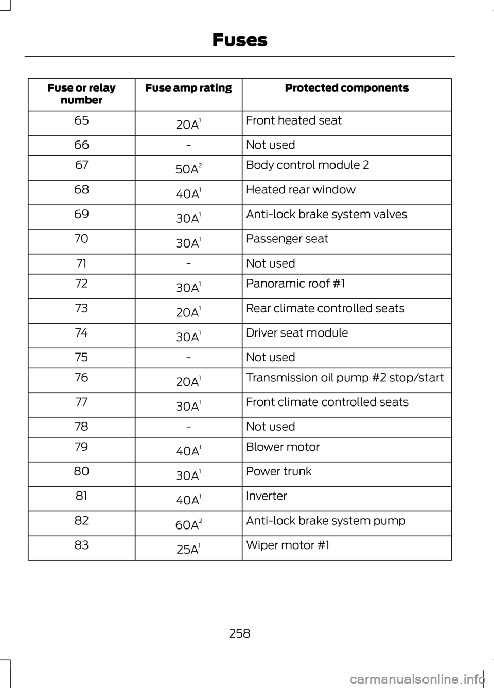
Protected components
Fuse amp rating
Fuse or relay
number
Front heated seat
20A 1
65
Not used
-
66
Body control module 2
50A 2
67
Heated rear window
40A 1
68
Anti-lock brake system valves
30A 1
69
Passenger seat
30A 1
70
Not used
-
71
Panoramic roof #1
30A 1
72
Rear climate controlled seats
20A 1
73
Driver seat module
30A 1
74
Not used
-
75
Transmission oil pump #2 stop/start
20A 1
76
Front climate controlled seats
30A 1
77
Not used
-
78
Blower motor
40A 1
79
Power trunk
30A 1
80
Inverter
40A 1
81
Anti-lock brake system pump
60A 2
82
Wiper motor #1
25A 1
83
258
Fuses
Page 266 of 474
GENERAL INFORMATION
Have your vehicle serviced regularly
to help maintain its roadworthiness
and resale value. There is a large
network of Ford authorized dealers
that are there to help you with their
professional servicing expertise. We
believe that their specially trained
technicians are best qualified to
service your vehicle properly and
expertly. They are supported by a wide
range of highly specialized tools
developed specifically for servicing
your vehicle.
To help you service your vehicle, we
provide scheduled maintenance
information which makes tracking
routine service easy. See Scheduled
Maintenance (page 440).
If your vehicle requires professional
service, your authorized dealer can
provide the necessary parts and
service. Check your warranty
information to find out which parts
and services are covered.
Use only recommended fuels,
lubricants, fluids and service parts
conforming to specifications.
Motorcraft® parts are designed and
built to provide the best performance
in your vehicle.
Precautions
• Do not work on a hot engine.
• Make sure that nothing gets
caught in moving parts. •
Do not work on a vehicle with the
engine running in an enclosed
space, unless you are sure you
have enough ventilation.
• Keep all open flames and other
burning material (such as
cigarettes) away from the battery
and all fuel related parts.
Working with the Engine Off
1. Set the parking brake and shift to P (Park).
2. Turn off the engine and remove the
key (if equipped).
3. Block the wheels.
Working with the Engine On WARNING
To reduce the risk of vehicle
damage and/or personal burn
injuries, do not start your engine with
the air cleaner removed and do not
remove it while the engine is running. 1. Set the parking brake and shift to
P (Park).
2. Block the wheels
263
Maintenance
Page 268 of 474
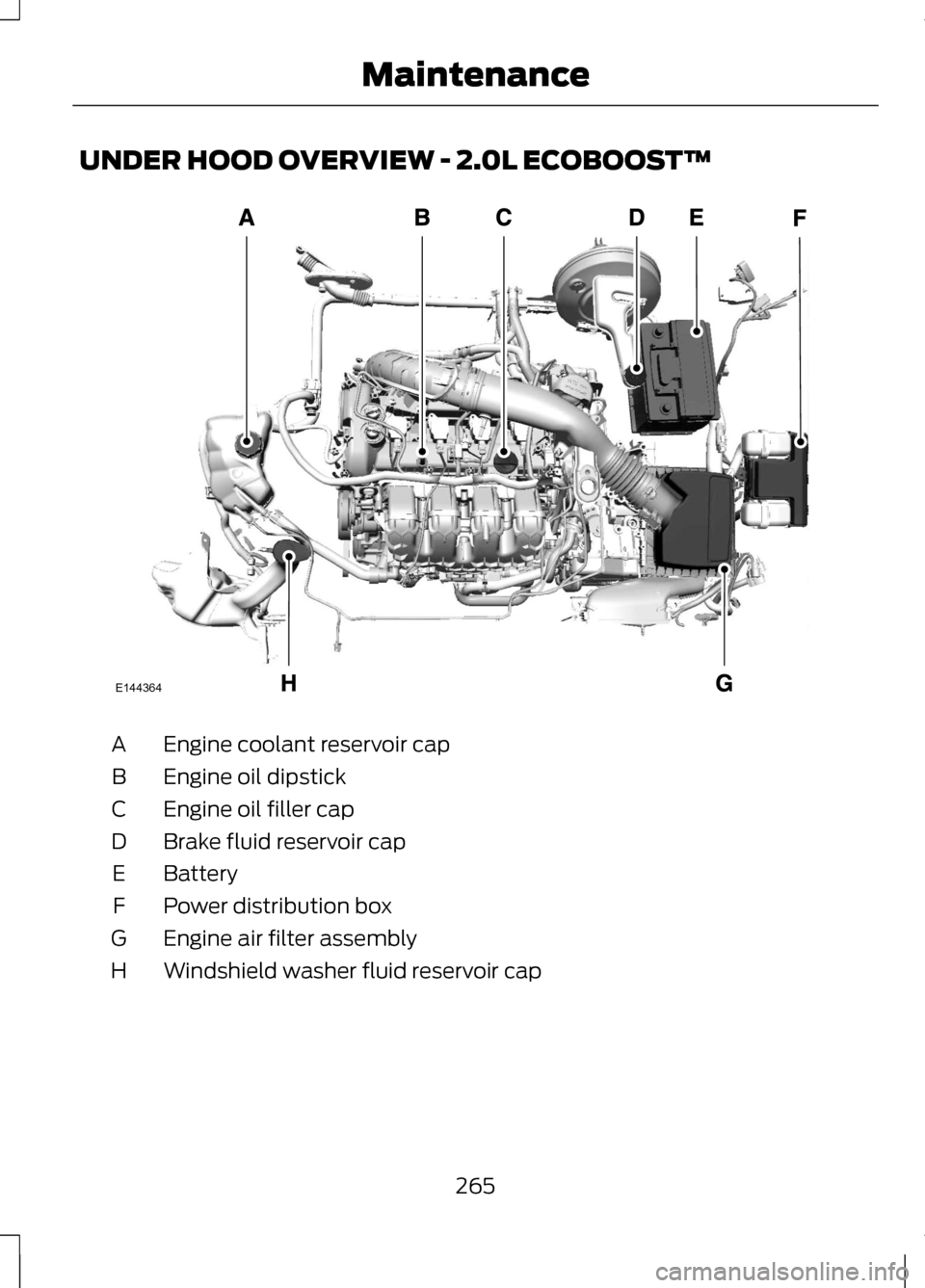
UNDER HOOD OVERVIEW - 2.0L ECOBOOST™
Engine coolant reservoir cap
A
Engine oil dipstick
B
Engine oil filler cap
C
Brake fluid reservoir cap
D
Battery
E
Power distribution box
F
Engine air filter assembly
G
Windshield washer fluid reservoir cap
H
265
MaintenanceE144364
Page 269 of 474
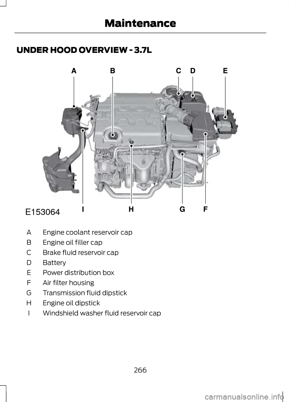
UNDER HOOD OVERVIEW - 3.7L
Engine coolant reservoir cap
A
Engine oil filler cap
B
Brake fluid reservoir cap
C
Battery
D
Power distribution box
E
Air filter housing
F
Transmission fluid dipstick
G
Engine oil dipstick
H
Windshield washer fluid reservoir cap
I
266
MaintenanceE153064
Page 271 of 474
Only use oils certified for gasoline
engines by the American Petroleum
Institute (API). An oil with this
trademark symbol conforms to the
current engine and emission system
protection standards and fuel
economy requirements of the
International Lubricants Specification
Advisory Council (ILSAC), comprised
of U.S. and Japanese automobile
manufacturers.
1. Remove the filler cap.
2.
Add engine oil that meets the Ford
specifications. See Capacities
and Specifications (page 325).
3. Replace the filler cap. Turn it until you feel a strong resistance.
Resetting the Oil Life
Monitoring System
Note: Reset the oil life monitoring only
after an oil change.
1. Turn the ignition key to the on position. Do not start the engine.
For vehicles with push-button
start, press and hold the start
button for two seconds without
pressing the brake pedal. Do not
attempt to start the engine.
2. Press both the accelerator and brake pedals at the same time.
3. Keep both pedals fully pressed.
4. After three seconds, the Service: Oil reset in prog. message will be
displayed.
5. After 25 seconds, the Service: Oil reset complete message will be
displayed. 6.
Release both the accelerator and
brake pedals.
7. The Service: Oil reset complete message will no longer be
displayed.
8. Rotate the key to the off position.
For vehicles with push-button
start, press the start button to turn
the vehicle off completely.
ENGINE COOLANT CHECK -
2.0L ECOBOOST™/3.7L
Checking the Engine Coolant
When the engine is cold, check the
concentration and level of the engine
coolant at the intervals listed in the
scheduled maintenance information.
See Scheduled Maintenance (page
440
).
Note: Make sure that the level is
between the MIN and MAX marks on
the coolant reservoir.
Note: Coolant expands when it is hot.
The level may extend beyond the MAX
mark
Note: If the level is at the MIN mark,
below the MIN mark, or empty, add
coolant immediately. See
Adding
Engine Coolant in this chapter.
The coolant concentration should be
maintained within 48% to 50%,
which equates to a freeze point
between -30 F degrees (-34 C) and
-34 F (-37 C).
268
Maintenance
Page 274 of 474
What you Should Know About
Fail-Safe Cooling
If the engine coolant supply is
depleted, this feature allows the
vehicle to be driven temporarily before
incremental component damage is
incurred. The
“fail-safe” distance
depends on ambient temperatures,
vehicle load and terrain.
How Fail-Safe Cooling Works
If the engine begins to overheat, the
engine coolant temperature gauge
will move to the red (hot) area and: The coolant temperature
warning light will illuminate.
The service engine soon
indicator will illuminate.
If the engine reaches a preset
over-temperature condition, the
engine will automatically switch to
alternating cylinder operation. Each
disabled cylinder acts as an air pump
and cools the engine.
When this occurs the vehicle will still
operate. However:
• The engine power will be limited.
• The air conditioning system will be
disabled.
Continued operation will increase the
engine temperature and the engine
will completely shut down, causing
steering and braking effort to increase. Once the engine temperature cools,
the engine can be re-started. Take
your vehicle to an authorized dealer
as soon as possible to minimize
engine damage.
When Fail-Safe Mode Is Activated WARNINGS
Fail-safe mode is for use during
emergencies only. Operate the
vehicle in fail-safe mode only as long
as necessary to bring the vehicle to
rest in a safe location and seek
immediate repairs. When in fail-safe
mode, the vehicle will have limited
power, will not be able to maintain
high-speed operation, and may
completely shut down without
warning, potentially losing engine
power, power steering assist, and
power brake assist, which may
increase the possibility of a crash
resulting in serious injury. Never remove the coolant
reservoir cap while the engine is
running or hot. You have limited engine power when
in the fail-safe mode, so drive the
vehicle with caution. The vehicle will
not be able to maintain high-speed
operation and the engine will run
rough. Remember that the engine is
capable of completely shutting down
automatically to prevent engine
damage, therefore:
1. Pull off the road as soon as safely
possible and turn off the engine.
2. Arrange for the vehicle to be taken
to an authorized dealer.
271
Maintenance