Specifications LINCOLN MKZ 2017 User Guide
[x] Cancel search | Manufacturer: LINCOLN, Model Year: 2017, Model line: MKZ, Model: LINCOLN MKZ 2017Pages: 564, PDF Size: 5.54 MB
Page 314 of 564
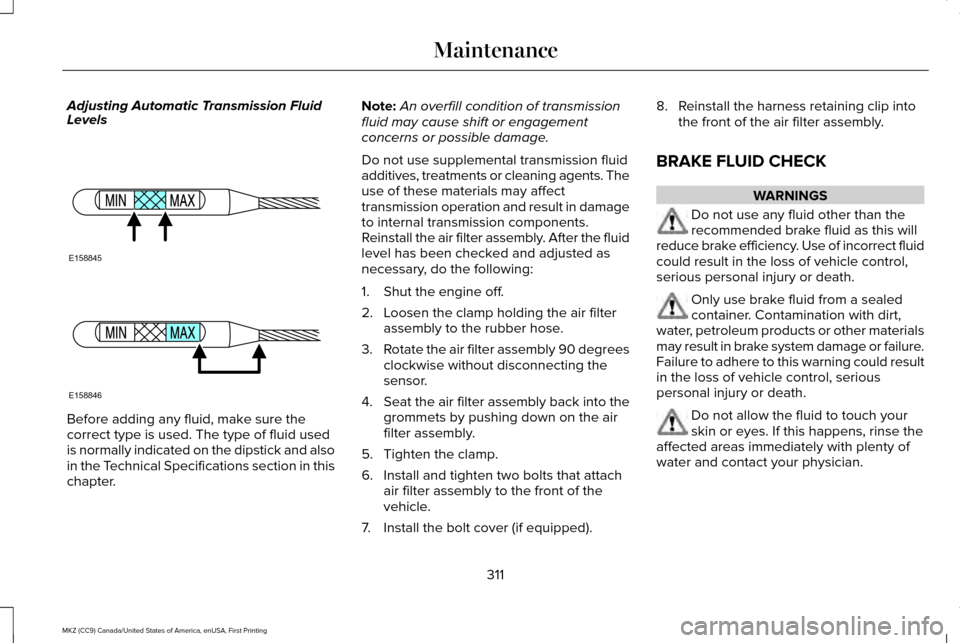
Adjusting Automatic Transmission Fluid
Levels
Before adding any fluid, make sure the
correct type is used. The type of fluid used
is normally indicated on the dipstick and also
in the Technical Specifications section in this
chapter. Note:
An overfill condition of transmission
fluid may cause shift or engagement
concerns or possible damage.
Do not use supplemental transmission fluid
additives, treatments or cleaning agents. The
use of these materials may affect
transmission operation and result in damage
to internal transmission components.
Reinstall the air filter assembly. After the fluid
level has been checked and adjusted as
necessary, do the following:
1. Shut the engine off.
2. Loosen the clamp holding the air filter assembly to the rubber hose.
3. Rotate the air filter assembly 90 degrees
clockwise without disconnecting the
sensor.
4. Seat the air filter assembly back into the
grommets by pushing down on the air
filter assembly.
5. Tighten the clamp.
6. Install and tighten two bolts that attach air filter assembly to the front of the
vehicle.
7. Install the bolt cover (if equipped). 8. Reinstall the harness retaining clip into
the front of the air filter assembly.
BRAKE FLUID CHECK WARNINGS
Do not use any fluid other than the
recommended brake fluid as this will
reduce brake efficiency. Use of incorrect fluid
could result in the loss of vehicle control,
serious personal injury or death. Only use brake fluid from a sealed
container. Contamination with dirt,
water, petroleum products or other materials
may result in brake system damage or failure.
Failure to adhere to this warning could result
in the loss of vehicle control, serious
personal injury or death. Do not allow the fluid to touch your
skin or eyes. If this happens, rinse the
affected areas immediately with plenty of
water and contact your physician.
311
MKZ (CC9) Canada/United States of America, enUSA, First Printing MaintenanceE158845 E158846
Page 315 of 564
WARNINGS
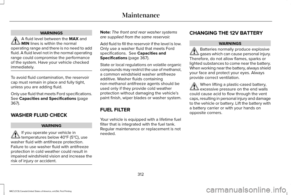
A fluid level between the MAX and
MIN lines is within the normal
operating range and there is no need to add
fluid. A fluid level not in the normal operating
range could compromise the performance
of the system. Have your vehicle checked
immediately. To avoid fluid contamination, the reservoir
cap must remain in place and fully tight,
unless you are adding fluid.
Only use fluid that meets Ford specifications.
See
Capacities and Specifications (page
367).
WASHER FLUID CHECK WARNING
If you operate your vehicle in
temperatures below 40°F (5°C), use
washer fluid with antifreeze protection.
Failure to use washer fluid with antifreeze
protection in cold weather could result in
impaired windshield vision and increase the
risk of injury or accident. Note:
The front and rear washer systems
are supplied from the same reservoir.
Add fluid to fill the reservoir if the level is low.
Only use a washer fluid that meets Ford
specifications.
See Capacities and
Specifications (page 367).
State or local regulations on volatile organic
compounds may restrict the use of methanol,
a common windshield washer antifreeze
additive. Washer fluids containing
non-methanol antifreeze agents should be
used only if they provide cold weather
protection without damaging the vehicle ’s
paint finish, wiper blades or washer system.
FUEL FILTER
Your vehicle is equipped with a lifetime fuel
filter that is integrated with the fuel tank.
Regular maintenance or replacement is not
needed. CHANGING THE 12V BATTERY WARNINGS
Batteries normally produce explosive
gases which can cause personal injury.
Therefore, do not allow flames, sparks or
lighted substances to come near the battery.
When working near the battery, always shield
your face and protect your eyes. Always
provide correct ventilation. When lifting a plastic-cased battery,
excessive pressure on the end walls
could cause acid to flow through the vent
caps, resulting in personal injury and damage
to the vehicle or battery. Lift the battery with
a battery carrier or with your hands on
opposite corners.
312
MKZ (CC9) Canada/United States of America, enUSA, First Printing Maintenance
Page 322 of 564
CHANGING THE ENGINE AIR
FILTER
WARNING
Do not start the engine with the air filter
removed. This can cause damage not
covered by the vehicle Warranty and can
result in serious injury. Only use the specified replacement air filter.
See Capacities and Specifications (page
367).
Change the air filter element at the correct
interval. See Scheduled Maintenance (page
495
).
When changing the engine air filter, do not
allow debris or foreign material to enter the
air induction system. The engine and
turbocharger are susceptible to damage from
even small particles. Note:
Failure to use the correct air filter
element may result in severe engine
damage. Resulting component damage may
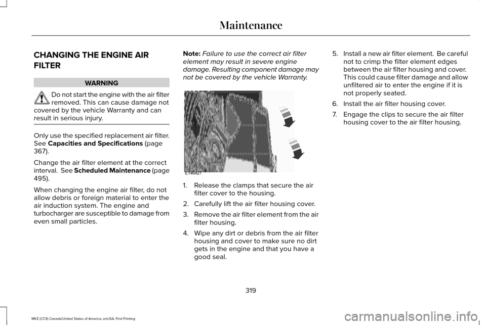
not be covered by the vehicle Warranty. 1. Release the clamps that secure the air
filter cover to the housing.
2. Carefully lift the air filter housing cover.
3. Remove the air filter element from the air
filter housing.
4. Wipe any dirt or debris from the air filter housing and cover to make sure no dirt
gets in the engine and that you have a
good seal. 5.
Install a new air filter element. Be careful
not to crimp the filter element edges
between the air filter housing and cover.
This could cause filter damage and allow
unfiltered air to enter the engine if it is
not properly seated.
6. Install the air filter housing cover.
7. Engage the clips to secure the air filter housing cover to the air filter housing.
319
MKZ (CC9) Canada/United States of America, enUSA, First Printing MaintenanceE146427
Page 365 of 564

16. Remove the jack and fully tighten the
lug nuts in the order shown. See Technical Specifications (page 365).17.
To store the folded wrench on the jack,
engage the bracket of the jack base on
the wrench feature as shown. Swing
the wrench upward and adjust the
height of the jack until the pin engages
the hole. Tighten the hex nut clockwise
by hand until secure. 18. Put the flat tire, jack and lug wrench
away. Make sure the jack is fastened
securely before you drive.
19. Unblock the wheel.
362
MKZ (CC9) Canada/United States of America, enUSA, First Printing Wheels and TiresE176165
Page 368 of 564
TECHNICAL SPECIFICATIONS
Wheel Lug Nut Torque Specifications
WARNING
When a wheel is installed, always remove any corrosion, dirt or foreign \
materials present on the mounting surfaces of the wheel or the
surface of the wheel hub, brake drum or brake disc that contacts the wheel. Make sure that any fasteners that attach the rotor to the
hub are secured so they do not interfere with the mounting surfaces of t\
he wheel. Installing wheels without correct metal-to-metal contact at
the wheel mounting surfaces can cause the wheel nuts to loosen and the w\
heel to come off while your vehicle is in motion, resulting in loss
of control. lb.ft (Nm)
Bolt size
150 lb.ft (204 Nm)
M14 x 1.5
* Torque specifications are for nut and bolt threads free of dirt and rust.\
Use only Ford recommended replacement fasteners.
Retighten the lug nuts to the specified torque within 100 miles (160 kil\
ometers) after any wheel disturbance (such as tire rotation, changing \
a
flat tire, wheel removal).
365
MKZ (CC9) Canada/United States of America, enUSA, First Printing Wheels and Tires
Page 369 of 564
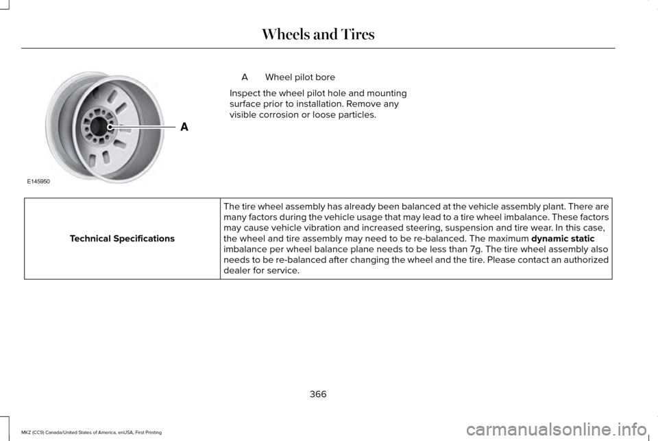
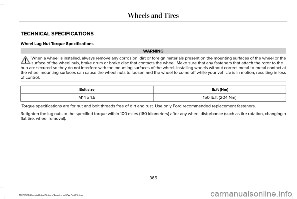
Wheel pilot bore
A
Inspect the wheel pilot hole and mounting
surface prior to installation. Remove any
visible corrosion or loose particles. The tire wheel assembly has already been balanced at the vehicle assembl\
y plant. There are
many factors during the vehicle usage that may lead to a tire wheel imba\
lance. These factors
may cause vehicle vibration and increased steering, suspension and tire \
wear. In this case,
the wheel and tire assembly may need to be re-balanced. The maximum dynamic static
imbalance per wheel balance plane needs to be less than 7g. The tire whe\
el assembly also
needs to be re-balanced after changing the wheel and the tire. Please contact an authorized
dealer for service.
Technical Specifications
366
MKZ (CC9) Canada/United States of America, enUSA, First Printing Wheels and TiresE145950
Page 370 of 564
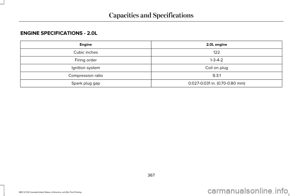
ENGINE SPECIFICATIONS - 2.0L
2.0L engine
Engine
122
Cubic inches
1-3-4-2
Firing order
Coil on plug
Ignition system
9.3:1
Compression ratio
0.027-0.031 in. (0.70-0.80 mm)
Spark plug gap
367
MKZ (CC9) Canada/United States of America, enUSA, First Printing Capacities and Specifications
Page 371 of 564
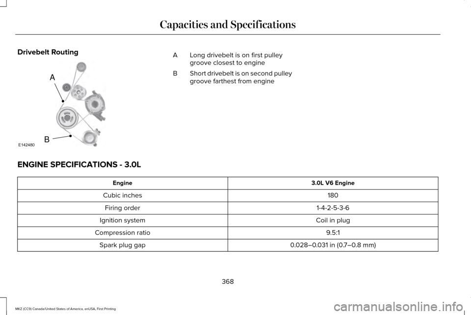
Drivebelt Routing
Long drivebelt is on first pulley
groove closest to engine
A
Short drivebelt is on second pulley
groove farthest from engine
B
ENGINE SPECIFICATIONS - 3.0L 3.0L V6 Engine
Engine
180
Cubic inches
1-4-2-5-3-6
Firing order
Coil in plug
Ignition system
9.5:1
Compression ratio
0.028–0.031 in (0.7–0.8 mm)
Spark plug gap
368
MKZ (CC9) Canada/United States of America, enUSA, First Printing Capacities and SpecificationsA
BE142480
Page 372 of 564
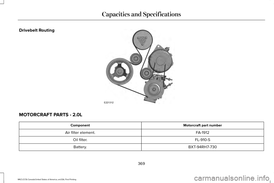
Drivebelt Routing
MOTORCRAFT PARTS - 2.0L
Motorcraft part number
Component
FA-1912
Air filter element.
FL-910-S
Oil filter.
BXT-94RH7-730
Battery.
369
MKZ (CC9) Canada/United States of America, enUSA, First Printing Capacities and SpecificationsE221312
Page 373 of 564
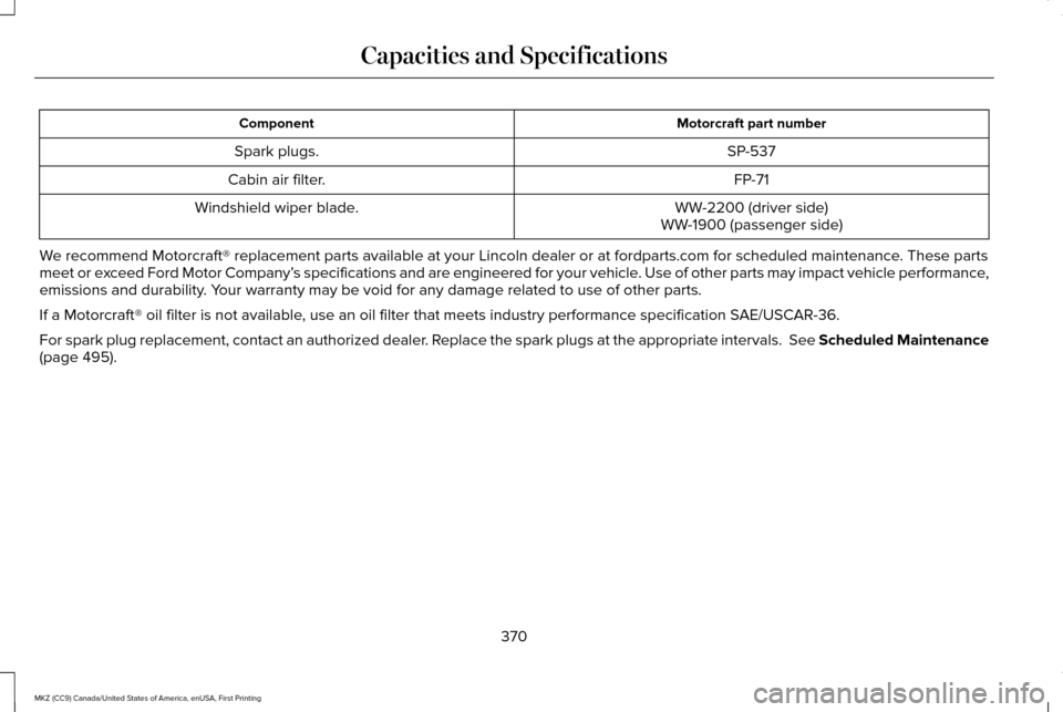
Motorcraft part number
Component
SP-537
Spark plugs.
FP-71
Cabin air filter.
WW-2200 (driver side)
Windshield wiper blade.
WW-1900 (passenger side)
We recommend Motorcraft® replacement parts available at your Lincoln d\
ealer or at fordparts.com for scheduled maintenance. These parts
meet or exceed Ford Motor Company’ s specifications and are engineered for your vehicle. Use of other parts may impact vehicle performance,
emissions and durability. Your warranty may be void for any damage related to use of other parts.
If a Motorcraft® oil filter is not available, use an oil filter that meets industry performance specification SAE/USCAR-36.
For spark plug replacement, contact an authorized dealer. Replace the spark plugs at the appropriate intervals. See Scheduled Maintenance
(page 495).
370
MKZ (CC9) Canada/United States of America, enUSA, First Printing Capacities and Specifications