sensor LINCOLN NAVIGATOR 2015 Owner's Manual
[x] Cancel search | Manufacturer: LINCOLN, Model Year: 2015, Model line: NAVIGATOR, Model: LINCOLN NAVIGATOR 2015Pages: 475, PDF Size: 5.13 MB
Page 199 of 475
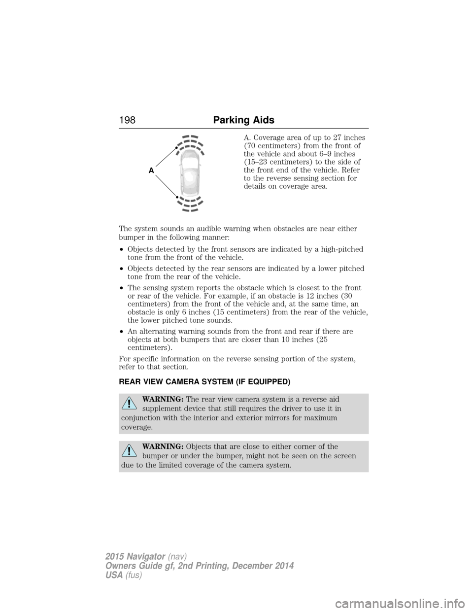
A. Coverage area of up to 27 inches
(70 centimeters) from the front of
the vehicle and about 6–9 inches
(15–23 centimeters) to the side of
the front end of the vehicle. Refer
to the reverse sensing section for
details on coverage area.
The system sounds an audible warning when obstacles are near either
bumper in the following manner:
• Objects detected by the front sensors are indicated by a high-pitched
tone from the front of the vehicle.
• Objects detected by the rear sensors are indicated by a lower pitched
tone from the rear of the vehicle.
• The sensing system reports the obstacle which is closest to the front
or rear of the vehicle. For example, if an obstacle is 12 inches (30
centimeters) from the front of the vehicle and, at the same time, an
obstacle is only 6 inches (15 centimeters) from the rear of the vehicle,
the lower pitched tone sounds.
• An alternating warning sounds from the front and rear if there are
objects at both bumpers that are closer than 10 inches (25
centimeters).
For specific information on the reverse sensing portion of the system,
refer to that section.
REAR VIEW CAMERA SYSTEM (IF EQUIPPED)
WARNING: The rear view camera system is a reverse aid
supplement device that still requires the driver to use it in
conjunction with the interior and exterior mirrors for maximum
coverage.
WARNING: Objects that are close to either corner of the
bumper or under the bumper, might not be seen on the screen
due to the limited coverage of the camera system.
A
198 Parking Aids
2015 Navigator(nav)
Owners Guide gf, 2nd Printing, December 2014
USA (fus)
Page 207 of 475

Using the Systems
BLIS® turns on when the engine is started and the vehicle is driven
forward above 3 mph (5 km/h); it remains on while the transmission is in
D (Drive) or N (Neutral). If shifted out of D (Drive) or N (Neutral), the
system enters CTA mode. Once shifted back into D (Drive), BLIS® turns
back on when the vehicle is driven above 3 mph (5 km/h).
Note:BLIS® does not function in R (Reverse) or P (Park) or provide
any additional warning when a turn signal is on.
CTA detects approaching vehicles from up to 45 feet (14 meters) away
though coverage decreases when the sensors are blocked. Reversing
slowly helps increase the coverage area and effectiveness.
WARNING: To help avoid personal injury, NEVER use the CTA
system as a replacement for using the interior and exterior
mirrors and looking over your shoulder before backing out of a parking
space. CTA is not a replacement for careful driving.
In this first example, the left sensor is only partially obstructed; zone
coverage is nearly maximized.
206 Driving Aids
2015 Navigator(nav)
Owners Guide gf, 2nd Printing, December 2014
USA (fus)
Page 208 of 475
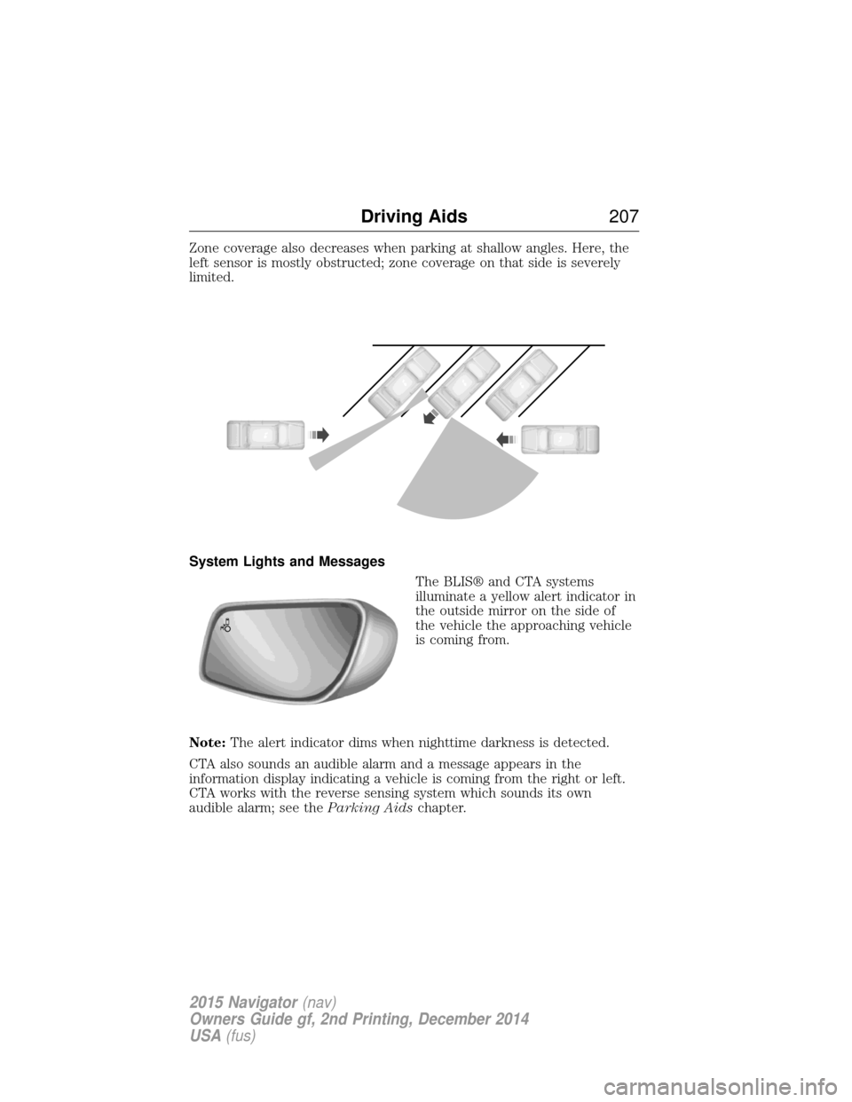
Zone coverage also decreases when parking at shallow angles. Here, the
left sensor is mostly obstructed; zone coverage on that side is severely
limited.
System Lights and MessagesThe BLIS® and CTA systems
illuminate a yellow alert indicator in
the outside mirror on the side of
the vehicle the approaching vehicle
is coming from.
Note: The alert indicator dims when nighttime darkness is detected.
CTA also sounds an audible alarm and a message appears in the
information display indicating a vehicle is coming from the right or left.
CTA works with the reverse sensing system which sounds its own
audible alarm; see the Parking Aidschapter.
Driving Aids 207
2015 Navigator(nav)
Owners Guide gf, 2nd Printing, December 2014
USA (fus)
Page 209 of 475
System Sensors
WARNING:Just prior to the system recognizing a blocked
condition and alerting the driver, the number of missed objects
will increase. To help avoid injuries, NEVER use the BLIS® as a
replacement for using the side and rear view mirrors and looking over
your shoulder before changing lanes. BLIS® is not a replacement for
careful driving.
Note: It is possible to get a blockage warning with no blockage present;
this is rare and known as a false blockage warning. A false blocked
condition either self-corrects or clears after a key cycle.
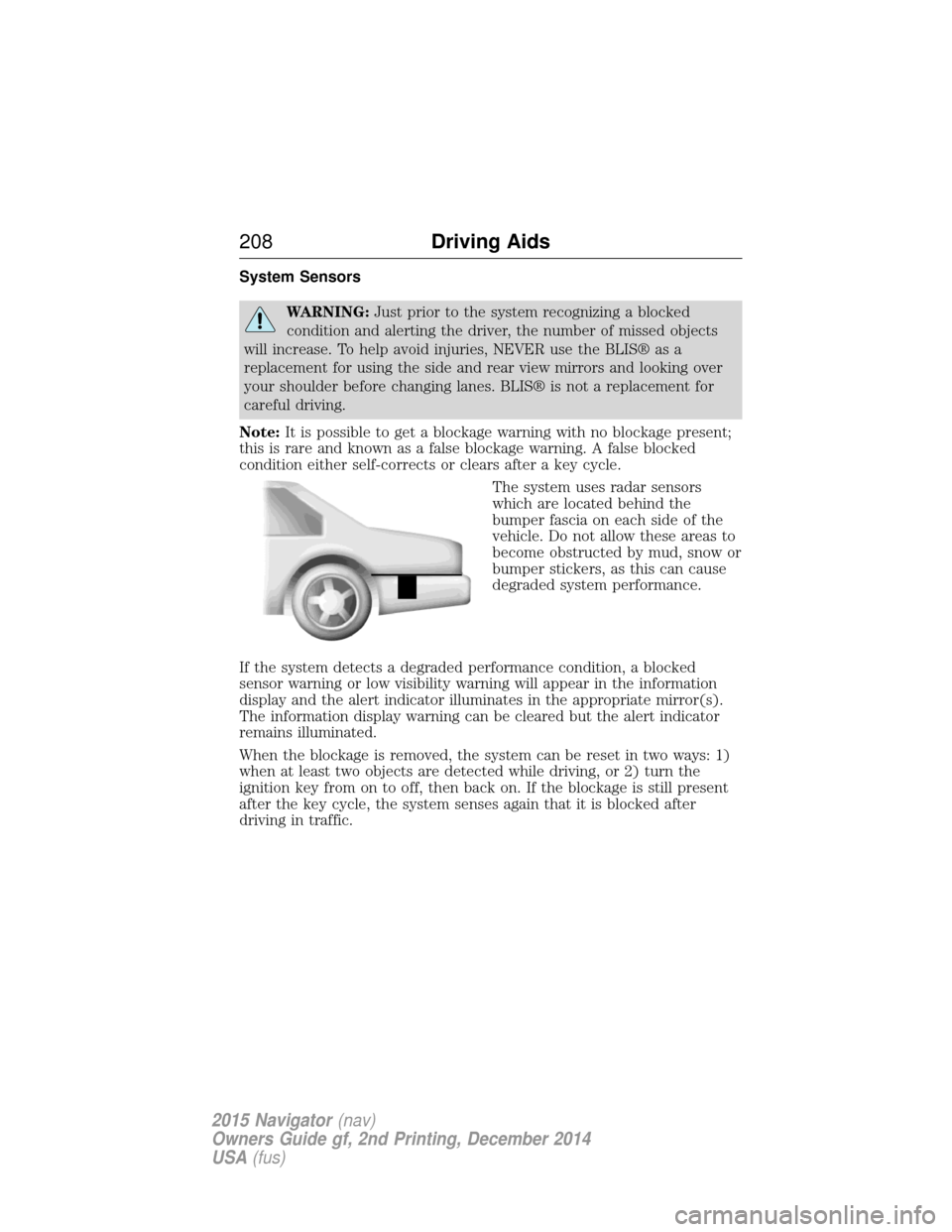
The system uses radar sensors
which are located behind the
bumper fascia on each side of the
vehicle. Do not allow these areas to
become obstructed by mud, snow or
bumper stickers, as this can cause
degraded system performance.
If the system detects a degraded performance condition, a blocked
sensor warning or low visibility warning will appear in the information
display and the alert indicator illuminates in the appropriate mirror(s).
The information display warning can be cleared but the alert indicator
remains illuminated.
When the blockage is removed, the system can be reset in two ways: 1)
when at least two objects are detected while driving, or 2) turn the
ignition key from on to off, then back on. If the blockage is still present
after the key cycle, the system senses again that it is blocked after
driving in traffic.
208 Driving Aids
2015 Navigator(nav)
Owners Guide gf, 2nd Printing, December 2014
USA (fus)
Page 210 of 475
Reasons for messages being displayed
The radar surface is
dirty or obstructed Clean the fascia area in front of the radar or
remove the obstruction.
The radar surface is
not dirty or obstructed Drive normally in traffic for a few minutes to
allow the radar to detect passing vehicles so it
can clear the blocked state.
Heavy rainfall/snowfall
interferes with the
radar signals No action required. The system automatically
resets to an unblocked state once the
rainfall/snowfall rate decreases or stops. Do
not use BLIS® and/or CTA in these conditions.
System Limitations
The BLIS® and CTA systems do have their limitations; situations such as
severe weather conditions or debris build-up on the sensor area may
limit vehicle detection.
The following are other situations that may limit the BLIS®:
• Certain maneuvering of vehicles entering and exiting the blind zone.
• Vehicles passing through the blind zone at very fast rates.
• When several vehicles forming a convoy pass through the blind zone.
The following are other situations that may limit the CTA system:
• Adjacently parked vehicles or objects obstructing the sensors.
• Approaching vehicles passing at speeds greater than 15 mph
(24 km/h).
• Driving in reverse faster than 3 mph (5 km/h).
• Backing out of an angled parking spot.
False Alerts
Note: If you connected a trailer to your vehicle the BLIS® system may
detect the trailer causing a false alert. To avoid false alerts you may want
to turn the BLIS off manually.
There may be certain instances when either the BLIS® or CTA systems
illuminate the alert indicator with no vehicle in the coverage zone; this is
known as a false alert. Some amount of false alerts are normal; they are
temporary and self-correct.
Driving Aids 209
2015 Navigator(nav)
Owners Guide gf, 2nd Printing, December 2014
USA (fus)
Page 211 of 475

System Errors
If either system senses a problem with the left or right sensor, the
BLIS® indicator in the information display will illuminate and remain on.
Also,BLIND SPOT SYSTEM FAULT orCROSS TRAFFIC SYSTEM
FAULT message will appear. When problems that may cause the left or
right indicator not to illuminate, only the information display message
faults appear.
Switching the Systems Off and On
One or both systems can be switched off temporarily by using the
information display control; refer to the Information Displaychapter.
When you switch off the Blind Spot Information System, you will not
receive alerts and the information display will display a system off
message. The yellow alert indicator in the outside mirror will also flash
twice. The system switches back on whenever you switch the ignition on.
You can also have one or both systems switched off permanently at an
authorized dealer. Once switched off, the system can only be switched
back on at an authorized dealer.
STEERING
Electric Power Steering
WARNING: The electric power steering system has diagnostic
checks that continuously monitor the system to ensure proper
operation. When a system error is detected a steering message will
appear in the information display.
WARNING: The electric power steering system has diagnostic
checks that continuously monitor the system to ensure proper
operation of the electronic system. When an electronic error is
detected, a message will be displayed in the information display. If this
happens, stop the vehicle in a safe place, and turn off the engine. After
at least 10 seconds, reset the system by restarting the engine, and
watch the information display for a steering message. If a steering
message returns, or returns while driving, take the vehicle to your
dealer to have it checked.
210 Driving Aids
2015 Navigator(nav)
Owners Guide gf, 2nd Printing, December 2014
USA (fus)
Page 258 of 475
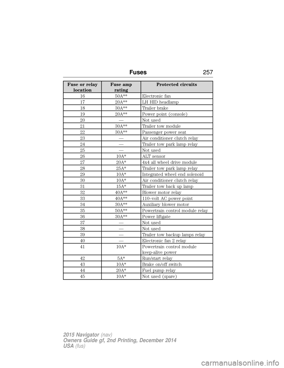
Fuse or relaylocation Fuse amp
rating Protected circuits
16 50A** Electronic fan
17 20A** LH HID headlamp
18 30A** Trailer brake
19 20A** Power point (console)
20 — Not used
21 30A** Trailer tow module
22 30A** Passenger power seat
23 — Air conditioner clutch relay
24 — Trailer tow park lamp relay
25 — Not used
26 10A* ALT sensor
27 20A* 4x4 all wheel drive module
28 25A* Trailer tow park lamp relay
29 10A* Integrated wheel end solenoid
30 10A* Air conditioner clutch relay
31 15A* Trailer tow back up lamp
32 40A** Blower motor relay
33 40A** 110–volt AC power point
34 30A** Auxiliary blower motor
35 50A** Powertrain control module relay
36 30A** Power liftgate
37 — Not used
38 — Not used
39 — Trailer tow backup lamps relay
40 — Electronic fan 2 relay
41 10A* Powertrain control module keep-alive power
42 5A* Run/start relay
43 10A* Brake on/off switch
44 20A* Fuel pump relay
45 10A* Not used (spare)
Fuses 257
2015 Navigator(nav)
Owners Guide gf, 2nd Printing, December 2014
USA (fus)
Page 260 of 475
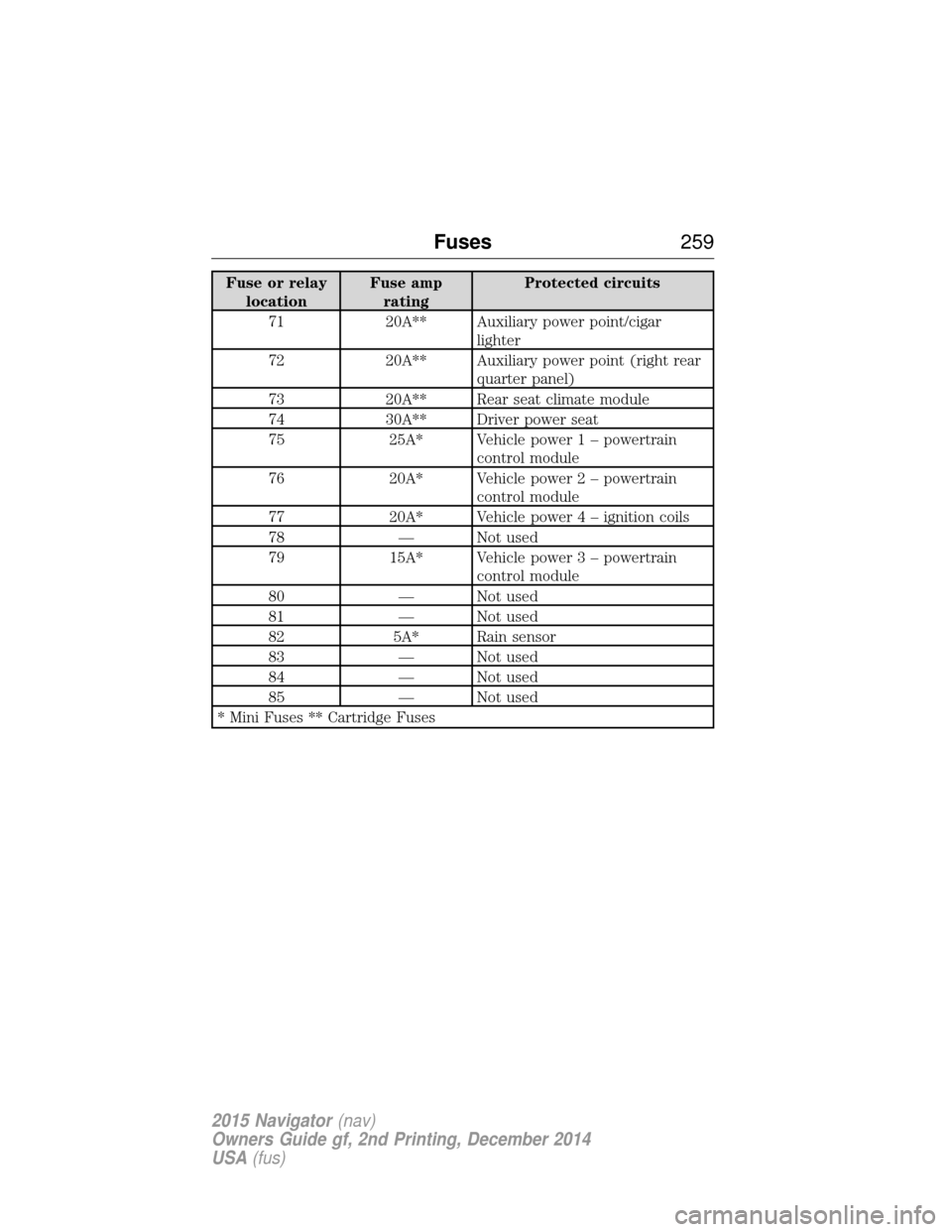
Fuse or relaylocation Fuse amp
rating Protected circuits
71 20A** Auxiliary power point/cigar lighter
72 20A** Auxiliary power point (right rear quarter panel)
73 20A** Rear seat climate module
74 30A** Driver power seat
75 25A* Vehicle power 1 – powertrain control module
76 20A* Vehicle power 2 – powertrain
control module
77 20A* Vehicle powe r4–ignition coils
78 — Not used
79 15A* Vehicle power 3 – powertrain
control module
80 — Not used
81 — Not used
82 5A* Rain sensor
83 — Not used
84 — Not used
85 — Not used
* Mini Fuses ** Cartridge Fuses
Fuses 259
2015 Navigator(nav)
Owners Guide gf, 2nd Printing, December 2014
USA (fus)
Page 278 of 475
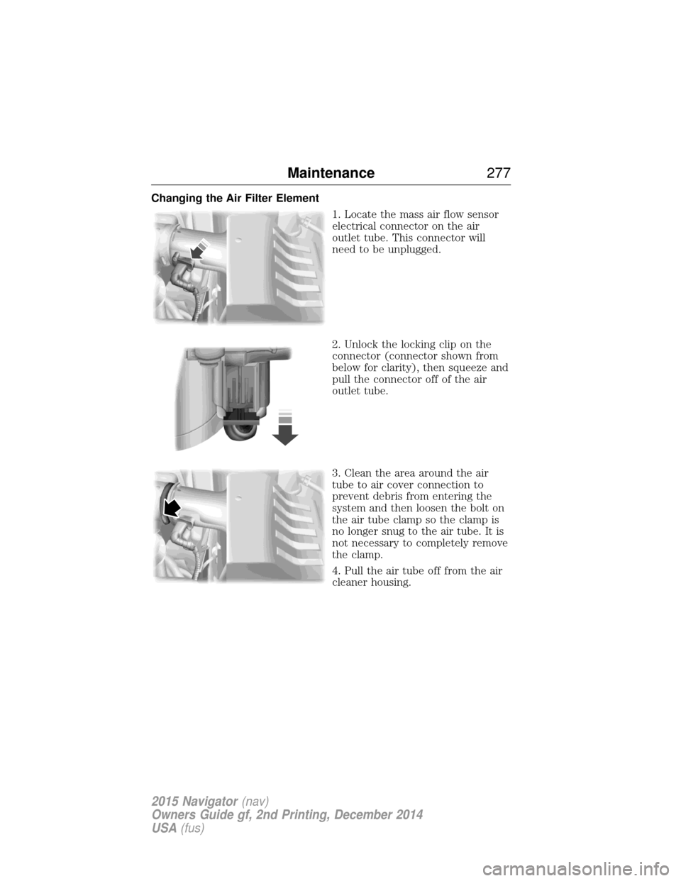
Changing the Air Filter Element1. Locate the mass air flow sensor
electrical connector on the air
outlet tube. This connector will
need to be unplugged.
2. Unlock the locking clip on the
connector (connector shown from
below for clarity), then squeeze and
pull the connector off of the air
outlet tube.
3. Clean the area around the air
tube to air cover connection to
prevent debris from entering the
system and then loosen the bolt on
the air tube clamp so the clamp is
no longer snug to the air tube. It is
not necessary to completely remove
the clamp.
4. Pull the air tube off from the air
cleaner housing.
Maintenance277
2015 Navigator(nav)
Owners Guide gf, 2nd Printing, December 2014
USA (fus)
Page 279 of 475
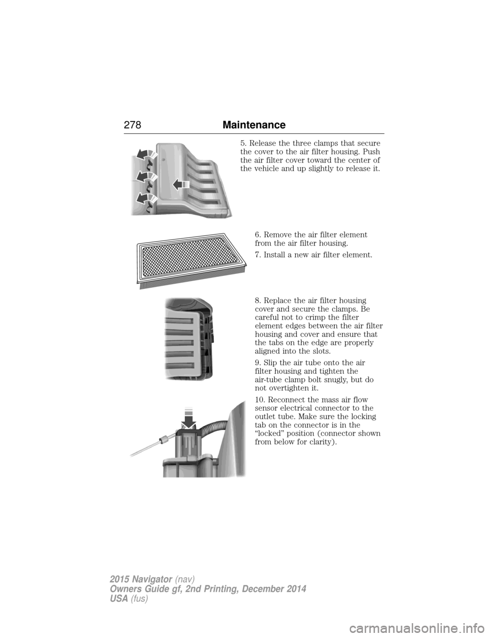
5. Release the three clamps that secure
the cover to the air filter housing. Push
the air filter cover toward the center of
the vehicle and up slightly to release it.6. Remove the air filter element
from the air filter housing.
7. Install a new air filter element.
8. Replace the air filter housing
cover and secure the clamps. Be
careful not to crimp the filter
element edges between the air filter
housing and cover and ensure that
the tabs on the edge are properly
aligned into the slots.
9. Slip the air tube onto the air
filter housing and tighten the
air-tube clamp bolt snugly, but do
not overtighten it.
10. Reconnect the mass air flow
sensor electrical connector to the
outlet tube. Make sure the locking
tab on the connector is in the
“locked” position (connector shown
from below for clarity).
278 Maintenance
2015 Navigator(nav)
Owners Guide gf, 2nd Printing, December 2014
USA (fus)