display LINCOLN NAVIGATOR 2020 Owners Manual
[x] Cancel search | Manufacturer: LINCOLN, Model Year: 2020, Model line: NAVIGATOR, Model: LINCOLN NAVIGATOR 2020Pages: 622, PDF Size: 6.47 MB
Page 299 of 622
Time Gap
Distance Gap
Graphics
Sensitivity
Speed
>0.9sec
>82 ft (25 m)
Grey
Normal
62 mph (100 km/h)
0.6sec — 0.9sec
56–82 ft (17–25 m)
Yellow
Normal
62 mph (100 km/h)
<0.6sec
<
56 ft (17 m)
Red
Normal
62 mph (100 km/h)
Adjusting the Pre-Collision Assist
Settings
You can adjust the following settings by
using the information display controls.
See
General Information (page 133).
• You can adjust the Alert and Distance
Alert sensitivity to one of three settings.
• You can switch the Distance Indication
and Alert function on or off.
• If required, you can switch Active Braking
on or off.
Note: Active braking automatically turns on
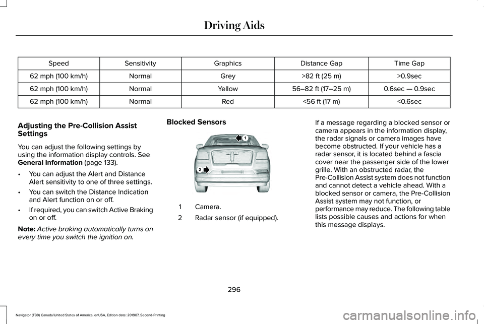
every time you switch the ignition on. Blocked Sensors
Camera.
1
Radar sensor (if equipped).
2 If a message regarding a blocked sensor or
camera appears in the information display,
the radar signals or camera images have
become obstructed. If your vehicle has a
radar sensor, it is located behind a fascia
cover near the passenger side of the lower
grille. With an obstructed radar, the
Pre-Collision Assist system does not function
and cannot detect a vehicle ahead. With a
blocked sensor or camera, the Pre-Collision
Assist system may not function, or
performance may reduce. The following table
lists possible causes and actions for when
this message displays.
296
Navigator (TB9) Canada/United States of America, enUSA, Edition date: 201907, Second-Printing Driving AidsE253503
Page 300 of 622
Camera Troubleshooting
Action
Cause
Clean the outside of the windshield in front of the camera.
The windshield in front of the camera is dirty or obstructed in some
way.
Wait a short time. It may take several minutes for the camera to detectthat there is no obstruction.
The windshield in front of the camera is clean but the message remains
in the display.
297
Navigator (TB9) Canada/United States of America, enUSA, Edition date: 201907, Second-Printing Driving Aids
Page 301 of 622
Radar Troubleshooting (If Equipped)
Action
Cause
The surface of the radar in the grille is clean but the message remainsin the display.
The surface of the radar in the grille is dirty or obstructed in some
way.
Wait a short time. It may take several minutes for the radar to detectthat there is no obstruction.
The surface of the radar in the grille is clean but the message remains
in the display.
The Pre-Collision Assist system is disabled. Pre-Collision Assist should\
automatically reactivate a short time after the weather conditions improve.
Heavy rain, spray, snow, or fog is interfering with the radar signals.
The Pre-Collision Assist system is disabled. Pre-Collision Assist should\
automatically reactivate a short time after the weather conditions improve.
Swirling water, or snow or ice on the surface of the road may interfere
with the radar signals.
Contact an authorized dealer to have the radar checked for propercoverage and operation.
Radar is out of alignment due to a front-end impact.
Note: Proper system operation requires a
clear view of the road by the camera. Have
any windshield damage in the camera's field
of view repaired. Note:
If something hits the front end of your
vehicle or damage occurs, the radar sensing
zone may change. This could cause missed
or false vehicle detections. Contact an
authorized dealer to have the radar checked
for proper coverage and operation.
298
Navigator (TB9) Canada/United States of America, enUSA, Edition date: 201907, Second-Printing Driving Aids
Page 302 of 622
Note:
If your vehicle detects excessive heat
at the camera or a potential misalignment
condition, a message may display in the
information display indicating temporary
sensor unavailability. When operational
conditions are correct, the message
deactivates. For example, when the ambient
temperature around the sensor decreases
or the sensor automatically recalibrates
successfully.
DRIVE MODE CONTROL
Lincoln Drive Modes
Lincoln Drive Modes deliver a driving
experience through a suite of sophisticated
electronic vehicle systems. These systems
optimize steering, handling and powertrain
response. You can control performance
settings for multiple systems from this single
location.
Changing the drive mode automatically
changes the functionality of the following
systems: •
Electronically power-assisted steering
system adjusts steering effort and feel
based on the mode you select. See
Steering (page 293).
• Electronic stability control and traction
control maintain your vehicle control in
adverse conditions or high performance
driving. See Stability Control (page
244).
• Electronic throttle control enhances the
powertrain response to your inputs.
• Transmission controls optimize with shift
schedules tuned to each mode.
• Driveline settings optimize for each
mode.
Using the System
The system automatically tailors your vehicle
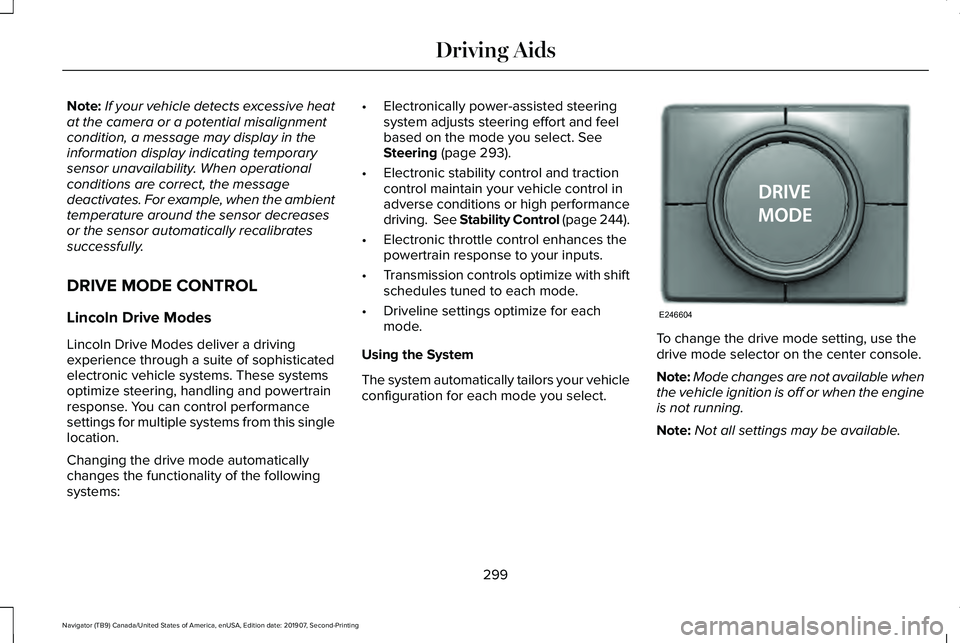
configuration for each mode you select. To change the drive mode setting, use the
drive mode selector on the center console.
Note:
Mode changes are not available when
the vehicle ignition is off or when the engine
is not running.
Note: Not all settings may be available.
299
Navigator (TB9) Canada/United States of America, enUSA, Edition date: 201907, Second-Printing Driving AidsE246604
Page 316 of 622
You have to set up each trailer you use with
your vehicle. You must accurately follow the
setup process to make sure you correctly
place the sticker.
Contact your dealership if you need
assistance in setting up your trailer.
Setting Up Pro Trailer Backup Assist
Note:
Once you enter a trailer's information,
the system stores it for easy recall. You can
add a maximum of 10 trailers to the system.
Step 1: Position your Vehicle and Trailer
Hitch the conventional trailer to your vehicle.
See Essential Towing Checks (page 326).
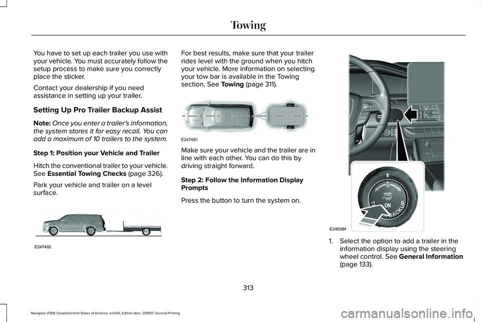
Park your vehicle and trailer on a level
surface. For best results, make sure that your trailer
rides level with the ground when you hitch
your vehicle. More information on selecting
your tow bar is available in the Towing
section.
See Towing (page 311).
Make sure your vehicle and the trailer are in
line with each other. You can do this by
driving straight forward.
Step 2: Follow the Information Display
Prompts
Press the button to turn the system on.
1. Select the option to add a trailer in the
information display using the steering
wheel control.
See General Information
(page 133).
313
Navigator (TB9) Canada/United States of America, enUSA, Edition date: 201907, Second-Printing TowingE247482 E247481 E246984
Page 317 of 622
2. Add a personalized name for the trailer
using the screen prompts. Use the down
arrow to scroll to the desired letter and
then press the toggle switch to advance
to the next letter. Press OK to continue.
3. Select the type of trailer brake system for
the trailer you are adding.
4. Select the brake effort level for the trailer.
Note: The default option is low. We
recommend this for most trailers. If the
trailer's brakes require more initial voltage,
or if you prefer more aggressive braking,
then select the other options as required.
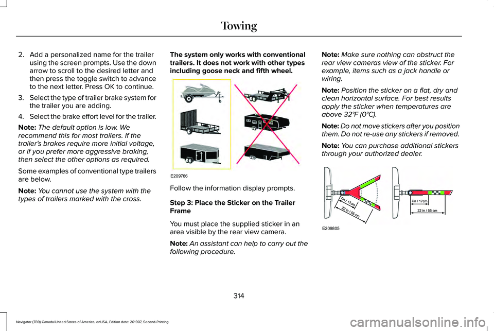
Some examples of conventional type trailers
are below.
Note: You cannot use the system with the
types of trailers marked with the cross. The system only works with conventional
trailers. It does not work with other types
including goose neck and fifth wheel.
Follow the information display prompts.
Step 3: Place the Sticker on the Trailer
Frame
You must place the supplied sticker in an
area visible by the rear view camera.
Note:
An assistant can help to carry out the
following procedure. Note:
Make sure nothing can obstruct the
rear view cameras view of the sticker. For
example, items such as a jack handle or
wiring.
Note: Position the sticker on a flat, dry and
clean horizontal surface. For best results
apply the sticker when temperatures are
above 32°F (0°C).
Note: Do not move stickers after you position
them. Do not re-use any stickers if removed.
Note: You can purchase additional stickers
through your authorized dealer. 314
Navigator (TB9) Canada/United States of America, enUSA, Edition date: 201907, Second-Printing TowingE209766 E209805
Page 318 of 622
Use the supplied measurement card, a tape
measure and pen to carefully mark the area
where to attach the sticker (supplied in the
back cover pocket of your quick start guide).
Make sure the whole sticker is within the
zone between the two arcs or distance
markers on the diagram, and is also visible
in the rear view camera display.
Step 4: Take Measurements
After you correctly place the sticker on the
trailer, you must take some key
measurements.
Note:
You must take accurate
measurements for the system to operate
properly.
Note: When rounding in inches, round
upward if the measured length is a quarter
inch or greater. Round downward if the
measured length is less than a quarter inch.
For example 12.25 in (31.11 cm) would be
rounded up to 12.50 in (31.75 cm). 12.13 in
(30.8 cm) would be rounded down to 12.00 in
(30.48 cm)
. Note:
When rounding in centimeters, round
to the nearest whole centimeter. If the
measurement is less than
0.2 in (0.5 cm)
round downward. If the measurement is
more than or equal to
0.2 in (0.5 cm) round
upward. For example, 11.9 in (30.3 cm) would
be rounded down to 11.8 in (30 cm). 12.0 in
(30.5 cm) would be rounded up to 12.2 in
(31 cm).
Note: Use consistent metric or imperial units
as required by your country or vehicle.
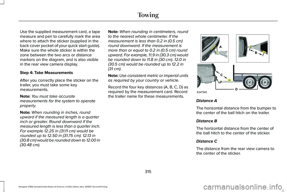
Record the four key distances (A, B, C, D) as
required by the measurement card. Record
the trailer name for these measurements. Distance A
The horizontal distance from the bumper to
the center of the ball hitch on the trailer.
Distance B
The horizontal distance from the center of
the ball hitch to the center of the sticker.
Distance C
The distance from the rear view camera to
the center of the sticker.
315
Navigator (TB9) Canada/United States of America, enUSA, Edition date: 201907, Second-Printing TowingE247545
Page 319 of 622
Distance D
The horizontal distance from the bumper to
the center of the trailer axle (single axle
trailers), or the center of the axles (trailers
with dual axles or more).
Note:
If the distance ends in anything less
than one half of an inch, round down to the
current whole inch. If a distance ends in one
half or greater of an inch, round up to the
next whole inch. For example, 12.3 in
(31.12 cm) would be rounded down to 12 in
(30.48 cm). 12.5 in (31.75 cm) would be
rounded up to 13 in (33 cm).
Step 5: Enter Measurements Using the
Information Display
Using the recorded measurements, enter the
required data into the system. Follow the on
screen prompts to enter each of the
measurements taken in step 4. When all four
distances have been entered, a confirmation
display will appear. Check the values are
correct before proceeding, or go back to
change any if required. Step 6: Confirming the Sticker Location
Check the rear view camera display to see
if the sticker is identified by the system and
marked with a red circle.
Confirm that the red circle is correctly located
over the sticker image in the display. The on
screen prompt will ask you to confirm this.
Note:
If the system cannot locate the sticker
try cleaning the camera lens, and also make
sure the sticker is within the green zone as
indicated in step 3.
Calibrating the System
To complete setup, drive your vehicle
straight forward between 4 mph (6 km/h) and
24 mph (39 km/h)
following the on screen
prompt.
Note: Check your measurements to make
sure you measured from the correct points.
Note: If you move the steering wheel during
this procedure, the calibration pauses.
Note: We recommend that you do not do
this at night. A message will be displayed during
calibration and after calibration is complete.
Using Pro Trailer Backup Assist
To use the system press the button and
select the required trailer from the display.
316
Navigator (TB9) Canada/United States of America, enUSA, Edition date: 201907, Second-Printing Towing
Page 320 of 622
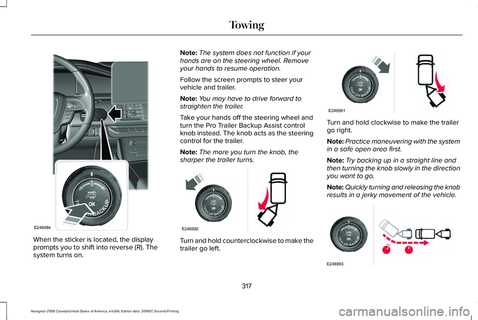
When the sticker is located, the display
prompts you to shift into reverse (R). The
system turns on. Note:
The system does not function if your
hands are on the steering wheel. Remove
your hands to resume operation.
Follow the screen prompts to steer your
vehicle and trailer.
Note: You may have to drive forward to
straighten the trailer.
Take your hands off the steering wheel and
turn the Pro Trailer Backup Assist control
knob instead. The knob acts as the steering
control for the trailer.
Note: The more you turn the knob, the
sharper the trailer turns. Turn and hold counterclockwise to make the
trailer go left. Turn and hold clockwise to make the trailer
go right.
Note:
Practice maneuvering with the system
in a safe open area first.
Note: Try backing up in a straight line and
then turning the knob slowly in the direction
you want to go.
Note: Quickly turning and releasing the knob
results in a jerky movement of the vehicle. 317
Navigator (TB9) Canada/United States of America, enUSA, Edition date: 201907, Second-Printing TowingE246984 E246992 E246991 E246993
Page 322 of 622
Measurement B has reached maximum or
minimum value:
•
Make sure that the sticker placement
instruction in step 3 of the setup has
been followed. Stickers placed outside
the allowed zone will adversely affect the
system performance and could cause
improper feature function.
• Make sure that the measurement being
made is the horizontal distance only from
center of sticker to the hitch ball center.
A straight line distance that includes any
vertical rise or drop will increase the
measurement and cause an inaccurate
value to be entered into the system. See
step 4 of the setup for additional
measurement instructions.
Measurement C has reached maximum or
minimum value:
• Make sure that the sticker placement
instructions in step 3 of the setup have
been followed. Stickers placed outside
the allowed zone will adversely affect the
system performance and could cause
improper feature function. If you have
met all the criteria for sticker placement
and you see this message this sticker is either too far below or too close to the
camera to properly recognize the sticker.
In order for the system to operate
correctly the sticker height must be
lowered if you receive the minimum
warning or the sticker height must be
raised if you receive the maximum
warning.
• Only one sticker can be placed on the
trailer for correct system function. The
previous sticker must be removed or
covered so only one sticker is visible to
the camera.
• Measurement B and C must be measured
again if a new sticker is placed on the
trailer.
Measurement D has reached maximum or
minimum value:
• Make sure that the measurement being
made is the horizontal distance only from
the bumper to the center of the single
axle or the center of all the axles on the
trailer. See step 4 of the setup for
additional measurement instructions. The
TBA system does not support trailer
lengths outside the range allowed by the
information display. System is circling something beside the
sticker or system cannot find the sticker:
•
Make sure the rear camera is clean and
the sticker is clearly visible in the camera
image. Clean the camera and sticker if
necessary.
• The camera system uses the entered
measurements to help locate the sticker.
Inaccurate sticker measurements will
degrade the system ’s ability to locate the
sticker. Verify the measurements entered
into the system are accurate.
• Remove the incorrectly circled label or
decal if possible.
• If you cannot resolve the issue a new
sticker location should be tried. The
sticker location must still meet the
requirements noted in step 3 of the setup
instructions. Only one sticker can be
placed on the trailer for correct system
function. The previous sticker must be
removed or covered so only one sticker
is visible to the camera.
319
Navigator (TB9) Canada/United States of America, enUSA, Edition date: 201907, Second-Printing Towing