brake sensor LINCOLN TOWN CAR 2000 Owners Manual
[x] Cancel search | Manufacturer: LINCOLN, Model Year: 2000, Model line: TOWN CAR, Model: LINCOLN TOWN CAR 2000Pages: 224, PDF Size: 1.73 MB
Page 121 of 224

your vehicle. It is especially useful on slippery and/or hilly road surfaces.
The system operates by detecting and controlling wheel spin. The system
borrows many of the electronic and mechanical elements already present
in the anti-lock braking system (ABS).
Wheel-speed sensors allow excess rear wheel spin to be detected by the
Traction Controlyportion of the ABS computer. Any excessive wheel
spin is controlled by automatically applying and releasing the rear brakes
in conjunction with engine torque reductions. Engine torque reduction is
realized via the fully electronic spark and fuel injection systems. This
process is very sensitive to driving conditions and very fast acting. The
rear wheels ªsearchº for optimum traction several times a second and
adjustments are made accordingly.
The Traction Controlysystem will allow your vehicle to make better use
of available traction on slippery surfaces. The system is a driver aid
which makes your vehicle easier to handle primarily on snow and ice
covered roads.
During Traction Controlyoperation you may hear an electric motor type
of sound coming from the engine compartment and the engine will not
ªrev-upº when you push further on the accelerator. This is normal
system behavior.
If you should become stuck in snow or ice or on a very slippery road
surface, try switching the Traction Controlysystem off. This may allow
excess wheel spin to ªdigº the vehicle out and enable a successful
ªrockingº maneuver.
If the Traction Controlysystem is cycled excessively, the brake portion
of the system will shut down to prevent the rear brakes from
overheating. A limited Traction Controlyfunction using only engine
torque reduction will still control wheels from over-spinning. When the
rear brakes have cooled down, the system will again function normally.
Anti-lock braking is not affected by this condition and will function
normally during the cool down period.
Traction control switch
The traction control switch is located on the left side of the glove
compartment. The traction control system defaults to ON when the
ignition key is turned from OFF to RUN.
Driving
121
Page 136 of 224

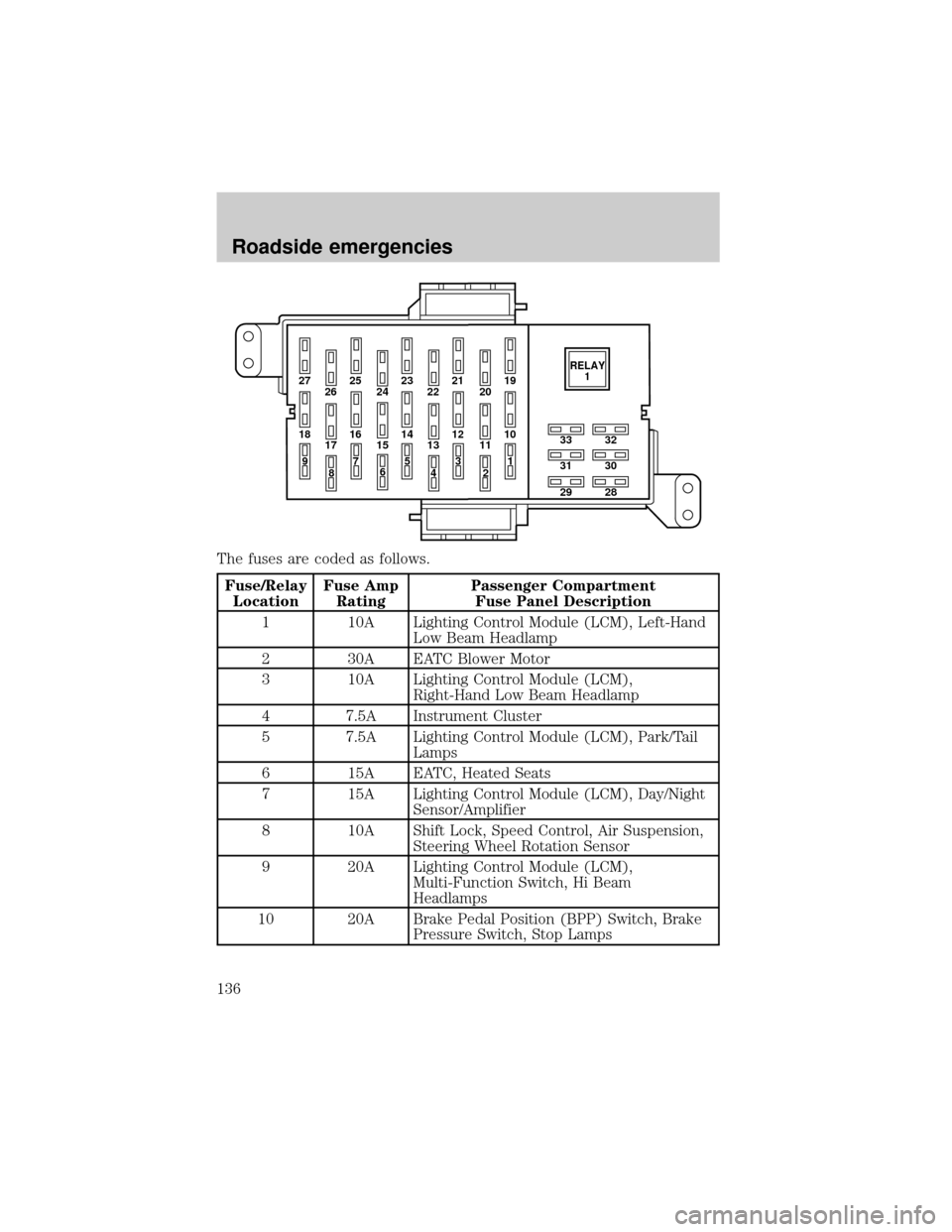
The fuses are coded as follows.
Fuse/Relay
LocationFuse Amp
RatingPassenger Compartment
Fuse Panel Description
1 10A Lighting Control Module (LCM), Left-Hand
Low Beam Headlamp
2 30A EATC Blower Motor
3 10A Lighting Control Module (LCM),
Right-Hand Low Beam Headlamp
4 7.5A Instrument Cluster
5 7.5A Lighting Control Module (LCM), Park/Tail
Lamps
6 15A EATC, Heated Seats
7 15A Lighting Control Module (LCM), Day/Night
Sensor/Amplifier
8 10A Shift Lock, Speed Control, Air Suspension,
Steering Wheel Rotation Sensor
9 20A Lighting Control Module (LCM),
Multi-Function Switch, Hi Beam
Headlamps
10 20A Brake Pedal Position (BPP) Switch, Brake
Pressure Switch, Stop Lamps
27 25
26 2423 21
2219
20
18 16
17 1514 12
1310
33
31
2932
30
28 11
97
8653
41
2RELAY
1
Roadside emergencies
136
Page 137 of 224

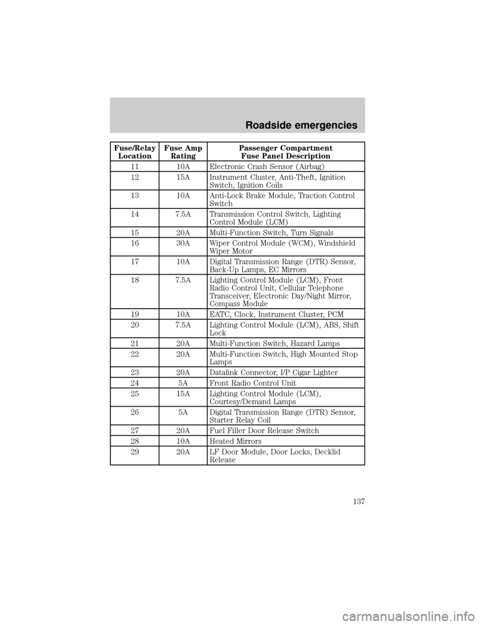
Fuse/Relay
LocationFuse Amp
RatingPassenger Compartment
Fuse Panel Description
11 10A Electronic Crash Sensor (Airbag)
12 15A Instrument Cluster, Anti-Theft, Ignition
Switch, Ignition Coils
13 10A Anti-Lock Brake Module, Traction Control
Switch
14 7.5A Transmission Control Switch, Lighting
Control Module (LCM)
15 20A Multi-Function Switch, Turn Signals
16 30A Wiper Control Module (WCM), Windshield
Wiper Motor
17 10A Digital Transmission Range (DTR) Sensor,
Back-Up Lamps, EC Mirrors
18 7.5A Lighting Control Module (LCM), Front
Radio Control Unit, Cellular Telephone
Transceiver, Electronic Day/Night Mirror,
Compass Module
19 10A EATC, Clock, Instrument Cluster, PCM
20 7.5A Lighting Control Module (LCM), ABS, Shift
Lock
21 20A Multi-Function Switch, Hazard Lamps
22 20A Multi-Function Switch, High Mounted Stop
Lamps
23 20A Datalink Connector, I/P Cigar Lighter
24 5A Front Radio Control Unit
25 15A Lighting Control Module (LCM),
Courtesy/Demand Lamps
26 5A Digital Transmission Range (DTR) Sensor,
Starter Relay Coil
27 20A Fuel Filler Door Release Switch
28 10A Heated Mirrors
29 20A LF Door Module, Door Locks, Decklid
Release
Roadside emergencies
137
Page 140 of 224

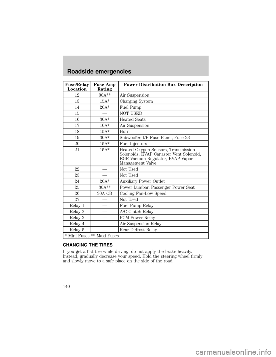
Fuse/Relay
LocationFuse Amp
RatingPower Distribution Box Description
12 30A** Air Suspension
13 15A* Charging System
14 20A* Fuel Pump
15 Ð NOT USED
16 30A* Heated Seats
17 10A* Air Suspension
18 15A* Horn
19 30A* Subwoofer, I/P Fuse Panel, Fuse 33
20 15A* Fuel Injectors
21 15A* Heated Oxygen Sensors, Transmission
Solenoids, EVAP Canaster Vent Solenoid,
EGR Vacuum Regulator, EVAP Vapor
Management Valve
22 Ð Not Used
23 Ð Not Used
24 20A* Auxiliary Power Outlet
25 30A** Power Lumbar, Passenger Power Seat
26 30A CB Cooling Fan-Low Speed
27 Ð Not Used
Relay 1 Ð Fuel Pump Relay
Relay 2 Ð A/C Clutch Relay
Relay 3 Ð PCM Power Relay
Relay 4 Ð Air Suspension Relay
Relay 5 Ð Rear Defrost Relay
* Mini Fuses ** Maxi Fuses
CHANGING THE TIRES
If you get a flat tire while driving, do not apply the brake heavily.
Instead, gradually decrease your speed. Hold the steering wheel firmly
and slowly move to a safe place on the side of the road.
Roadside emergencies
140