oil LINCOLN TOWN CAR 2001 Owners Manual
[x] Cancel search | Manufacturer: LINCOLN, Model Year: 2001, Model line: TOWN CAR, Model: LINCOLN TOWN CAR 2001Pages: 240, PDF Size: 1.92 MB
Page 5 of 240
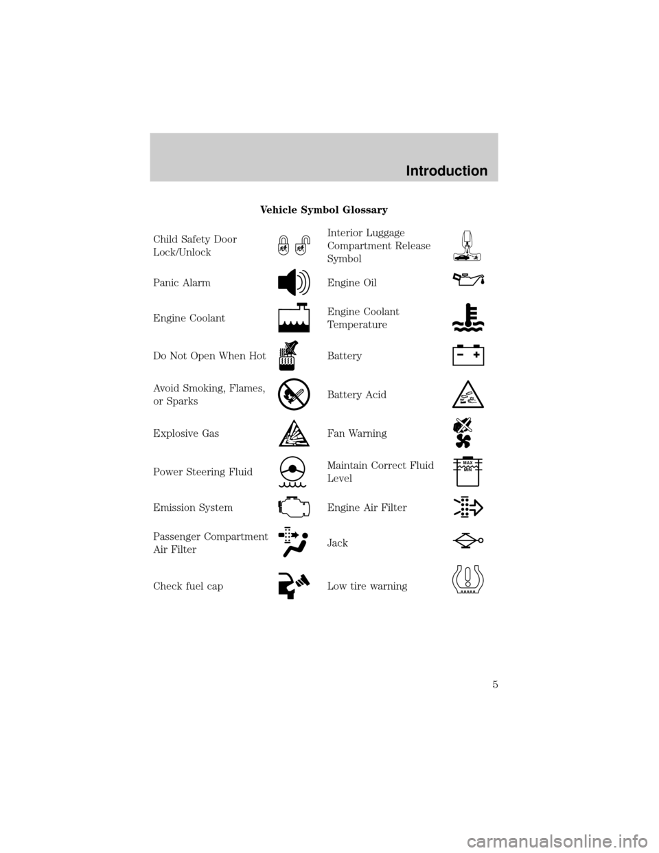
Vehicle Symbol Glossary
Child Safety Door
Lock/Unlock
Interior Luggage
Compartment Release
Symbol
Panic AlarmEngine Oil
Engine CoolantEngine Coolant
Temperature
Do Not Open When HotBattery
Avoid Smoking, Flames,
or SparksBattery Acid
Explosive GasFan Warning
Power Steering FluidMaintain Correct Fluid
LevelMAX
MIN
Emission SystemEngine Air Filter
Passenger Compartment
Air FilterJack
Check fuel capLow tire warning
Introduction
5
Page 11 of 240
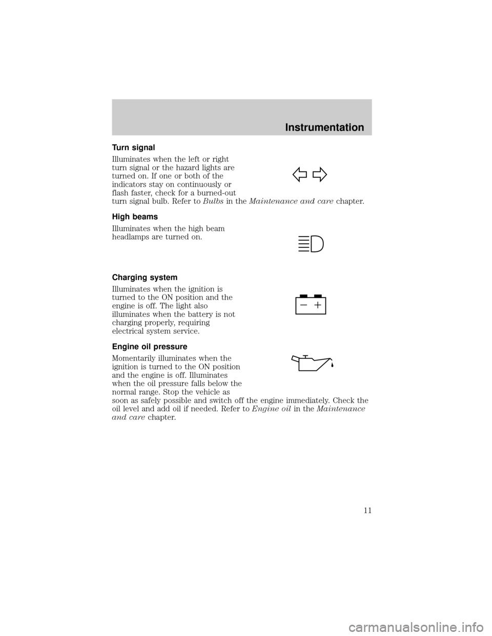
Turn signal
Illuminates when the left or right
turn signal or the hazard lights are
turned on. If one or both of the
indicators stay on continuously or
flash faster, check for a burned-out
turn signal bulb. Refer toBulbsin theMaintenance and carechapter.
High beams
Illuminates when the high beam
headlamps are turned on.
Charging system
Illuminates when the ignition is
turned to the ON position and the
engine is off. The light also
illuminates when the battery is not
charging properly, requiring
electrical system service.
Engine oil pressure
Momentarily illuminates when the
ignition is turned to the ON position
and the engine is off. Illuminates
when the oil pressure falls below the
normal range. Stop the vehicle as
soon as safely possible and switch off the engine immediately. Check the
oil level and add oil if needed. Refer toEngine oilin theMaintenance
and carechapter.
Instrumentation
11
Page 17 of 240
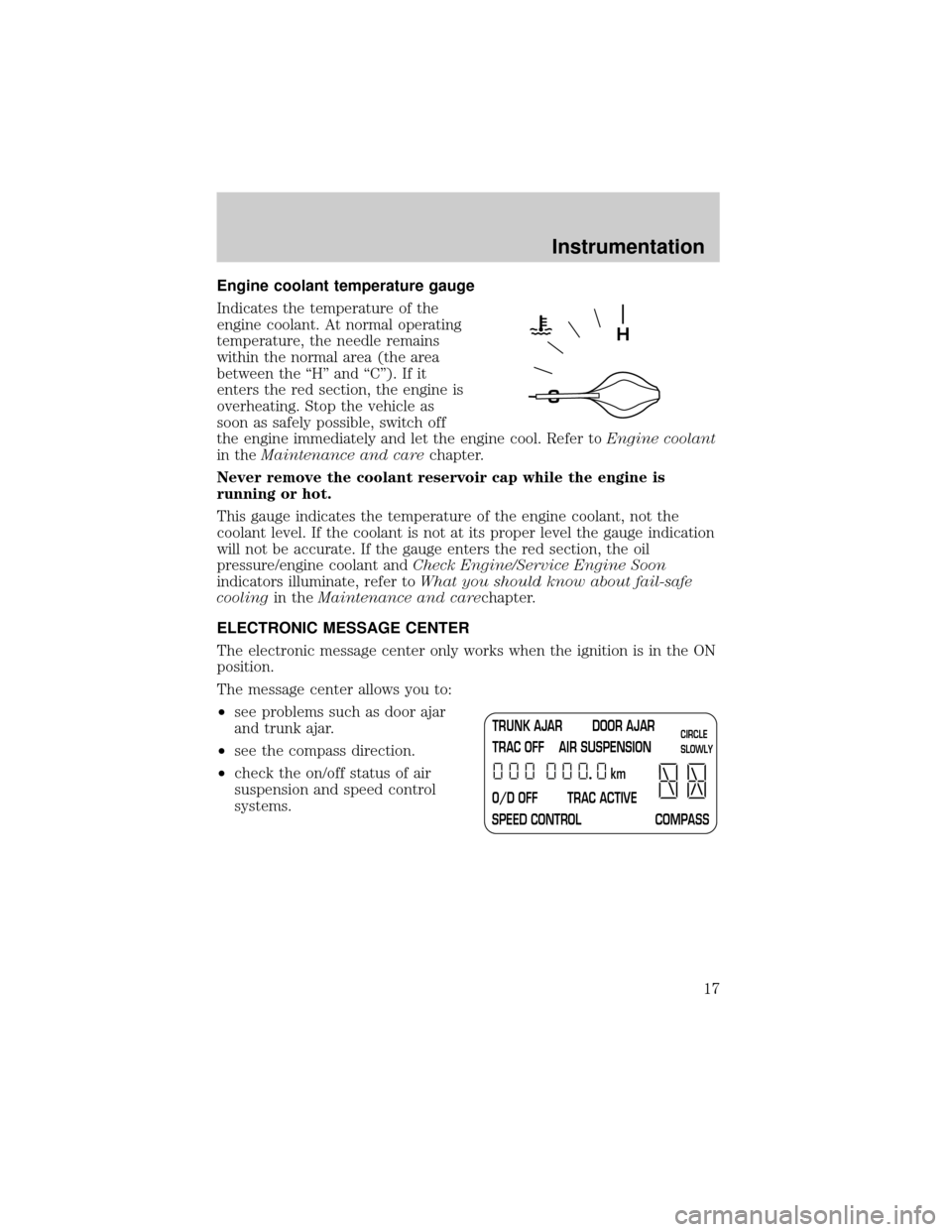
Engine coolant temperature gauge
Indicates the temperature of the
engine coolant. At normal operating
temperature, the needle remains
within the normal area (the area
between the ªHº and ªCº). If it
enters the red section, the engine is
overheating. Stop the vehicle as
soon as safely possible, switch off
the engine immediately and let the engine cool. Refer toEngine coolant
in theMaintenance and carechapter.
Never remove the coolant reservoir cap while the engine is
running or hot.
This gauge indicates the temperature of the engine coolant, not the
coolant level. If the coolant is not at its proper level the gauge indication
will not be accurate. If the gauge enters the red section, the oil
pressure/engine coolant andCheck Engine/Service Engine Soon
indicators illuminate, refer toWhat you should know about fail-safe
coolingin theMaintenance and carechapter.
ELECTRONIC MESSAGE CENTER
The electronic message center only works when the ignition is in the ON
position.
The message center allows you to:
²see problems such as door ajar
and trunk ajar.
²see the compass direction.
²check the on/off status of air
suspension and speed control
systems.
H
TRUNK AJAR DOOR AJAR
TRAC OFF AIR SUSPENSION
O/D OFF TRAC ACTIVE
SPEED CONTROL COMPASSkmCIRCLE
SLOWLY
Instrumentation
17
Page 150 of 240
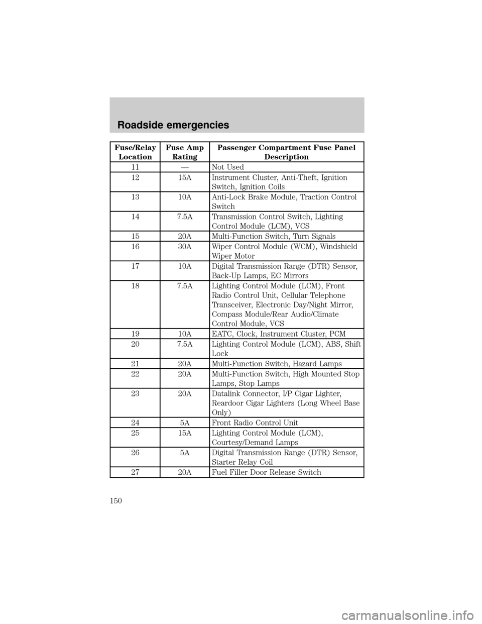
Fuse/Relay
LocationFuse Amp
RatingPassenger Compartment Fuse Panel
Description
11 Ð Not Used
12 15A Instrument Cluster, Anti-Theft, Ignition
Switch, Ignition Coils
13 10A Anti-Lock Brake Module, Traction Control
Switch
14 7.5A Transmission Control Switch, Lighting
Control Module (LCM), VCS
15 20A Multi-Function Switch, Turn Signals
16 30A Wiper Control Module (WCM), Windshield
Wiper Motor
17 10A Digital Transmission Range (DTR) Sensor,
Back-Up Lamps, EC Mirrors
18 7.5A Lighting Control Module (LCM), Front
Radio Control Unit, Cellular Telephone
Transceiver, Electronic Day/Night Mirror,
Compass Module/Rear Audio/Climate
Control Module, VCS
19 10A EATC, Clock, Instrument Cluster, PCM
20 7.5A Lighting Control Module (LCM), ABS, Shift
Lock
21 20A Multi-Function Switch, Hazard Lamps
22 20A Multi-Function Switch, High Mounted Stop
Lamps, Stop Lamps
23 20A Datalink Connector, I/P Cigar Lighter,
Reardoor Cigar Lighters (Long Wheel Base
Only)
24 5A Front Radio Control Unit
25 15A Lighting Control Module (LCM),
Courtesy/Demand Lamps
26 5A Digital Transmission Range (DTR) Sensor,
Starter Relay Coil
27 20A Fuel Filler Door Release Switch
Roadside emergencies
150
Page 166 of 240
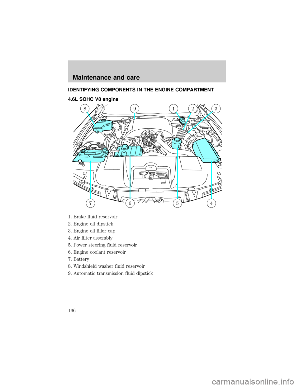
IDENTIFYING COMPONENTS IN THE ENGINE COMPARTMENT
4.6L SOHC V8 engine
1. Brake fluid reservoir
2. Engine oil dipstick
3. Engine oil filler cap
4. Air filter assembly
5. Power steering fluid reservoir
6. Engine coolant reservoir
7. Battery
8. Windshield washer fluid reservoir
9. Automatic transmission fluid dipstick
89123
6547
Maintenance and care
166
Page 167 of 240
ENGINE OIL
Checking the engine oil
Refer to the scheduled maintenance guide for the appropriate intervals
for checking the engine oil.
1. Make sure the vehicle is on level ground.
2. Turn the engine off and wait up to 10 minutes for the oil to drain into
the oil pan.
3. Set the parking brake and ensure the gearshift is securely latched in P
(Park).
4. Open the hood. Protect yourself from engine heat.
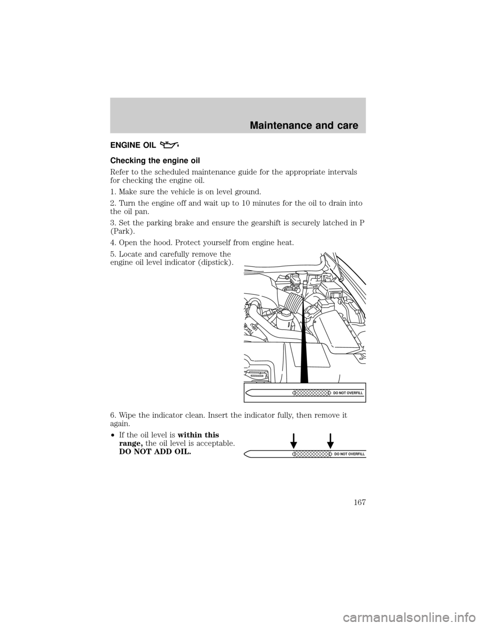
5. Locate and carefully remove the
engine oil level indicator (dipstick).
6. Wipe the indicator clean. Insert the indicator fully, then remove it
again.
²If the oil level iswithin this
range,the oil level is acceptable.
DO NOT ADD OIL.
DO NOT OVERFILL
DO NOT OVERFILL
Maintenance and care
167
Page 168 of 240
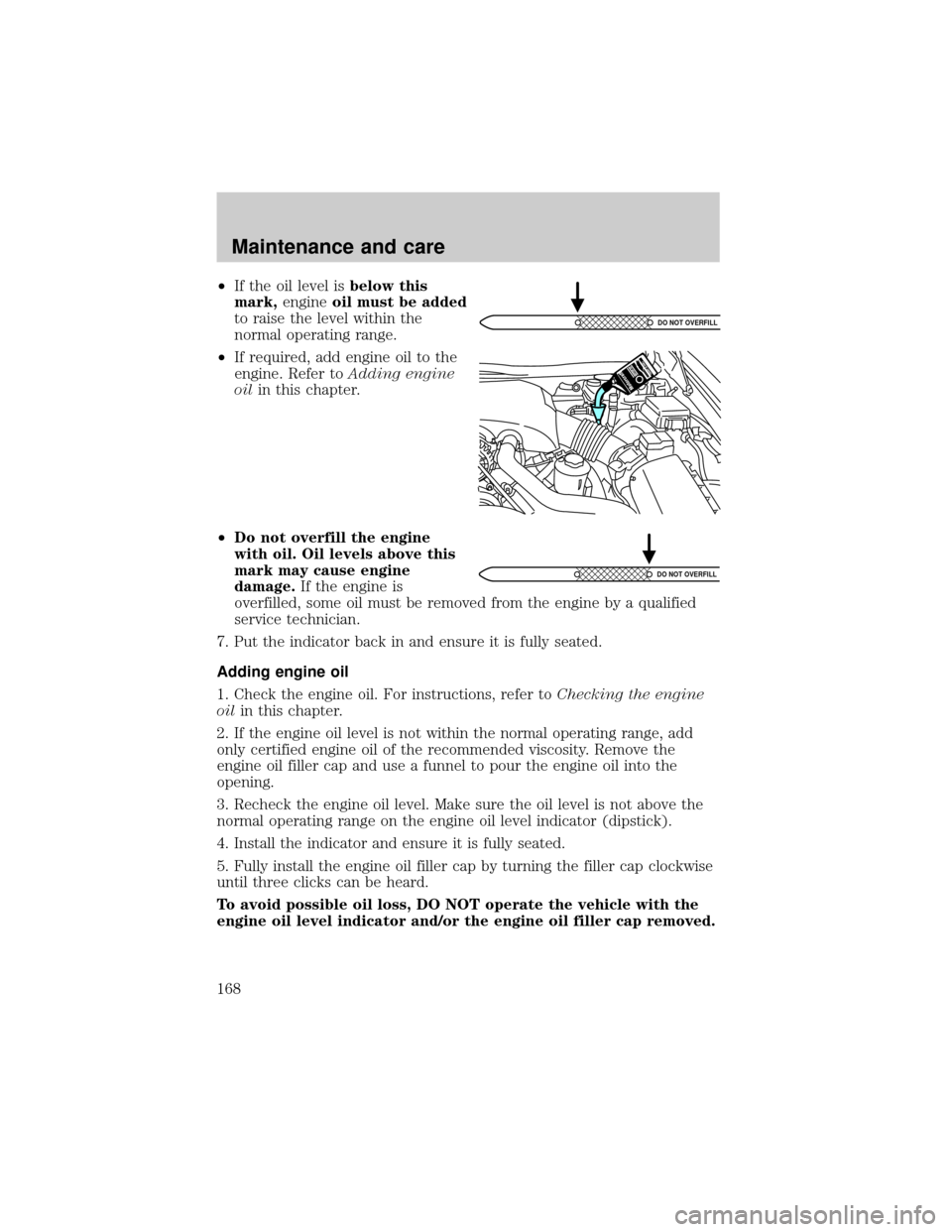
²If the oil level isbelow this
mark,engineoil must be added
to raise the level within the
normal operating range.
²If required, add engine oil to the
engine. Refer toAdding engine
oilin this chapter.
²Do not overfill the engine
with oil. Oil levels above this
mark may cause engine
damage.If the engine is
overfilled, some oil must be removed from the engine by a qualified
service technician.
7. Put the indicator back in and ensure it is fully seated.
Adding engine oil
1. Check the engine oil. For instructions, refer toChecking the engine
oilin this chapter.
2. If the engine oil level is not within the normal operating range, add
only certified engine oil of the recommended viscosity. Remove the
engine oil filler cap and use a funnel to pour the engine oil into the
opening.
3. Recheck the engine oil level. Make sure the oil level is not above the
normal operating range on the engine oil level indicator (dipstick).
4. Install the indicator and ensure it is fully seated.
5. Fully install the engine oil filler cap by turning the filler cap clockwise
until three clicks can be heard.
To avoid possible oil loss, DO NOT operate the vehicle with the
engine oil level indicator and/or the engine oil filler cap removed.
DO NOT OVERFILL
DO NOT OVERFILL
Maintenance and care
168
Page 169 of 240
Engine oil and filter recommendations
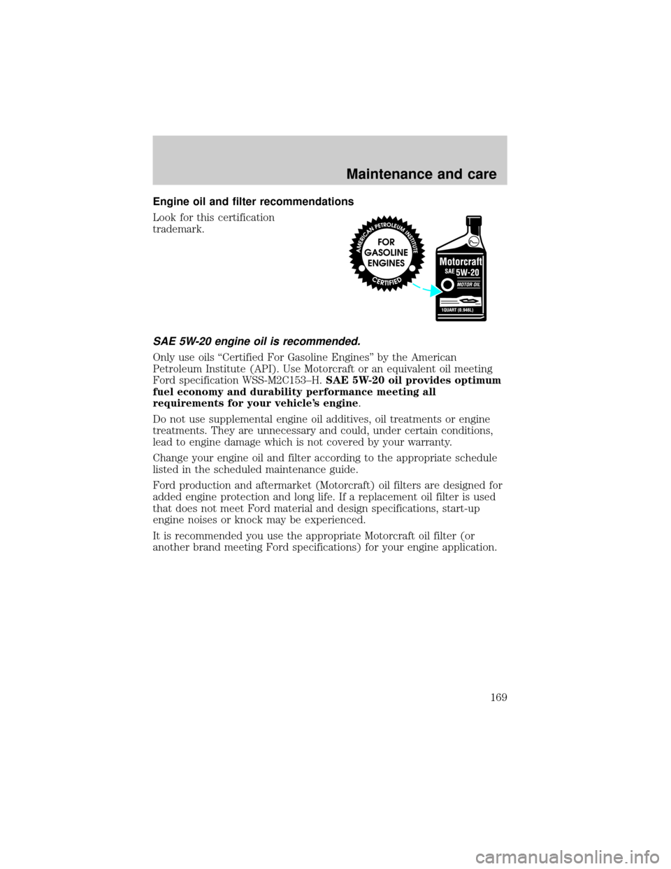
Look for this certification
trademark.
SAE 5W-20 engine oil is recommended.
Only use oils ªCertified For Gasoline Enginesº by the American
Petroleum Institute (API). Use Motorcraft or an equivalent oil meeting
Ford specification WSS-M2C153±H.SAE 5W-20 oil provides optimum
fuel economy and durability performance meeting all
requirements for your vehicle's engine.
Do not use supplemental engine oil additives, oil treatments or engine
treatments. They are unnecessary and could, under certain conditions,
lead to engine damage which is not covered by your warranty.
Change your engine oil and filter according to the appropriate schedule
listed in the scheduled maintenance guide.
Ford production and aftermarket (Motorcraft) oil filters are designed for
added engine protection and long life. If a replacement oil filter is used
that does not meet Ford material and design specifications, start-up
engine noises or knock may be experienced.
It is recommended you use the appropriate Motorcraft oil filter (or
another brand meeting Ford specifications) for your engine application.
Maintenance and care
169
Page 172 of 240
²Freeze protection down to -36É C (-34É F).
²Boiling protection up to 129É C (265É F).
²Protection against rust and other forms of corrosion.
²Enables calibrated gauges to work properly.
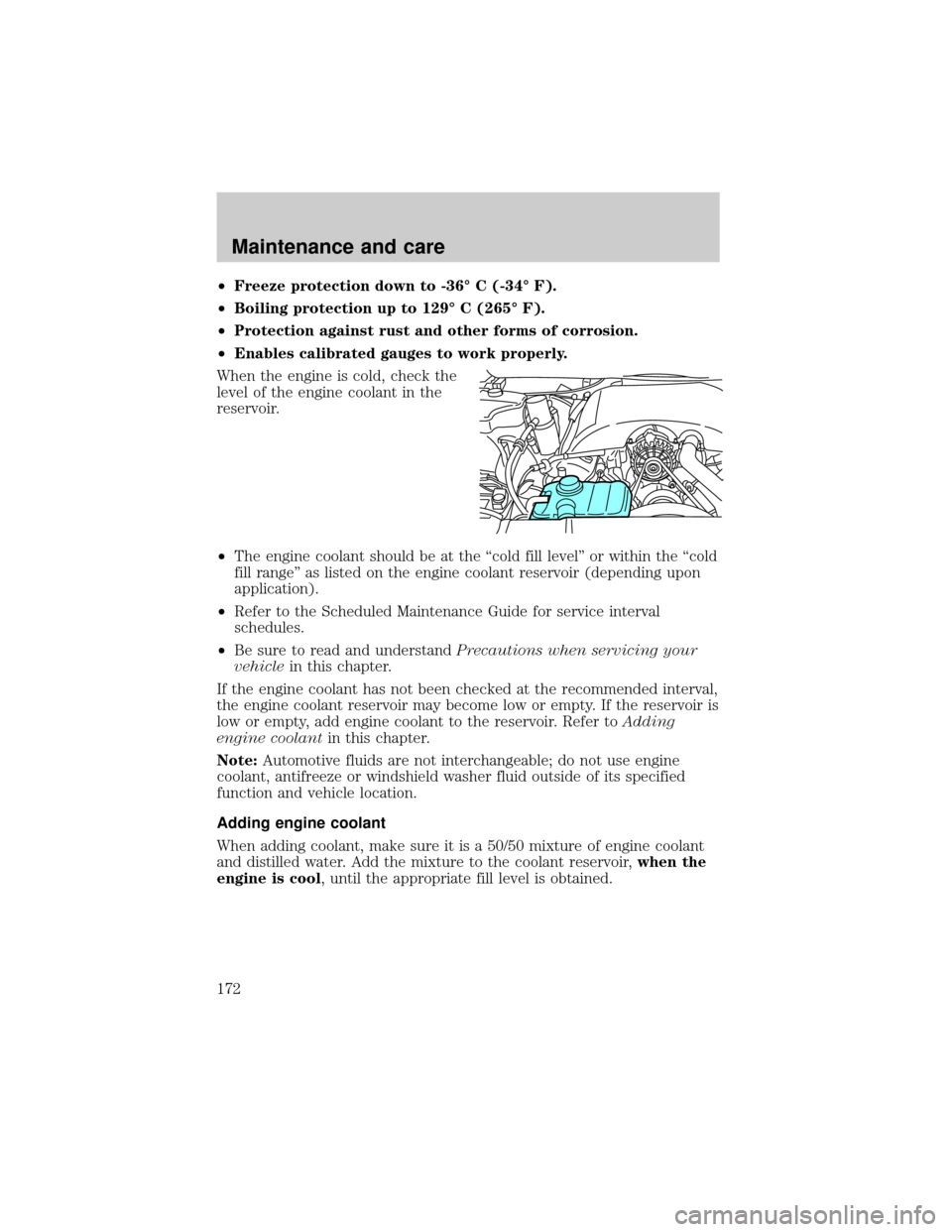
When the engine is cold, check the
level of the engine coolant in the
reservoir.
²The engine coolant should be at the ªcold fill levelº or within the ªcold
fill rangeº as listed on the engine coolant reservoir (depending upon
application).
²Refer to the Scheduled Maintenance Guide for service interval
schedules.
²Be sure to read and understandPrecautions when servicing your
vehiclein this chapter.
If the engine coolant has not been checked at the recommended interval,
the engine coolant reservoir may become low or empty. If the reservoir is
low or empty, add engine coolant to the reservoir. Refer toAdding
engine coolantin this chapter.
Note:Automotive fluids are not interchangeable; do not use engine
coolant, antifreeze or windshield washer fluid outside of its specified
function and vehicle location.
Adding engine coolant
When adding coolant, make sure it is a 50/50 mixture of engine coolant
and distilled water. Add the mixture to the coolant reservoir,when the
engine is cool, until the appropriate fill level is obtained.
Maintenance and care
172
Page 201 of 240
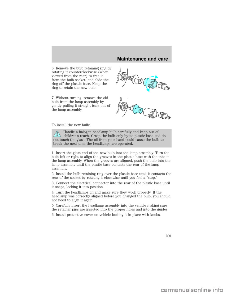
6. Remove the bulb retaining ring by
rotating it counterclockwise (when
viewed from the rear) to free it
from the bulb socket, and slide the
ring off the plastic base. Keep the
ring to retain the new bulb.
7. Without turning, remove the old
bulb from the lamp assembly by
gently pulling it straight back out of
the lamp assembly.
To install the new bulb:
Handle a halogen headlamp bulb carefully and keep out of
children's reach. Grasp the bulb only by its plastic base and do
not touch the glass. The oil from your hand could cause the bulb to
break the next time the headlamps are operated.
1. Insert the glass end of the new bulb into the lamp assembly. Turn the
bulb left or right to align the grooves in the plastic base with the tabs in
the lamp assembly. When the grooves are aligned, push the bulb into the
lamp assembly until the plastic base contacts the rear of the lamp
assembly.
2. Install the bulb retaining ring over the plastic base until it contacts the
rear of the socket by rotating it clockwise until you feel a ªstop.º
3. Connect the electrical connector into the rear of the plastic base until
it snaps, locking it into position.
4. Turn the headlamps on and make sure they work properly. If the
headlamp was correctly aligned before you changed the bulb, you should
not need to align it again.
5. Carefully insert the headlamp assembly into the vehicle making sure
the retainer pins are inserted into the proper holes and into the guides.
6. Install protective cover on vehicle locking it in place with knobs.
Maintenance and care
201