turn signal LINCOLN TOWN CAR 2001 Owners Manual
[x] Cancel search | Manufacturer: LINCOLN, Model Year: 2001, Model line: TOWN CAR, Model: LINCOLN TOWN CAR 2001Pages: 240, PDF Size: 1.92 MB
Page 6 of 240
OFF
P
PANEL
DIMLO
F
S
OFF
MIST
RESUME
SET ACCEL
COAST
OFF
ONNEXT
MODEVOL
TEMP FAN
102030405060
70
80
90
100
120206080
40100
120
160 140
180MPHkm/h110HF
E1
2FILL ON
LEFT<
CHECK
CAP
SERVICE
ENGINE
SOON
kmCIRCLE
SLOWLY FUEL ECON
DIST TO EMPTY
AVG SPEED
TRIP A B
E/M
km MILES/GALWASHER
LTR/100km
BRAKE
O/D OFF TRAC ACTIVE
SPEED CONTROL COMPASS
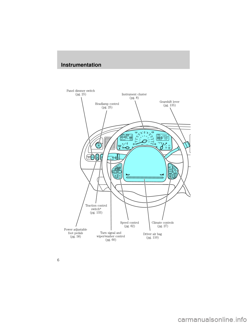
Panel dimmer switch
(pg. 25)
Headlamp control
(pg. 25)Instrument cluster
(pg. 8)
Gearshift lever
(pg. 135)
Climate controls
(pg. 27)
Driver air bag
(pg. 110) Speed control
(pg. 62)
Turn signal and
wiper/washer control
(pg. 60) Traction control
switch*
(pg. 133)
Power adjustable
foot pedals
(pg. 58)
Instrumentation
6
Page 11 of 240
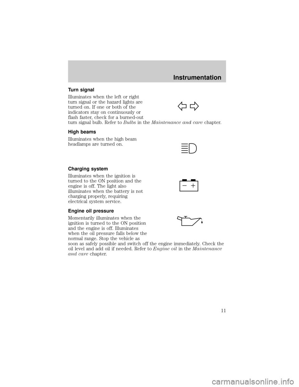
Turn signal
Illuminates when the left or right
turn signal or the hazard lights are
turned on. If one or both of the
indicators stay on continuously or
flash faster, check for a burned-out
turn signal bulb. Refer toBulbsin theMaintenance and carechapter.
High beams
Illuminates when the high beam
headlamps are turned on.
Charging system
Illuminates when the ignition is
turned to the ON position and the
engine is off. The light also
illuminates when the battery is not
charging properly, requiring
electrical system service.
Engine oil pressure
Momentarily illuminates when the
ignition is turned to the ON position
and the engine is off. Illuminates
when the oil pressure falls below the
normal range. Stop the vehicle as
soon as safely possible and switch off the engine immediately. Check the
oil level and add oil if needed. Refer toEngine oilin theMaintenance
and carechapter.
Instrumentation
11
Page 15 of 240
Supplemental restraint system (SRS) warning chime
For information on the SRS warning chime, refer to theSeating and
safety restraintschapter.
Key-in-ignition warning chime
Sounds when the key is left in the ignition in the OFF/LOCK or ACC
position and the driver's door is opened.
Headlamps on warning chime
Sounds when the headlamps or parking lamps are on, the ignition is off
(and the key is not in the ignition) and the driver's door is opened.
Turn signal chime (if equipped)
Sounds when the turn signal lever has been activated to signal a turn
and not turned off after the vehicle is driven more than 0.8 km
(1/2 mile).
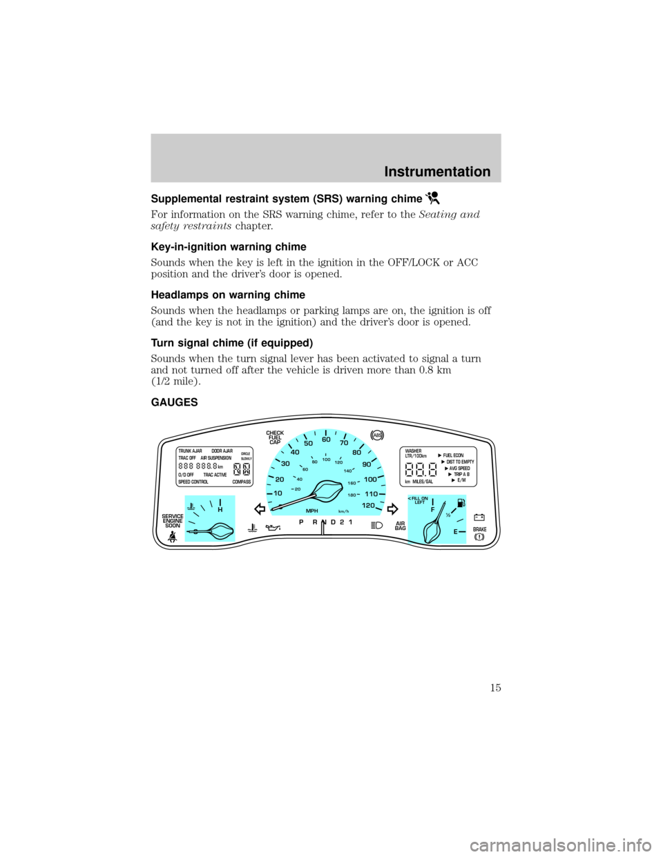
GAUGES
10
2030405060
70
80
90
100
120206080
40100
120
160 140
180
P R N D 2 1
MPHkm/h
110
HF
E1
2
FILL ON
LEFT<
AIR
BAG CHECK
FUEL
CAP
SERVICE
ENGINE
SOON
TRUNK AJAR DOOR AJAR
TRAC OFF AIR SUSPENSION
O/D OFF TRAC ACTIVE
SPEED CONTROL COMPASSkmCIRCLE
SLOWLY FUEL ECON
DIST TO EMPTY
AVG SPEED
TRIP A B
E/M
km MILES/GALWASHER
LTR/100km
BRAKE
Instrumentation
15
Page 52 of 240
Phone mode
This feature allows you to control
the factory-installed cellular phone
(if equipped) through the radio
controls.
²Press the phone/mute control to enter phone mode. The playing media
will mute.
²Use SEEK, TUNE or radio presets 1 through 6 to select a phone
number previously programmed in the phone.
²Press the phone/mute control again to send and end calls.
This control will mute the playing media even if your vehicle is not
equipped with a factory-installed cellular phone.
Press the control again to return to the playing media.
Digital signal processing (if equipped)
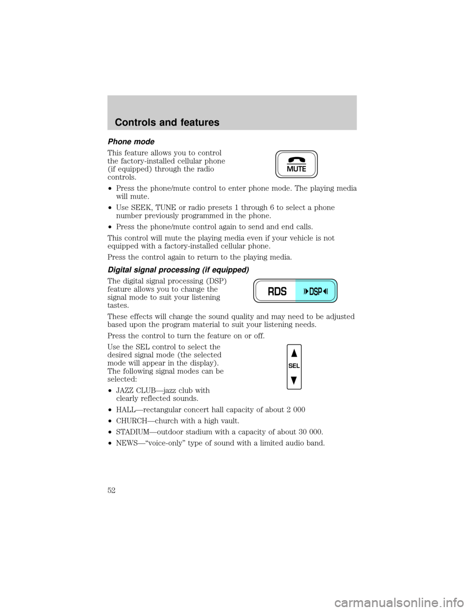
The digital signal processing (DSP)
feature allows you to change the
signal mode to suit your listening
tastes.
These effects will change the sound quality and may need to be adjusted
based upon the program material to suit your listening needs.
Press the control to turn the feature on or off.
Use the SEL control to select the
desired signal mode (the selected
mode will appear in the display).
The following signal modes can be
selected:
²JAZZ CLUBÐjazz club with
clearly reflected sounds.
²HALLÐrectangular concert hall capacity of about 2 000
²CHURCHÐchurch with a high vault.
²STADIUMÐoutdoor stadium with a capacity of about 30 000.
²NEWSЪvoice-onlyº type of sound with a limited audio band.
MUTE
RDSDSP
SEL
Controls and features
52
Page 57 of 240

Radio frequency information
The Federal Communications Commission (FCC) and the Canadian Radio
and Telecommunications Commission(CRTC) establish the frequencies
AM and FM stations may use for their broadcasts. Allowable frequencies
are:
AM 530, 540±1600, 1610 kHz
FM 87.7, 87.9±107.7, 107.9 MHz
Not all frequencies are used in a given area.
Radio reception factors
Three factors can affect radio reception:
²Distance/strength.The further an FM signal travels, the weaker it is.
The listenable range of the average FM station is approximately 40 km
(24 miles). This range can be affected by ªsignal modulation.º Signal
modulation is a process radio stations use to increase their
strength/volume relative to other stations.
²Terrain.Hills, mountains and tall buildings between your vehicle's
antenna and the radio station signal can cause FM reception problems.
Static can be caused on AM stations by power lines, electric fences,
traffic lights and thunderstorms. Moving away from an interfering
structure (out of its ªshadowº) returns your reception to normal.
²Station overload.Weak signals are sometimes captured by stronger
signals when you pass a broadcast tower. A stronger signal may
temporarily overtake a weaker signal and play while the weak station
frequency is displayed.
The audio system automatically switches to single channel reception if it
will improve the reception of a station normally received in stereo.
Audio system warranties and service
Refer to theWarranty Guidefor audio system warranty information.
If service is necessary, see your dealer or a qualified technician.
Controls and features
57
Page 60 of 240
KEYS
The vehicle is equipped with a master key and valet key lock system.
The master key will access doors, trunk, glove box, ignition and remote
trunk release. The valet key (marked ªvaletº) will access doors and
ignition only. Before using this key, lock the trunk remote control to
disable theTrunk remote controlon the drivers door, then lock the
glove compartment with your master key.
TILT STEERING
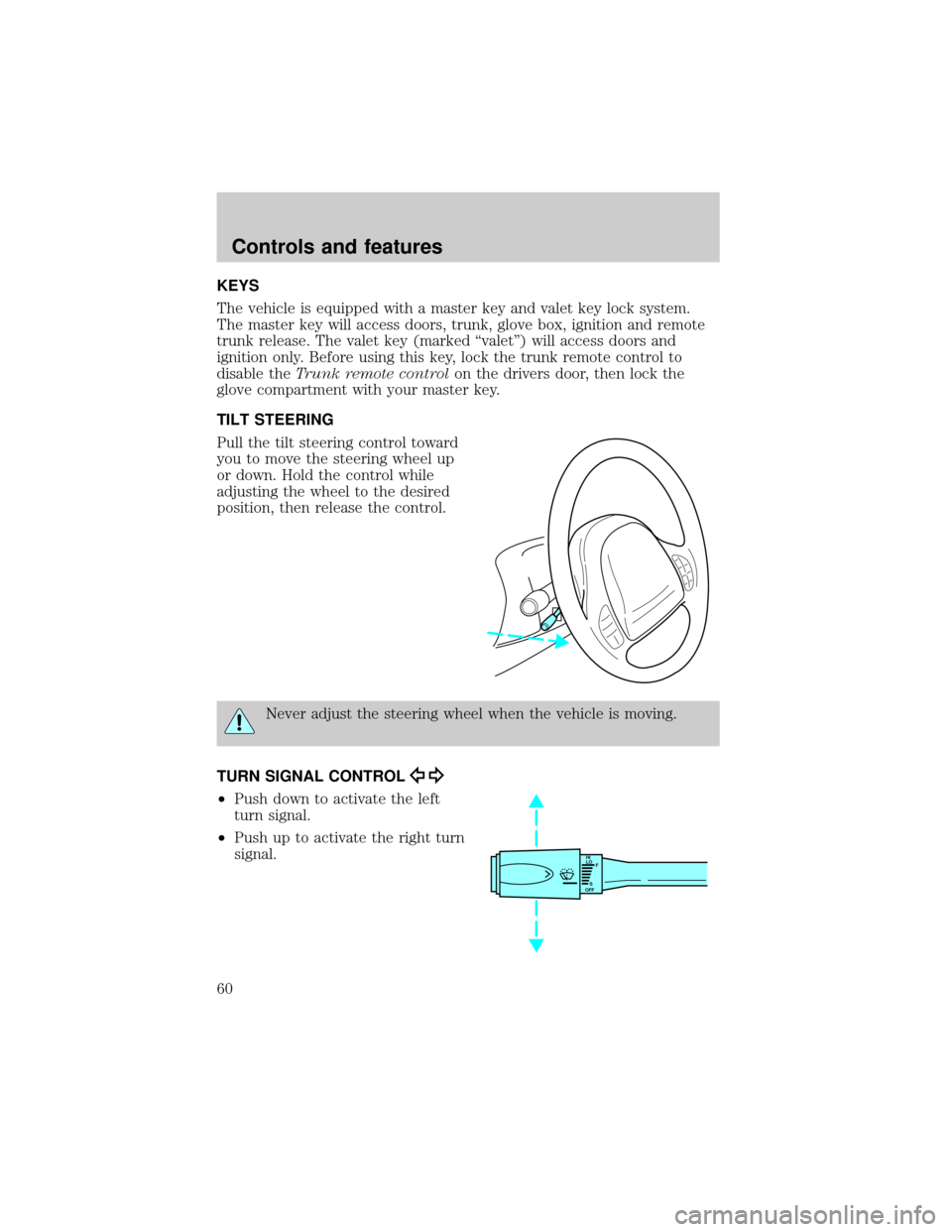
Pull the tilt steering control toward
you to move the steering wheel up
or down. Hold the control while
adjusting the wheel to the desired
position, then release the control.
Never adjust the steering wheel when the vehicle is moving.
TURN SIGNAL CONTROL
²Push down to activate the left
turn signal.
²Push up to activate the right turn
signal.
HI
LO
F
S
OFF
Controls and features
60
Page 69 of 240
Operating the HomeLinkTUniversal Transceiver
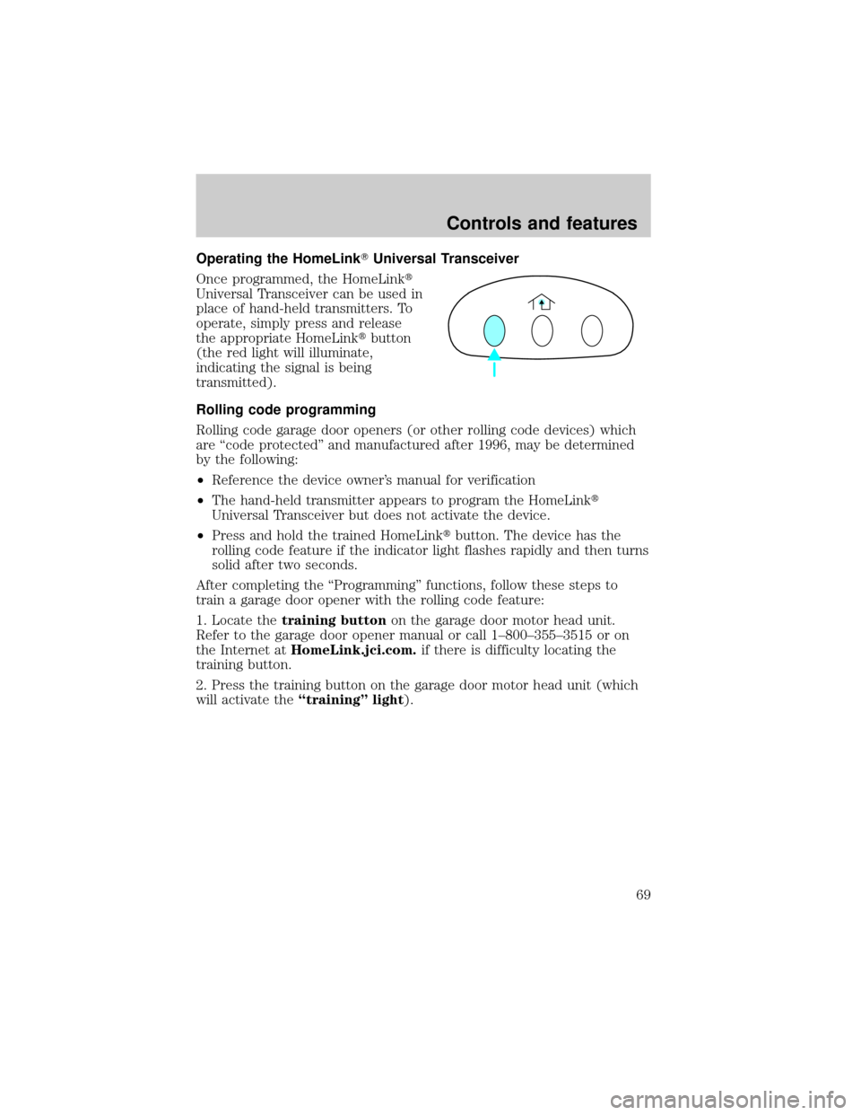
Once programmed, the HomeLinkt
Universal Transceiver can be used in
place of hand-held transmitters. To
operate, simply press and release
the appropriate HomeLinktbutton
(the red light will illuminate,
indicating the signal is being
transmitted).
Rolling code programming
Rolling code garage door openers (or other rolling code devices) which
are ªcode protectedº and manufactured after 1996, may be determined
by the following:
²Reference the device owner's manual for verification
²The hand-held transmitter appears to program the HomeLinkt
Universal Transceiver but does not activate the device.
²Press and hold the trained HomeLinktbutton. The device has the
rolling code feature if the indicator light flashes rapidly and then turns
solid after two seconds.
After completing the ªProgrammingº functions, follow these steps to
train a garage door opener with the rolling code feature:
1. Locate thetraining buttonon the garage door motor head unit.
Refer to the garage door opener manual or call 1±800±355±3515 or on
the Internet atHomeLink.jci.com.if there is difficulty locating the
training button.
2. Press the training button on the garage door motor head unit (which
will activate theªtrainingº light).
Controls and features
69
Page 150 of 240
Fuse/Relay
LocationFuse Amp
RatingPassenger Compartment Fuse Panel
Description
11 Ð Not Used
12 15A Instrument Cluster, Anti-Theft, Ignition
Switch, Ignition Coils
13 10A Anti-Lock Brake Module, Traction Control
Switch
14 7.5A Transmission Control Switch, Lighting
Control Module (LCM), VCS
15 20A Multi-Function Switch, Turn Signals
16 30A Wiper Control Module (WCM), Windshield
Wiper Motor
17 10A Digital Transmission Range (DTR) Sensor,
Back-Up Lamps, EC Mirrors
18 7.5A Lighting Control Module (LCM), Front
Radio Control Unit, Cellular Telephone
Transceiver, Electronic Day/Night Mirror,
Compass Module/Rear Audio/Climate
Control Module, VCS
19 10A EATC, Clock, Instrument Cluster, PCM
20 7.5A Lighting Control Module (LCM), ABS, Shift
Lock
21 20A Multi-Function Switch, Hazard Lamps
22 20A Multi-Function Switch, High Mounted Stop
Lamps, Stop Lamps
23 20A Datalink Connector, I/P Cigar Lighter,
Reardoor Cigar Lighters (Long Wheel Base
Only)
24 5A Front Radio Control Unit
25 15A Lighting Control Module (LCM),
Courtesy/Demand Lamps
26 5A Digital Transmission Range (DTR) Sensor,
Starter Relay Coil
27 20A Fuel Filler Door Release Switch
Roadside emergencies
150
Page 199 of 240

Allow the vehicle to sit for at least eight hours without starting the
engine. Then, start the engine and complete the above driving cycle. The
engine must warm up to its normal operating temperature. Once started,
do not turn off the engine until the above driving cycle is complete.
BULBS
Replacing exterior bulbs
Check the operation of the following lamps frequently:
²Headlamps
²Tail lamps
²Brakelamps
²High-mount brakelamp
²Turn signals
²Backup lamps
²License plate lamp
Do not remove lamp bulbs unless they will be replaced immediately. If a
bulb is removed for an extended period of time, contaminants may enter
the lamp housings and affect performance.
Replacing headlamp bulbs
To remove the headlamp bulb:
1. Make sure headlamp switch is in OFF position.
2. Open the hood.
Maintenance and care
199
Page 202 of 240
Replacing front parking lamp/turn signal lamp bulbs
1. Make sure the headlamp control is in the OFF position.
2. Open the hood.
3. Twist the plastic knobs and remove the protective cover from the back
of the headlamps. Lift the cover and pull towards the windshield.
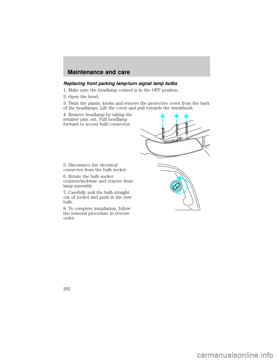
4. Remove headlamp by taking the
retainer pins out. Pull headlamp
forward to access bulb connector.
5. Disconnect the electrical
connector from the bulb socket.
6. Rotate the bulb socket
counterclockwise and remove from
lamp assembly.
7. Carefully pull the bulb straight
out of socket and push in the new
bulb.
8. To complete installation, follow
the removal procedure in reverse
order.
Maintenance and care
202