tow LOTUS ELISE 2005 Owners Manual
[x] Cancel search | Manufacturer: LOTUS, Model Year: 2005, Model line: ELISE, Model: LOTUS ELISE 2005Pages: 205, PDF Size: 4.51 MB
Page 7 of 205
Engine Compartment Fuses ...................................137
Footwell Sited Fuses ...............................................
138
Headlamp Alignment .....................................................
139
Bulb Replacement ........................................................
142
Headlamp Bulb ........................................................
142
Front Turn Indicator Lamp Bulb ...............................
143
Side Repeater Lamp Bulb .......................................
144
Rear Lamp Cluster Bulb ..........................................
144
High Mounted Stoplamp Bulb .................................
144
Licence Plate Lamp Bulb ........................................
144
Interior Lamp Bulb ...................................................
145
Side Marker Lamp Bulb ...........................................
145
16. LIFTING & TOWING
Towing Eye ...............................................................146
Towing a Trailer .............................................................147
Car Tie-Down ...............................................................
147
Lifting Your Car .............................................................148
Fuel Tank Undershi
eld ..................................................149
17. A
CCESSORIES
Accessories & Modifications .........................................150
Storing Your Elise .........................................................
152
18. RECOMMENDED LUBRICANTS
Engine ...............................................................
153
Transmission ...............................................................
154
Br
akes & Clutch ............................................................154
Engine Coolant Additive ................................................
154
19. TECHNICAL DATA .......................................................155
20. WARRANTY INDEX .....................................................161
21. ALPHABETICAL INDEX ..............................................188
Contents
5
oh_croft_InD.indd 520/05/2004 07:58:40ProCarManuals.com
Page 16 of 205
NOTICE: DO NOT push or tow start the car; or turn off the igni-
tion at engine speeds above idle; or run the fuel tank dry: Any of these actions may damage the catalytic converter.
Before driving the car:
• Check tires for damage, wear and proper inflation.
Under-infla-
tion causes increased rolling resistance and uses more fuel.
(Please refer to the section in this handbook on tires, page 115).
• Check all windows, mirrors and lights are clear and unob
-
structed and all lights are correctly working.
• Check that the engine cover and front body access panels
are correctly latched;
• Adjust the seat and mirrors, and familiarise yourself with
the controls.
• Check all instruments and warning lamps (‘tell tales’) are reading correctly.
• Ensure that both driver and passenger are properly restrained
by their seat belts.
Care of the Environment By virtue of its light weight, simple content, constructional
process and fuel efficiency, the Elise has a low environmental im
-
pact compared with many road cars. All drivers should, however,
be aware of the effect of motor car exhaust emissions on the
environment and drive in a way which minimises pollution by:
• Anticipating traffic flow to avoid needless acceleration
and braking.
• Using the highest suitable gear.
• Switching off rather than idling for long periods.
• Driving off as soon as it is safe to do so; it is not necessary or beneficial to the engine to allow extended idling from cold.
• Having the car serviced regularly as a poorly maintained car will use more fuel; have any engine faults attended to imme
-
diately.
• Considering the need to use the car for very short journeys.
The emissions produced by an engine are many times greater
when cold than when warm.
Safety Information
14
oh_croft_InD.indd 1420/05/2004 07:58:42ProCarManuals.com
Page 40 of 205
the doors will be ‘deadlocked’ meaning that the interior door release handles will not open the doors. In order to get
out of the car in an emergency when the doors are locked
see the section below ‘to unlock from inside’.
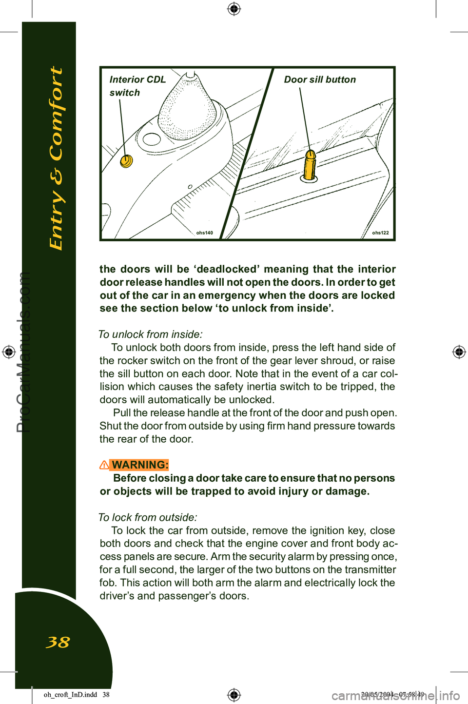
To unlock from inside: To unlock both doors from inside, press the left hand side of
the rocker switch on the front of the gear lever shroud, or raise
the sill button on each door. Note that in the event of a car col
-
lision which causes the safety inertia switch to be tripped, the doors will automatically be unlocked.
Pull the release handle at the front of the door and push open.
Shut the door from outside by using firm hand pressure towards the rear of the door.
WARNING: Before closing a door take care to ensure that no persons
or objects will be trapped to avoid injury or damage.
To lock from outside: To lock the car from outside, remove the ignition key, close
both doors and check that the engine cover and front body ac
-
cess panels are secure. Arm the security alarm by pressing once,
for a full second, the larger of the two buttons on the transmitter
fob. This action will both arm the alarm and electrically lock the driver’s and passenger’s doors.
ohs122
ohs140
Entry & Comfort
38
Interior CDL
switchDoor sill button
oh_croft_InD.indd 3820/05/2004 07:58:49ProCarManuals.com
Page 42 of 205
ohs149
NightDay
‘Lights On’ Buzzer
A ‘lights on’ reminder buzzer will sound if the lights are on, the
ignition is switched off, and the driver’s door is then opened.
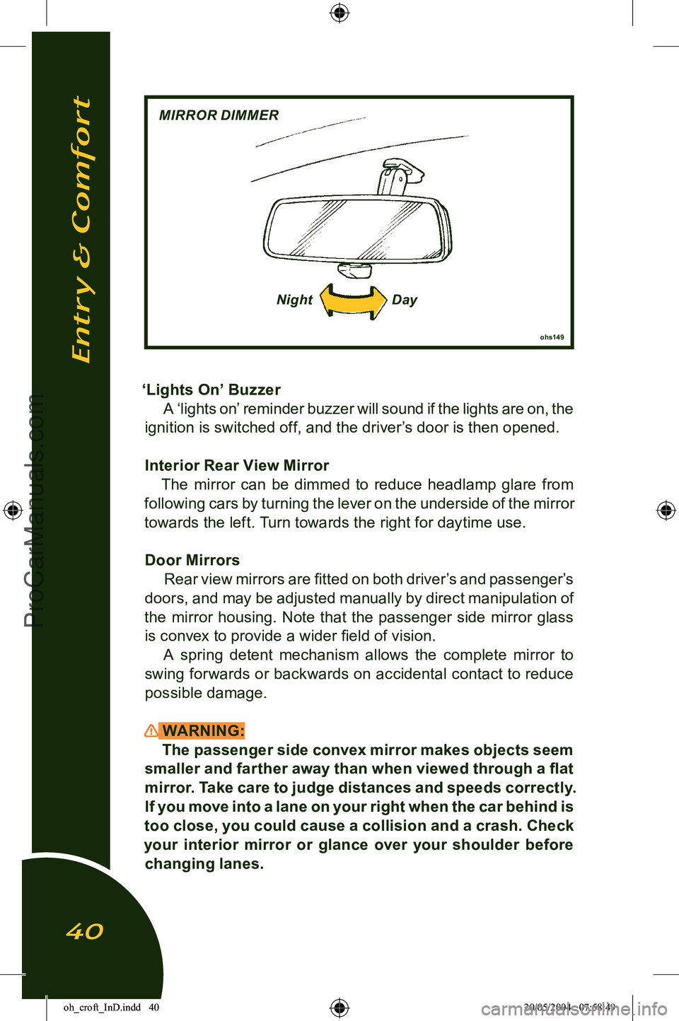
Interior Rear View Mirror The mirror can be dimmed to reduce headlamp glare from
following cars by turning the lever on the underside of the mirror
towards the left. Turn towards the right for daytime use.
Door Mirrors Rear view mirrors are fitted on both driver’s and passenger’s
doors, and may be adjusted manually by direct manipulation of
the mirror housing. Note that the passenger side mirror glass is convex to provide a wider field of vision. A spring detent mechanism allows the complete mirror to
swing forwards or backwards on accidental contact to reduce
possible damage.
WARNING: The passenger side convex mirror makes objects seem
smaller and farther away than when viewed through a flat
mirror. Take care to judge distances and speeds correctly.
If you move into a lane on your right when the car behind is
too close, you could cause a collision and a crash. Check
your interior mirror or glance over your shoulder before
changing lanes.
Entry & Comfort
40
MIRROR DIMMER
oh_croft_InD.indd 4020/05/2004 07:58:49ProCarManuals.com
Page 47 of 205
WARNING:
• Do not push or tow the car unless the key is first used to unlock the column and is then left in the lock. With
-
drawing the key will cause the steering to lock.
• Never remove the key from the ignition switch or turn off the ignition while the car is moving. Withdrawing the key
will cause the steering to lock and may cause an accident
resulting in serious injury or death.
• To reduce the risk of theft, or danger to a child remaining in the car, always remove the key when leaving a parked
car.
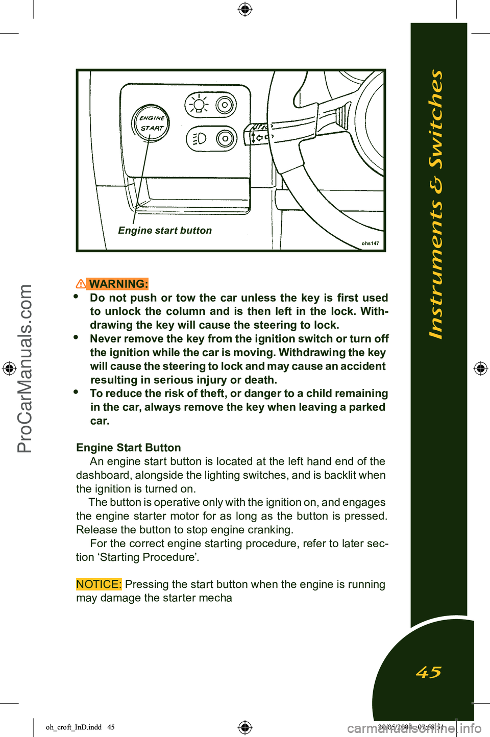
Engine Start Button An engine start button is located at the left hand end of the
dashboard, alongside the lighting switches, and is backlit when
the ignition is turned on. The button is operative only with the ignition on, and engages
the engine starter motor for as long as the button is pressed. Release the button to stop engine cranking.
For the correct engine starting procedure, refer to later sec
-
tion ‘Starting Procedure’.
NOTICE: Pressing the start button when the engine is running may damage the starter mecha
ohs147Engine start button
Instruments & Switches
45
oh_croft_InD.indd 4520/05/2004 07:58:51ProCarManuals.com
Page 60 of 205
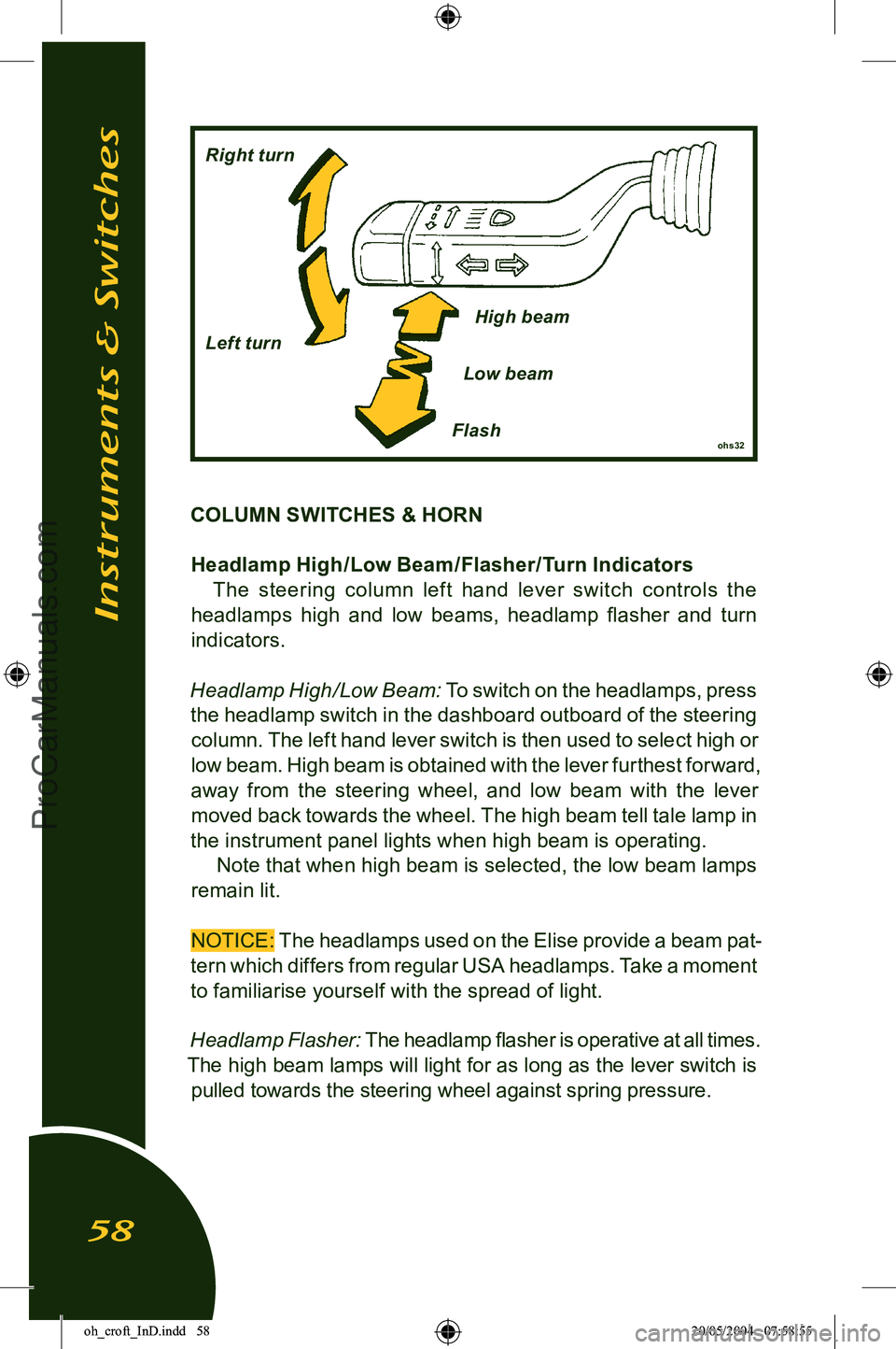
COLUMN SWITCHES & HORNHeadlamp High /Low Beam /Flasher/Turn Indicators The steering column lef t hand lever switch controls the
headlamps high and low beams, headlamp flasher and turn
indicators.
Headlamp High/Low Beam:
To switch on the headlamps, press
the headlamp switch in the dashboard outboard of the steering column. The left hand lever switch is then used to select high or
low beam. High beam is obtained with the lever furthest forward,
away from the steering wheel, and low beam with the lever moved back towards the wheel. The high beam tell tale lamp in
the instrument panel lights when high beam is operating.
Note that when high beam is selected, the low beam lamps
remain lit.
NOTICE:
The headlamps used on the Elise provide a beam pat-
tern which differs from regular USA headlamps. Take a moment
to familiarise yourself with the spread of light.
Headlamp Flasher:
The headlamp flasher is operative at all times.
The high beam lamps will light for as long as the lever switch is pulled towards the steering wheel against spring pressure.
Instruments & Switches
58
ohs32Flash
Right turn
Left turn
High beam
Low beam
oh_croft_InD.indd 5820/05/2004 07:58:55ProCarManuals.com
Page 66 of 205
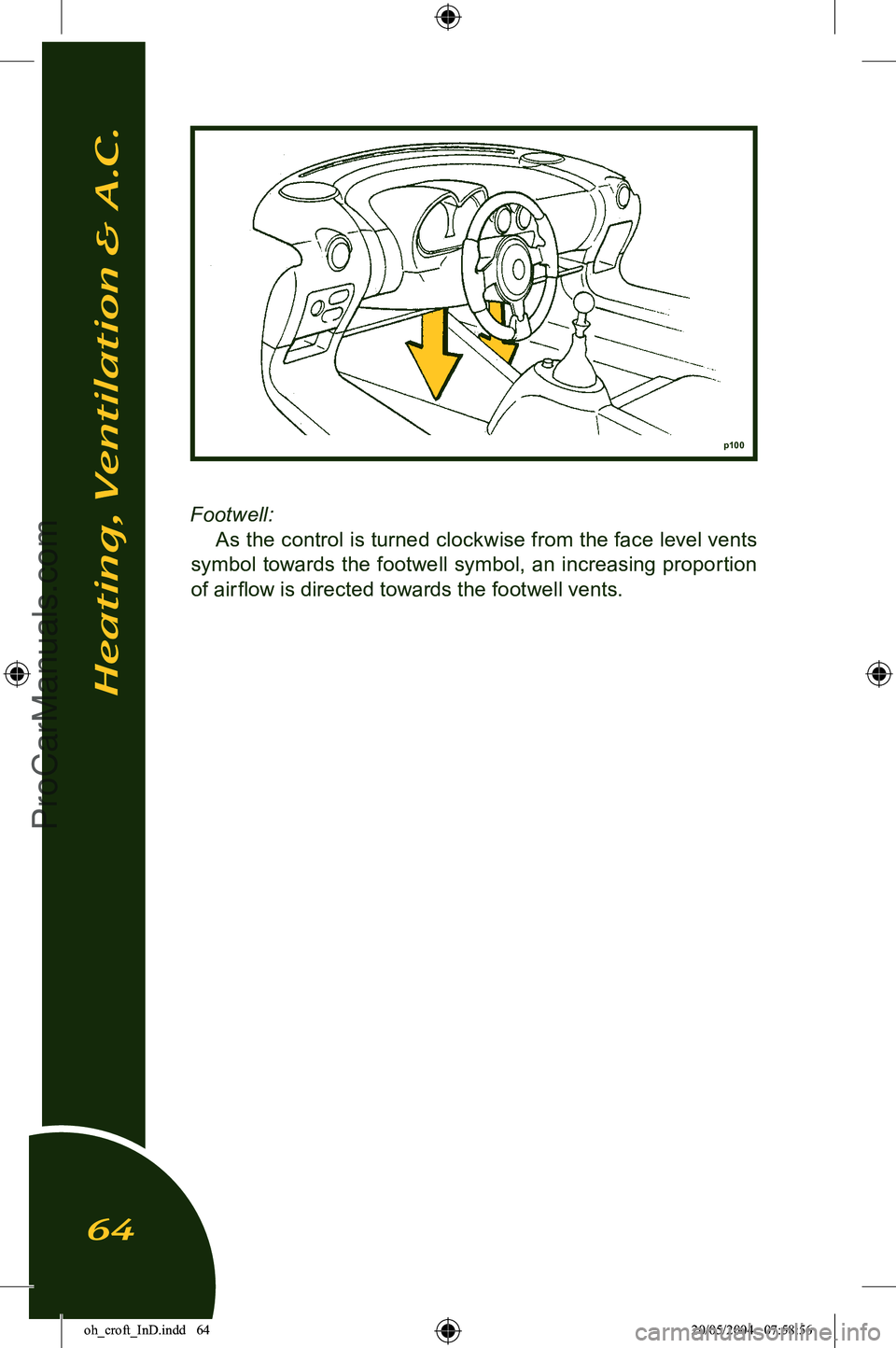
Footwell:
As the control is turned clockwise from the face level vents
symbol towards the footwell symbol, an increasing proportion
of air flow is directed towards the footwell vents.
p100
Heating, Ventilation & A.C.
64
oh_croft_InD.indd 6420/05/2004 07:58:56ProCarManuals.com
Page 72 of 205
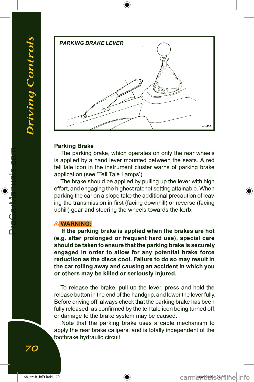
Parking BrakeThe parking brake, which operates on only the rear wheels
is applied by a hand lever mounted between the seats. A red
tell tale icon in the instrument cluster warns of parking brake application (see ‘Tell Tale Lamps’). The brake should be applied by pulling up the lever with high
effort, and engaging the highest ratchet setting attainable. When
parking the car on a slope take the additional precaution of leav
-
ing the transmission in first (facing downhill) or reverse (facing uphill) gear and steering the wheels towards the kerb.
WARNING: If the parking brake is applied when the brakes are hot
(e.g. after prolonged or frequent hard use), special care
should be taken to ensure that the parking brake is securely engaged in order to allow for any potential brake force
reduction as the discs cool. Failure to do so may result in
the car rolling away and causing an accident in which you
or others may be killed or seriously injured.
To release the brake, pull up the lever, press and hold the
release button in the end of the handgrip, and lower the lever fully.
Before driving off, always check that the parking brake has been
fully released, as confirmed by the tell tale icon being turned off,
or damage to the brake system may be caused. Note that the parking brake uses a cable mechanism to
apply the rear brake calipers, and is totally independent of the
footbrake hydraulic circuit.
Driving Controls
70
ohs138
PARKING BRAKE LEVER
oh_croft_InD.indd 7020/05/2004 07:58:58ProCarManuals.com
Page 73 of 205
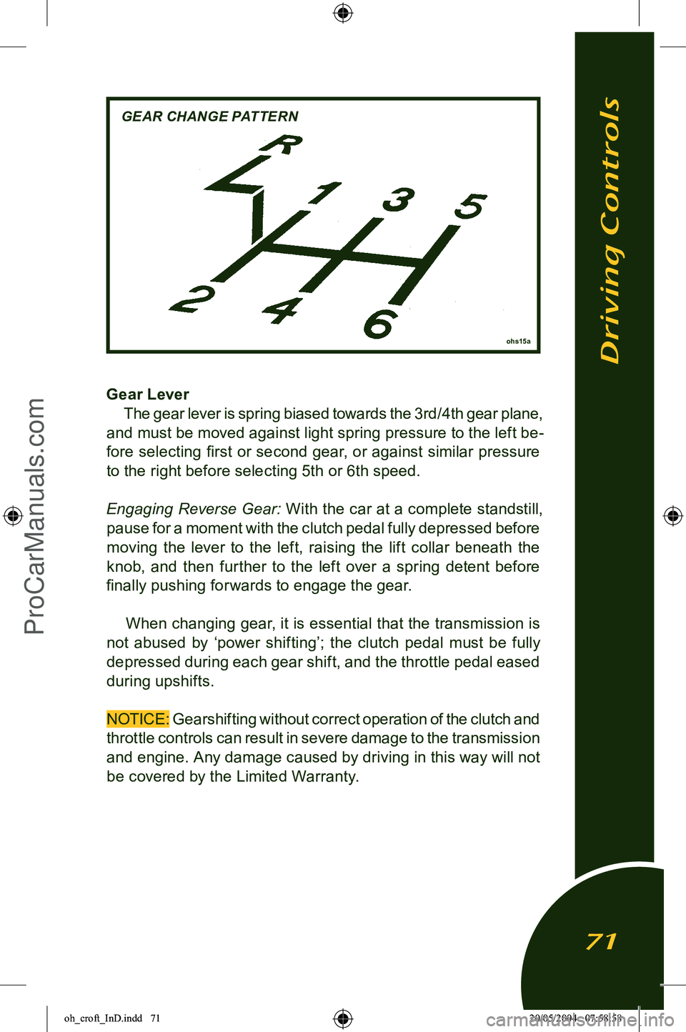
Gear LeverThe gear lever is spring biased towards the 3rd/4th gear plane,
and must be moved against light spring pressure to the left be
-
fore selecting first or second gear, or against similar pressure to the right before selecting 5th or 6th speed.
Engaging Reverse Gear: With the car at a complete standstill
,
pause for a moment with the clutch pedal fully depressed before
moving the lever to the left, raising the lift collar beneath the
knob, and then further to the left over a spring detent before
finally pushing forwards to engage the gear.
When changing gear, it is essential that the transmission is
not abused by ‘power shifting’; the clutch pedal must be fully
depressed during each gear shift, and the throttle pedal eased
during upshifts.
NOTICE: Gearshifting without correct operation of the clutch and
throttle controls can result in severe damage to the transmission
and engine. Any damage caused by driving in this way will not be covered by the Limited Warranty.
Driving Controls
71
ohs15a
GEAR CHANGE PATTERN
oh_croft_InD.indd 7120/05/2004 07:58:58ProCarManuals.com
Page 80 of 205
ohs93
REMOVING ACCESS PANEL
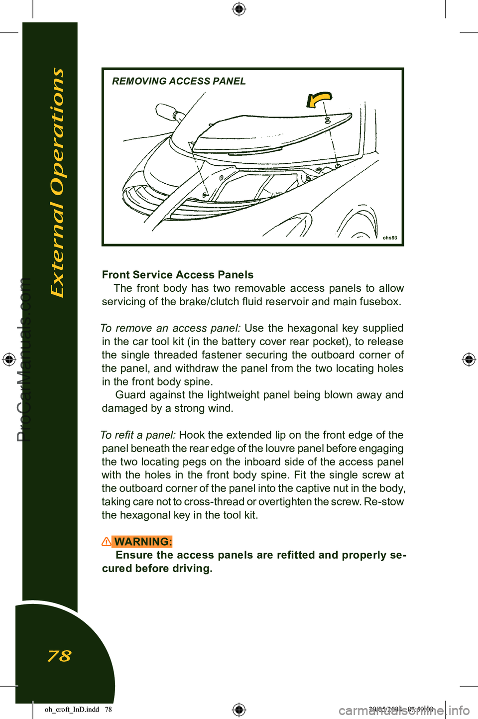
Front Service Access PanelsThe front body has two removable access panels to allow
servicing of the brake/clutch fluid reservoir and main fusebox.
To remove an access panel:
Use the hexagonal key supplied
in the car tool kit (in the battery cover rear pocket), to release
the single threaded fastener securing the outboard corner of
the panel, and withdraw the panel from the two locating holes in the front body spine. Guard against the lightweight panel being blown away and
damaged by a strong wind.
To refit a panel: Hook the extended lip on the front edge of the panel beneath the rear edge of the louvre panel before engaging
the two locating pegs on the inboard side of the access panel
with the holes in the front body spine. Fit the single screw at
the outboard corner of the panel into the captive nut in the body,
taking care not to cross-thread or overtighten the screw. Re-stow
the hexagonal key in the tool kit.
WARNING: Ensure the access panels are refitted and properly se
-
cured before driving.
External Operations
78
oh_croft_InD.indd 7820/05/2004 07:59:00ProCarManuals.com