set LOTUS ELISE 2005 User Guide
[x] Cancel search | Manufacturer: LOTUS, Model Year: 2005, Model line: ELISE, Model: LOTUS ELISE 2005Pages: 205, PDF Size: 4.51 MB
Page 74 of 205
STARTING PROCEDURE & ENGINE BREAK-IN
WARNING:CARBON MONOXIDE - Be aware of the danger of carbon
monoxide! Never run the engine in an enclosed space. The
exhaust gases contain carbon monoxide, a deadly gas
which is particularly dangerous, as being colourless odour
-
less and tasteless, its presence is very difficult to detect.
Before starting the engine, always check that the parking
brake is firmly applied, the transmission is in neutral, and as
an extra precaution, depress the clutch pedal. Switch off any
unnecessary electrical loads.
Starting a Cold or Warm Engine
The fuel injection and engine management system controls fuel delivery and engine settings under all normal operating conditions.
i) Insert the key into the steering lock/ignition switch and turn to
position ‘l’ to unlock the column. Before turning on the igni
-
tion; if the security tell tale in the tachometer face is flashing, mobilise the engine by pressing once, and for a full second,
the larger of the two buttons on the transmitter fob.
ii) Turn the key to position ‘II’ to switch on the ignition, and pause
for a moment to allow the fuel system to prime.
iii) Depress the clutch pedal as a precaution, and without moving
the accelerator, press the ‘Start’ button at the left hand end of
the dashboard to engage the starter motor. Release the button
as soon as the engine starts. Allow a cold engine to idle for
10 seconds before driving off, but if ambient temperatures are below freezing, allow the engine and screen heating systems
to warm up for a few minutes before driving.
iv) If the engine fails to start within 15 seconds, stop cranking
and pause for 10 seconds before a second attempt.
v) If further efforts are unsuccessful, contact your dealer or seek
other expert help.
WARNING:
An unattended car with a running engine is potentially
hazardous. Turn off the engine before leaving the car.
Starting & Engine Break-In
72
oh_croft_InD.indd 7220/05/2004 07:58:58ProCarManuals.com
Page 116 of 205
Auxiliary Drive BeltA single, multi-rib type auxiliary belt is used to transmit drive
from the crankshaft to the alternator, water pump, and (if fitted)
air conditioning compressor. The belt is automatically tensioned,
and requires no periodic maintenance other than a visual check of its condition. If the belt exhibits any evidence of physical dam
-
age, cracking, fraying, perishing, abrasion or contamination, it
should be renewed. In the case of contamination, the cause
must be identified and rectified, and each of the pulleys must be thoroughly degreased before the new belt is fitted. It is recommended that auxiliary belt replacement be en
-
trusted to your Lotus dealer.
Sparking Plugs The Elise uses a direct ignition system with an individual
high tension coil mounted atop each of the four spark plugs and protected by a plastic cover, screw fixed to the engine.
WARNING: The voltages produced with this ignition system can
cause serious and potentially fatal injur y. Never touch
any ignition components when the engine is running or being cranked.
The spark plugs should be renewed in accordance with the
Maintenance Schedule, with the gaps set to 0.043 in. (1.1 mm).
This operation should be entrusted to your Lotus dealer.
Servicing & Maintenance
114
oh_croft_InD.indd 11420/05/2004 07:59:09ProCarManuals.com
Page 121 of 205
handling feel and minimum steering wheel shake, it is very
important that the radial and lateral run out of the Tires are to the high standard required by Lotus Cars. If any difficulty is experienced with replacement Tires, refer to
the tire manufacturer.
Tire Characteristics The Yokohama AD07 or A048 Tires fitted to the Elise
are suitable for all normal weather conditions, but are optimised for dry road sports driving. The constructions
of both tire types have been specially tailored for the
Elise and are identified by the letters ‘LTS’ moulded on the tire sidewalls. Ensure that any replacement Tires are similarly marked. The tire characteristics include good
feedback (‘feel’) from the road surface to the steering
wheel, a high level of steering linearity and response, and little performance degradation with the high temperatures
which may be reached in sports use. However, tire performance will decrease at low ambi
-
ent temperatures, resulting in reduced levels of grip and
an increased susceptibility to damage from impacts. In
these conditions, especially below 15°F (-10°C), it is recommended to fit a car set of the recommended winter
Tires (see below).
Winter Tires If the car is to be used in ver y cold territories, or
driven on snow covered roads, it is recommended to fit a
car set of winter Tires developed specifically for such
conditions. Lotus approves the use of Pirelli 210 (front)
and 240 (rear) Snowsport winter Tires in sizes specified
in ‘Technical Data’. These Tires should be fitted on regular
Elise wheels.
WARNING:
• Winter Tires are optimised for use on snow covered roads. When used on roads free of snow, winter
Tires will produce different handling characteristics and less grip compared with regular Tires.
• When winter Tires are fitted, a maximum speed of 118 mph (190 km/h) must be observed.
• Pirelli Snowsport Tires are NOT suitable for stud
-
Tires & Wheels
119
oh_croft_InD.indd 11920/05/2004 07:59:10ProCarManuals.com
Page 129 of 205
Scheduled wheel alignment and balancing are not required.
However, if you notice unusual tire wear or the car pulling to one side or the other, the alignment may need to be reset. If
you notice the car or steering wheel vibrating when driving on a smooth road, the wheels may need to be re-balanced.
Wheel Replacement Replace any wheel that is bent, cracked, badly corroded or
otherwise damaged. If the wheel bolts come loose after having been correctly fitted, the wheel and bolts should be replaced.
If the wheel leaks air, have it replaced. See your Lotus dealer if any of these conditions should arise.
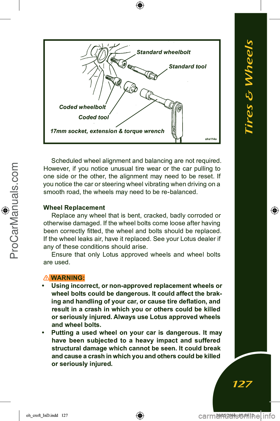
Ensure that only Lotus approved wheels and wheel bolts
are used.
WARNING:
• Using incorrect, or non-approved replacement wheels or wheel bolts could be dangerous. It could affect the brak
-
ing and handling of your car, or cause tire deflation, and result in a crash in which you or others could be killed
or seriously injured. Always use Lotus approved wheels
and wheel bolts.
• Putting a used wheel on your car is dangerous. It may have been subjected to a heavy impact and suffered
structural damage which cannot be seen. It could break
and cause a crash in which you and others could be killed
or seriously injured.
ohs114a
Coded wheelbolt
Coded tool
17mm socket, extension & torque wrench
Standard wheelbolt
Standard tool
Tires & Wheels
127
oh_croft_InD.indd 12720/05/2004 07:59:12ProCarManuals.com
Page 132 of 205
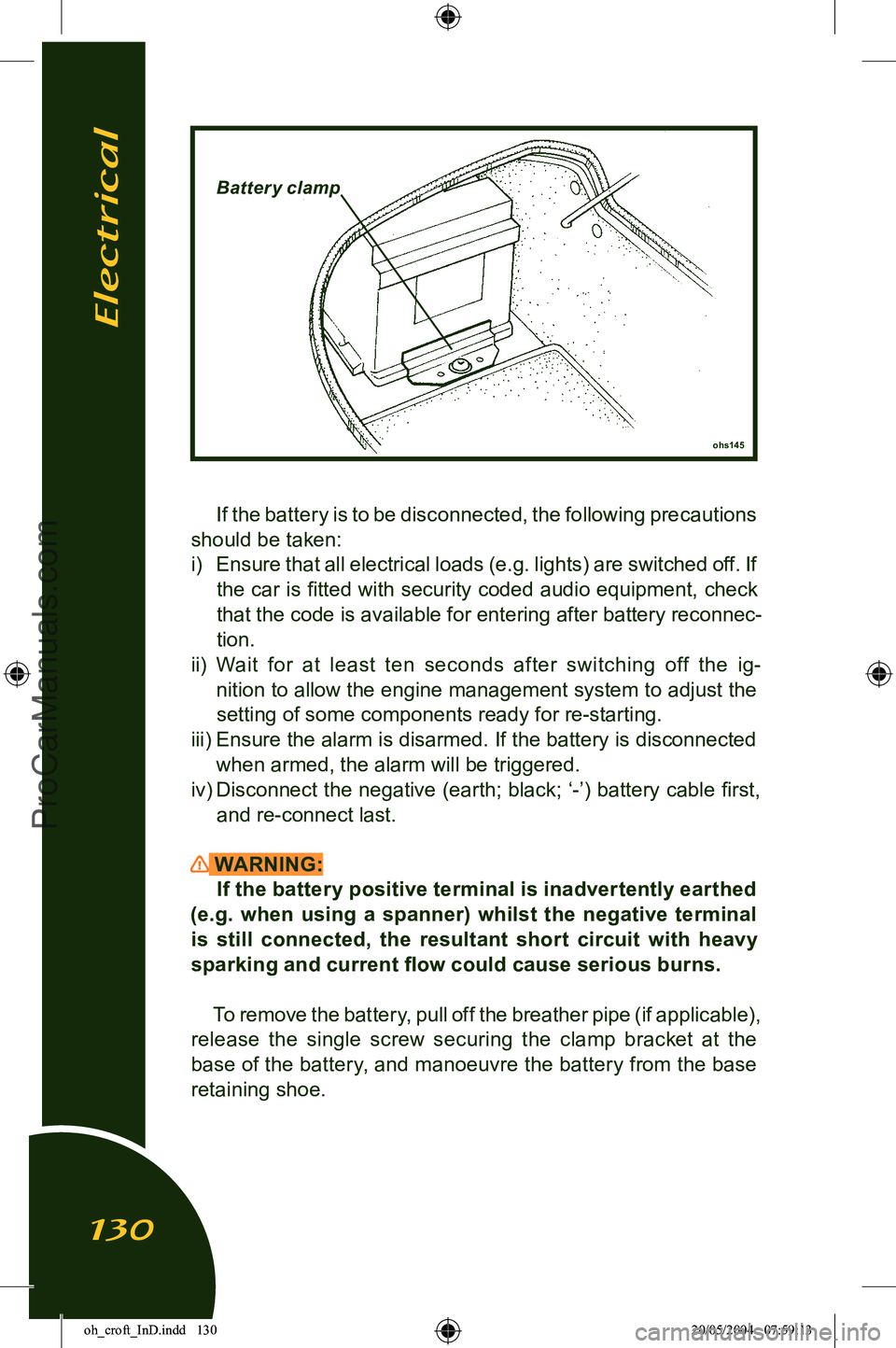
If the battery is to be disconnected, the following precautions
should be taken: i) Ensure that all electrical loads (e.g. lights) are switched off. If
the car is fitted with security coded audio equipment, check
that the code is available for entering after battery reconnec
-
tion.
ii) Wait for at least ten seconds after switching off the ig-
nition to allow the engine management system to adjust the
setting of some components ready for re-starting.
iii) Ensure the alarm is disarmed. If the battery is disconnected
when armed, the alarm will be triggered.
iv) Disconnect the
negative (earth; black; ‘-’) battery cable first,
and re-connect last.
WARNING:
If the battery positive terminal is inadvertently earthed
(e.g. when using a spanner) whilst the negative terminal
is still connected, the resultant short circuit with heavy sparking and current flow could cause serious burns.
To remove the battery, pull off the breather pipe (if applicable),
release the single screw securing the clamp bracket at the
base of the battery, and manoeuvre the battery from the base
retaining shoe.
ohs145
Batter y clamp
Electrical
130
oh_croft_InD.indd 13020/05/2004 07:59:13ProCarManuals.com
Page 133 of 205
WARNING:When lifting the battery out of, or into the car, be aware
of the considerable weight and take all appropriate precau
-
tions to safeguard personal health. Injury can result from improperly lifting the battery.
Keep the battery upright, and protect from sharp knocks
and shocks.
Reconnecting the Battery
WARNING: Failure to follow the correct battery re- connection pro
-
cedure detailed above could result in serious burns.
Refit the battery, with its terminals outboard, by reversing the
above procedure. Remember to push on the breather pipe (if
applicable), and reconnect the battery cables as detailed below.
Refit the battery cover.
i) Check again that all electrical loads are switched off.
ii) Connect the positive battery cable first, followed by the neg
-
ative (earth) cable.
iii) After reconnection, a change in the engine performance
characteristics may be noted for a period whilst the computer
controlled engine management system ‘re-learns’ some of its
settings.
iv) If necessary, enter the security code into audio equipment.
Battery Charging Under conditions of normal daily use, it should not be nec
-
essary to use external battery charging equipment. In a low usage regime, however, it is important to maintain the charge
state of the battery using a trickle charger, or an automatic bat
-
tery management conditioner such as that available through Lotus Dealers. Starting difficulties may be encountered after an
unattended period of 3 weeks. A battery conditioner is able to continuously monitor battery charge state and switch on and off automatically in order to maintain the battery in a fully charged
state without danger of damage through overcharging.
If the battery becomes discharged to the extent that the
car cannot be started, the recommended course of action is
to fit a substitute battery whilst the original battery is trickle
Electrical
131
oh_croft_InD.indd 13120/05/2004 07:59:13ProCarManuals.com
Page 137 of 205
WARNING:Inexper t modifications or additions to the electrical
system could jeopardise safety.
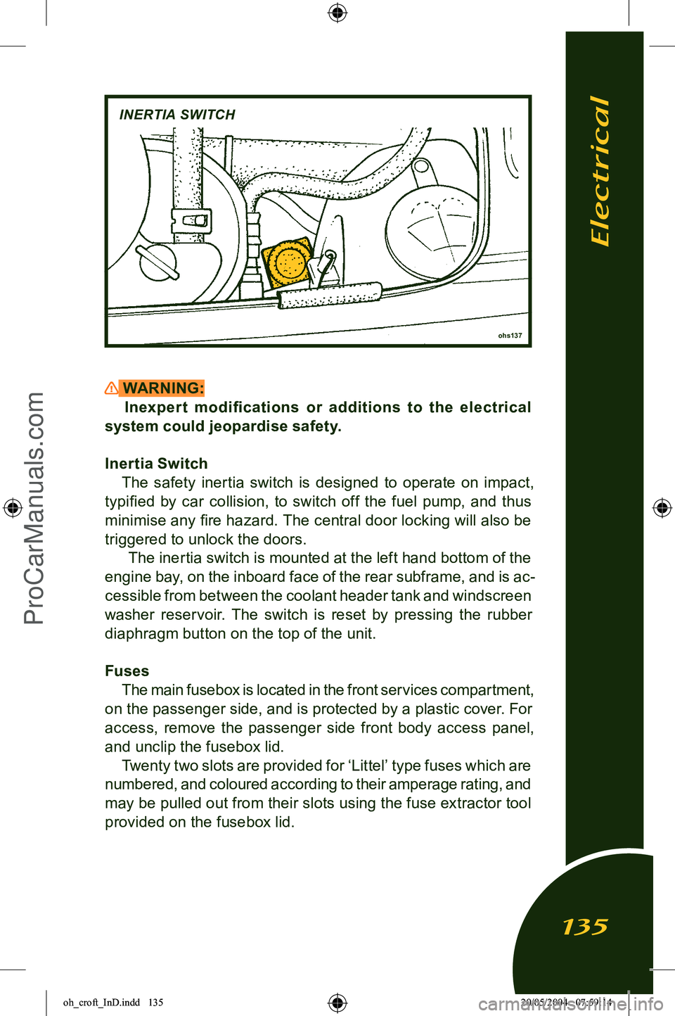
Inertia Switch The safety inertia switch is designed to operate on impact,
typified by car collision, to switch off the fuel pump, and thus
minimise any fire hazard. The central door locking will also be
triggered to unlock the doors. The inertia switch is mounted at the left hand bottom of the
engine bay, on the inboard face of the rear subframe, and is ac
-
cessible from between the coolant header tank and windscreen
washer reservoir. The switch is reset by pressing the rubber
diaphragm button on the top of the unit.
Fuses The main fusebox is located in the front services compartment,
on the passenger side, and is protected by a plastic cover. For
access, remove the passenger side front body access panel,
and unclip the fusebox lid. Twenty two slots are provided for ‘Littel’ type fuses which are
numbered, and coloured according to their amperage rating, and
may be pulled out from their slots using the fuse extractor tool provided on the fusebox lid.
ohs137
INERTIA SWITCH
Electrical
135
oh_croft_InD.indd 13520/05/2004 07:59:14ProCarManuals.com
Page 141 of 205
Headlamp AlignmentThe headlamps of your Elise were correctly adjusted during
the manufacture of the car, and should only require subsequent
adjustment if the headlamp assembly or front body is disturbed.
Simply replacing the bulb will not affect alignment. Incorrectly adjusted headlamps can cause poor lighting performance or dazzle to oncoming traf fic. Special headlamp setting equip
-
ment is required to correctly set the headlamps, such that only
qualified technicians using appropriate equipment should be
entrusted with this procedure:
1. Using beam setting equipment compatible with local regu
-
lations, position the machine between 300 and 700mm in
front of the LH headlamp, and parallel with the two headlamp
units using the sight bar or similar device dependent on the machine design, to ensure cross car match. Use the guides provided on the machine to ensure the correct height and
lateral setting.
2. Switch on the headlamp low beams (uppermost lamps) and check the lateral beam alignment. The ‘knee point’ of the beam cut off line must lie within a tolerance of 2% to the pas
-
senger side, and 0%. Check the vertical alignment of the low beam which must lie within a tolerance of - 0.5% and -2%.
Electrical
139
oh_croft_InD.indd 13920/05/2004 07:59:15ProCarManuals.com
Page 142 of 205
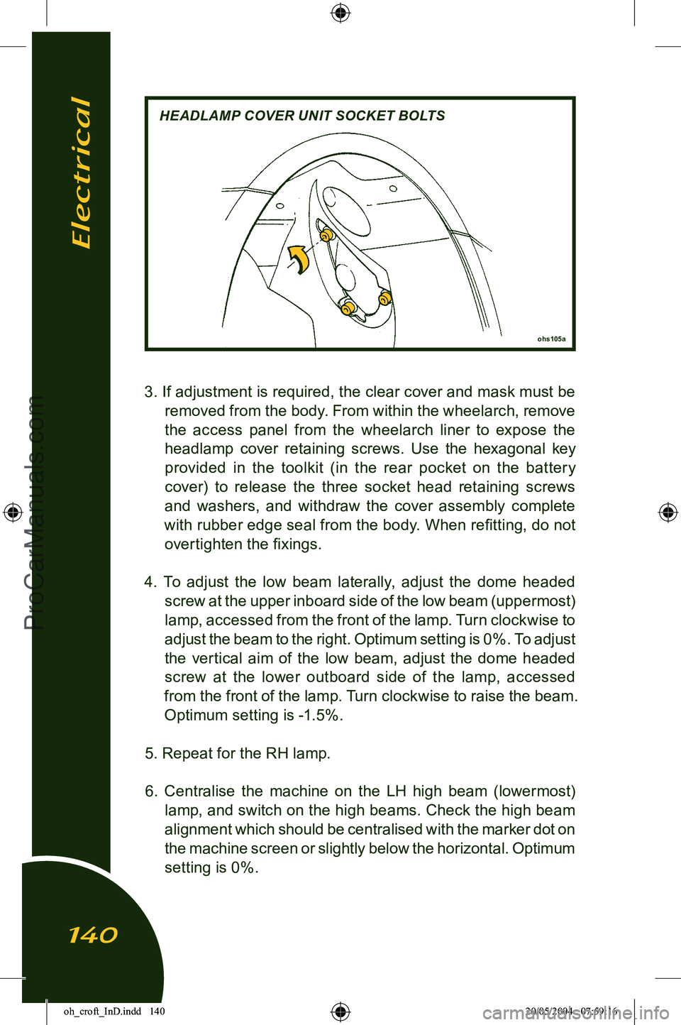
3. If adjustment is required, the clear cover and mask must be removed from the body. From within the wheelarch, remove
the access panel from the wheelarch liner to expose the
headlamp cover retaining screws. Use the hexagonal key provided in the toolkit (in the rear pocket on the batter y
cover) to release the three socket head retaining screws and washers, and withdraw the cover assembly complete
with rubber edge seal from the body. When refitting, do not overtighten the fixings.
4. To adjust the low beam laterally, adjust the dome headed screw at the upper inboard side of the low beam (uppermost)
lamp, accessed from the front of the lamp. Turn clockwise to
adjust the beam to the right. Optimum setting is 0%. To adjust
the vertical aim of the low beam, adjust the dome headed screw at the lower outboard side of the lamp, accessed
from the front of the lamp. Turn clockwise to raise the beam.
Optimum setting is -1.5%.
5. Repeat for the RH lamp. 6. Centralise the machine on the LH high beam (lowermost) lamp, and switch on the high beams. Check the high beam
alignment which should be centralised with the marker dot on
the machine screen or slightly below the horizontal. Optimum
setting is 0%.
ohs105a
HEADLAMP COVER UNIT SOCKET BOLTS
Electrical
140
oh_croft_InD.indd 14020/05/2004 07:59:16ProCarManuals.com
Page 164 of 205

LIMITED WARRANTYLotus Cars U.S.A. Inc.; 2236 Northmont Parkway, Duluth,
Georgia 30096.
LOTUS CARS U.S.A. Inc., (the Company) warrants each new
Lotus motor car sold by the Company or an authorised Lotus
dealer* in the U.S.A., and each Lotus replacement part supplied by the Company or an authorised Lotus dealer* in the U.S.A., to
be free from defects in material and workmanship under normal
use and service, and subject to the terms and conditions in this Limited Warranty, for the applicable Warranty Period set forth
in Paragraph 1. (*Authorised Lotus dealers are not owned by, or are agents of, the Company) The paragraphs below are the only and exclusive rem
-
edies under the terms of the warranty. The Limited Warranty excludes cer tain par ts and sets of
circumstances which are set out in section 4 below.
1. WARRANTY PERIODS
(a) LIMITED WARRANTY - Cars.
The Company warrants each new car to be free from defects
in material and workmanship for a period of thirty six (36) months or 36,000 miles, whichever first occurs, after the first
occurring of the following dates:
i) date of delivery of the car to the retail original owner;
ii) registration as a dealer demonstrator.
CONSULT YOUR SALES DOCUMENTS TO DETERMINE
THE WARR ANT Y START DATE ON YOUR CAR; SPE AK
TO YOUR DEALER OR LOTUS CARS USA IF YOU ARE IN DOUBT.
(b) LIMITED WARRANTY - Replacement Parts.
Genuine Lotus replacement parts are warranted to be free
from defects in materials and workmanship for 12 months
from the date of their installation or until the expiration of the
car’s limited warranty term, whichever occurs last.
Limited Warranty
162
oh_croft_InD.indd 16220/05/2004 07:59:20ProCarManuals.com