engine LOTUS ELISE 2005 Owner's Manual
[x] Cancel search | Manufacturer: LOTUS, Model Year: 2005, Model line: ELISE, Model: LOTUS ELISE 2005Pages: 205, PDF Size: 4.51 MB
Page 51 of 205
will also disable the engine coolant pump and result in rapid overheating; stop the engine as soon as it is safe to do so, and
summon assistance. If the drive belt is intact and the cooling
system unaffected, it may be possible in favourable daylight conditions, to drive a short distance to a repair facility, but do not, under any circumstances, allow the battery to become
completely discharged by continuing to drive.
Engine Malfunction Indicator Lamp
The engine Malfunction Indicator Lamp (MIL) is provided to
warn the driver that the engine management system has de
-
tected a fault which may result in increased noxious emissions from the exhaust. In order to minimise emissions and potential
engine damage, various operational limitations may automati
-
cally be applied. i) If the MIL lights continuously whilst driving, immediately reduce
speed and adopt a moderate driving style. Seek dealer advice
without delay and avoid all unnecessary journeys.
ii) If the MIL flashes, an engine misfire has been detected which is likely to cause overheat damage to the catalytic converter.
Slow down immediately and be prepared to stop.
- If the MIL then stops flashing, and is lit continuously, proceed with caution and seek dealer advice.
- If the MIL continues to flash, stop the car as soon as it is safe to do so, and switch off the engine. Seek dealer advice.
NOTICE:
Continuing to drive the car with a flashing MIL may
cause overheat damage to the catalytic converter, possible en
-
gine damage, increased emissions, and impaired fuel economy and driveability.
In order to comply with emissions regulations, data regarding
activation of the MIL is recorded in the engine electronic control
-
ler, and may be downloaded by Lotus dealers.
Security/RPM Tell Tale The security tell tale is located at the top of the tachometer
display, and indicates the status of the immobiliser and alarm.
• Tell tale out; engine is mobilised, and the alarm is off.
• Tell tale flashing; engine is immobilised, or alarm is armed
and engine immobilised.
For full details of the car security system, refer to the earlier
section ‘Car Security’.
Instruments & Switches
49
oh_croft_InD.indd 4920/05/2004 07:58:52ProCarManuals.com
Page 52 of 205
Note that the tell tale also functions as a high engine speed
(rpm) warning - see ‘Tachometer’.
NOTICE: The car is not fitted with a low pressure tell tale. You should check the tire condition and pressure regularly. See
section in the handbook on tires which specifies tire care and pressures.
Instruments & Switches
50
oh_croft_InD.indd 5020/05/2004 07:58:53ProCarManuals.com
Page 53 of 205
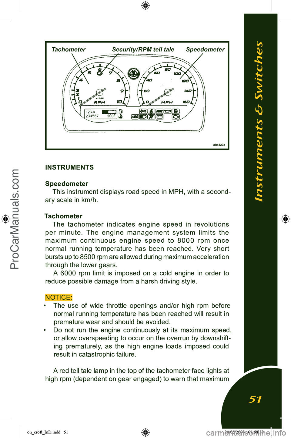
INSTRUMENTS
Speedometer This instrument displays road speed in MPH, with a second
-
ary scale in km/h.
Tachometer The t achometer indic ates engine speed in revolutions
p e r m i nu te. T h e e n g i n e m a n a g e m e nt sy s te m li m i t s t h e
m a x i m u m c o n t i n u o u s e n g i n e s p e e d t o 8 0 0 0 r p m o n c e
normal running temperature has been reached. Ver y shor t bursts up to 8500 rpm are allowed during maximum acceleration
through the lower gears. A 6000 rpm limit is imposed on a cold engine in order to
reduce possible damage from a harsh driving style.
NOTICE:
• The use of wide throttle openings and/or high rpm before
normal running temperature has been reached will result in
premature wear and should be avoided.
• Do not run the engine continuously at its maximum speed,
or allow overspeeding to occur on the overrun by downshift
-
ing prematurely, as the high engine loads imposed could
result in catastrophic failure.
A red tell tale lamp in the top of the tachometer face lights at
high rpm (dependent on gear engaged) to warn that maximum
Instruments & Switches
51
ohs127a
TachometerSecurity/ RPM tell taleSpeedometer
oh_croft_InD.indd 5120/05/2004 07:58:53ProCarManuals.com
Page 54 of 205
engine speed is being approached. When exploiting full accel-
eration, gearchange upshifts should be made immediately the
tell tale comes on.
Note that this lamp also functions as a security system tell
tale (see ‘Car Security’). Recalibration of the speedo and tacho needle zero positions
will occur during a 3 second period following ignition switch on,
but if a needle becomes ‘stranded‘ outside of the re-calibration
range, the following procedure should be followed:
With the car stationary;
• Open driver‘s door;
• Press and hold trip reset button on steering column shroud;
• Turn on ignition.
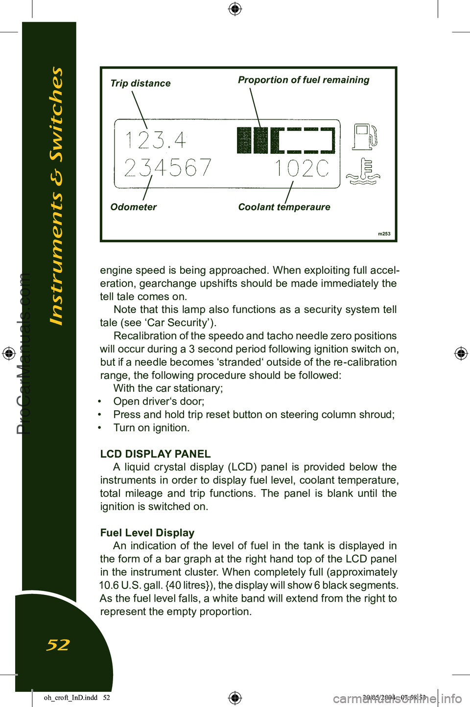
LCD DISPLAY PANEL A liquid crystal display (LCD) panel is provided below the
instruments in order to display fuel level, coolant temperature,
total mileage and trip functions. The panel is blank until the ignition is switched on.
Fuel Level Display An indication of the level of fuel in the tank is displayed in
the form of a bar graph at the right hand top of the LCD panel in the instrument cluster. When completely full (approximately
10.6 U.S. gall. {40 litres}), the display will show 6 black segments. As the fuel level falls, a white band will extend from the right to represent the empty proportion.
Instruments & Switches
52
m253
Trip distanceProportion of fuel remaining
Odometer Coolant temperaure
oh_croft_InD.indd 5220/05/2004 07:58:53ProCarManuals.com
Page 55 of 205
When only a single segment remains, representing approxi-
mately 1.3 U.S. gall. (5 litres), the amber low fuel tell tale will
flash. Refuel at the next opportunity.
NOTICE: Do not allow the tank to run completely dry, as this may damage the catalytic converter and fuel pump. This may
affect the terms of your warranty.
Coolant Temperature Display The engine coolant temperature will be displayed at the bot
-
tom right hand corner of the panel as soon as the temperature reaches 162°F. The running temperature will fluctuate a cer
-
tain amount as the operating conditions change, and during periods of idling or in heavy traffic, the temperature may rise to
over 212°F, with the cooling fans switching on at half speed at
approximately 208°F and at full speed at approximately 217°F.
The temperature display will flash at temperatures over 226°F to prompt closer monitoring by the driver of high temperatures.
The pressurised cooling system has a boiling point of over 248°F.
If the temperature approaches this level then the driver should be concerned. If this should occur, allow the engine to idle for a
few minutes whilst monitoring the temperature, and if it continues to rise, switch off and seek qualified assistance.
NOTICE: After a heavy snowfall, ensure that the radiator cooling
outlet grilles in the front body are cleared of snow before driving
the car, or overheating may occur.
Odometer An odometer (total distance recorder) reading is displayed at
the bottom left hand corner of the panel.
Trip Recorder A trip distance recorder is provided at the top left hand corner
of the panel. In order to zero the trip display, switch on the ignition, and
press for a moment (less than 1 second), the small button
on the steering column shroud ahead of the ignition switch.
This dual function button also controls the panel illumination
- see ‘Instrument & Switch Illumination’.
Instruments & Switches
53
oh_croft_InD.indd 5320/05/2004 07:58:53ProCarManuals.com
Page 63 of 205
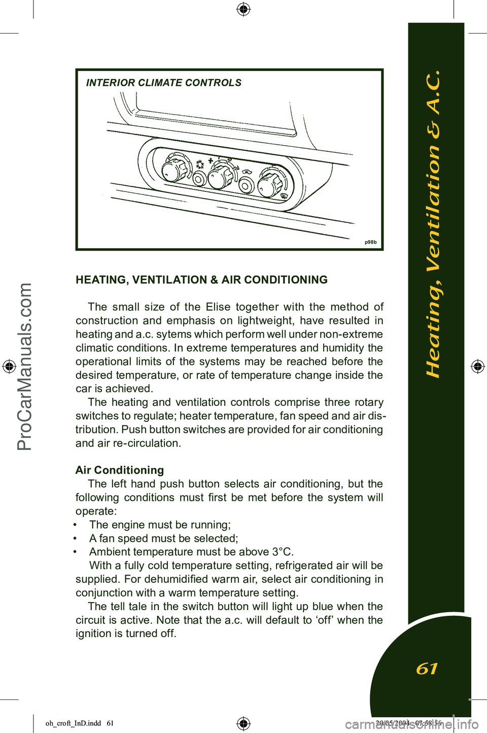
HEATING, VENTILATION & AIR CONDITIONINGThe small size of the Elise together with the method of
construction and emphasis on lightweight, have resulted in heating and a.c. sytems which perform well under non-extreme
climatic conditions. In extreme temperatures and humidity the operational limits of the systems may be reached before the
desired temperature, or rate of temperature change inside the
car is achieved. The heating and ventilation controls comprise three rotary
switches to regulate; heater temperature, fan speed and air dis
-
tribution. Push button switches are provided for air conditioning and air re-circulation.
Air Conditioning The left hand push button selects air conditioning, but the
following conditions must first be met before the system will
operate:
• The engine must be running;
• A fan speed must be selected;
• Ambient temperature must be above 3°C.
With a fully cold temperature setting, refrigerated air will be
supplied. For dehumidified warm air, select air conditioning in
conjunction with a warm temperature setting. The tell tale in the switch button will light up blue when the
circuit is active. Note that the a.c. will default to ‘off’ when the ignition is turned off.
Heating, Ventilation & A.C.
61
p 98b
INTERIOR CLIMATE CONTROLS
oh_croft_InD.indd 6120/05/2004 07:58:56ProCarManuals.com
Page 64 of 205
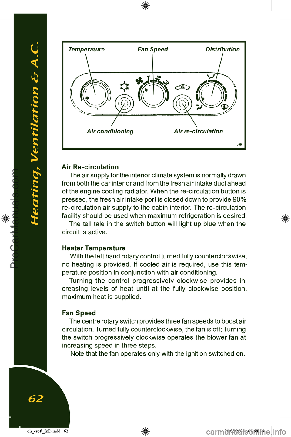
Air Re- circulation The air supply for the interior climate system is normally drawn
from both the car interior and from the fresh air intake duct ahead
of the engine cooling radiator. When the re-circulation button is pressed, the fresh air intake port is closed down to provide 90%
re-circulation air supply to the cabin interior. The re-circulation
facility should be used when maximum refrigeration is desired.
The tell tale in the switch button will light up blue when the
circuit is active.
Heater Temperature With the left hand rotary control turned fully counterclockwise,
no heating is provided. If cooled air is required, use this tem
-
perature position in conjunction with air conditioning. Turning the control progressively clock wise provides in
-
creasing levels of heat until at the fully clockwise position, maximum heat is supplied.
Fan Speed The centre rotary switch provides three fan speeds to boost air
circulation. Turned fully counterclockwise, the fan is off; Turning
the switch progressively clockwise operates the blower fan at increasing speed in three steps. Note that the fan operates only with the ignition switched on.
Heating, Ventilation & A.C.
62
p99
TemperatureFan SpeedDistribution
Air conditioning Air re-circulation
oh_croft_InD.indd 6220/05/2004 07:58:56ProCarManuals.com
Page 67 of 205
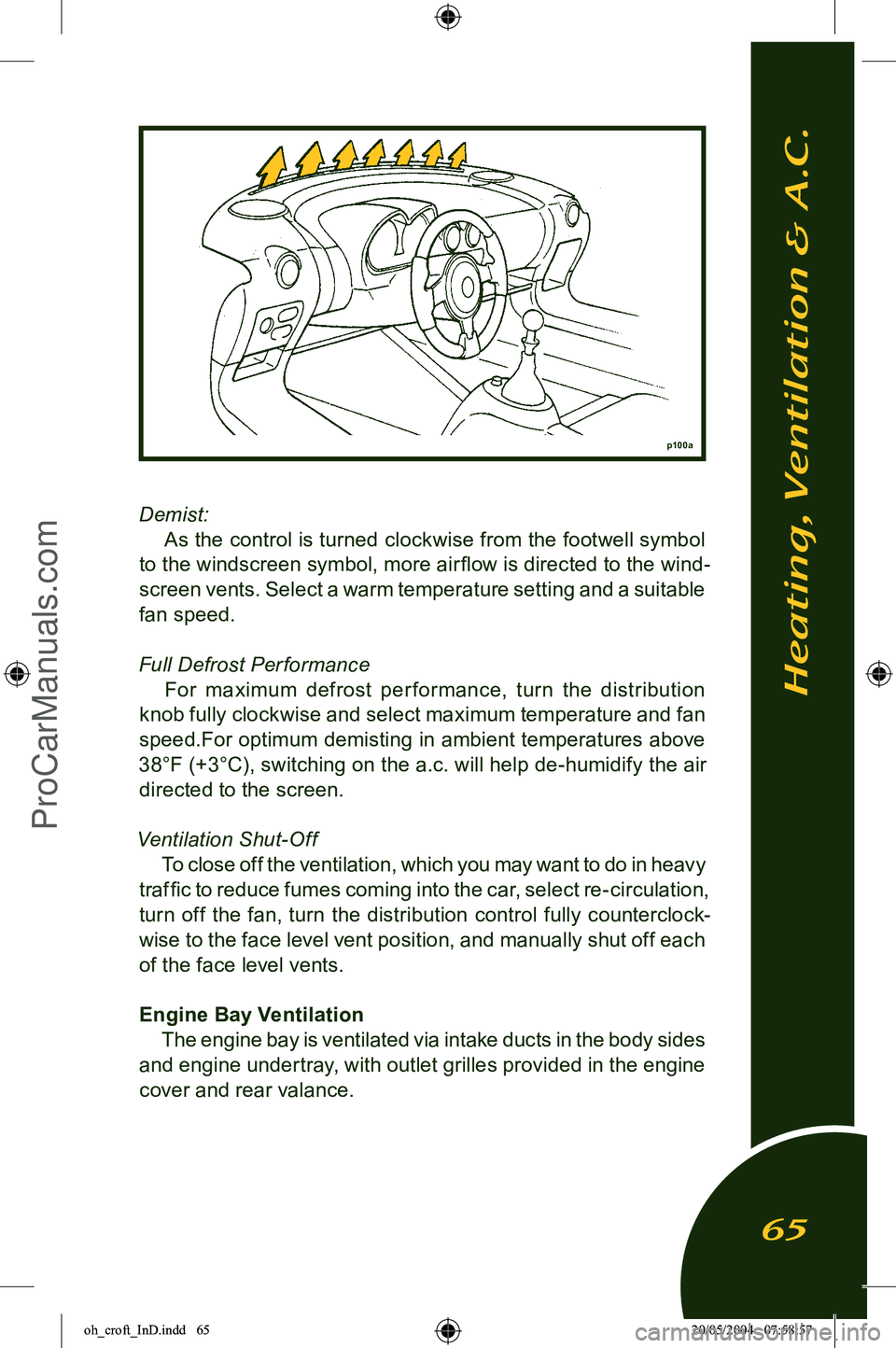
Demist:
As the control is turned clockwise from the footwell symbol
to the windscreen symbol, more air flow is directed to the wind
-
screen vents. Select a warm temperature setting and a suitable
fan speed.
Full Defrost Per formance For maximum defrost per formance, turn the distribution
knob fully clockwise and select maximum temperature and fan
speed.For optimum demisting in ambient temperatures above
38°F (+3°C), switching on the a.c. will help de-humidify the air directed to the screen.
Ventilation Shut-Off To close off the ventilation, which you may want to do in heavy
traffic to reduce fumes coming into the car, select re-circulation,
turn off the fan, turn the distribution control fully counterclock
-
wise to the face level vent position, and manually shut off each of the face level vents.
Engine Bay Ventilation The engine bay is ventilated via intake ducts in the body sides
and engine undertray, with outlet grilles provided in the engine
cover and rear valance.
p100a
Heating, Ventilation & A.C.
65
oh_croft_InD.indd 6520/05/2004 07:58:57ProCarManuals.com
Page 69 of 205
FootbrakeVentilated disc brakes are fitted to all four wheels of the
Elise. These are operated by separate front and rear hydraulic
circuits, supplied from a tandem master cylinder with vacuum
servo. Anti-lock control is provided by a microprocessor based
electro-hydraulic unit, integrated into the base braking system. The braking system is designed to provide good pedal feed
-
back, with efficient disc cooling to inhibit brake fade. With a
new car, or new brake system components, maximum braking
efficiency will be achieved if, for the first few hundred miles, needless heavy braking is avoided. Allow the brake pads and discs to ‘bed in’ fully before using the brakes to their full potential.
Pedal effort will reduce as the brakes are bedded in, and as they
are warmed from cold to normal working temperature. Note that
the hard grade pad material may give rise to a certain amount of brake noise under some conditions; such noise is not harmful
and does not affect the life or efficiency of the brakes.
WARNING:
• After driving through a ford, or a flooded road, some loss of braking response may be experienced until the brakes
have dried out. As soon as it is safe to do so after such an encounter, apply the brakes until normal operation
is restored. Failure to do so may result in an accident in
which you or others may be killed or seriously injured.
• The brake assistance servo uses vacuum supplied from the engine intake plenum, such that assistance is avail
-
able only when the engine is running. Never coast down
-
hill with the engine stopped. If this situation accidently arises, avoid repeated application of the brakes, or the
stored vacuum supply will be rapidly used up. Greater
pedal pressures will be required. This may adversely affect performance of the brakes which may result in an
accident in which you or others may be killed or seriously
injured.
Anti-lock Brake System The Anti-lock Brake System (ABS) is used to optimise brake
performance in extreme conditions and reduce the potential
for any wheel to lock up. Under most conditions, the maximum braking force is provided by a wheel which is rotating at about
90% of road speed. Apart from the likelihood of increasing the
Driving Controls
67
oh_croft_InD.indd 6720/05/2004 07:58:57ProCarManuals.com
Page 73 of 205
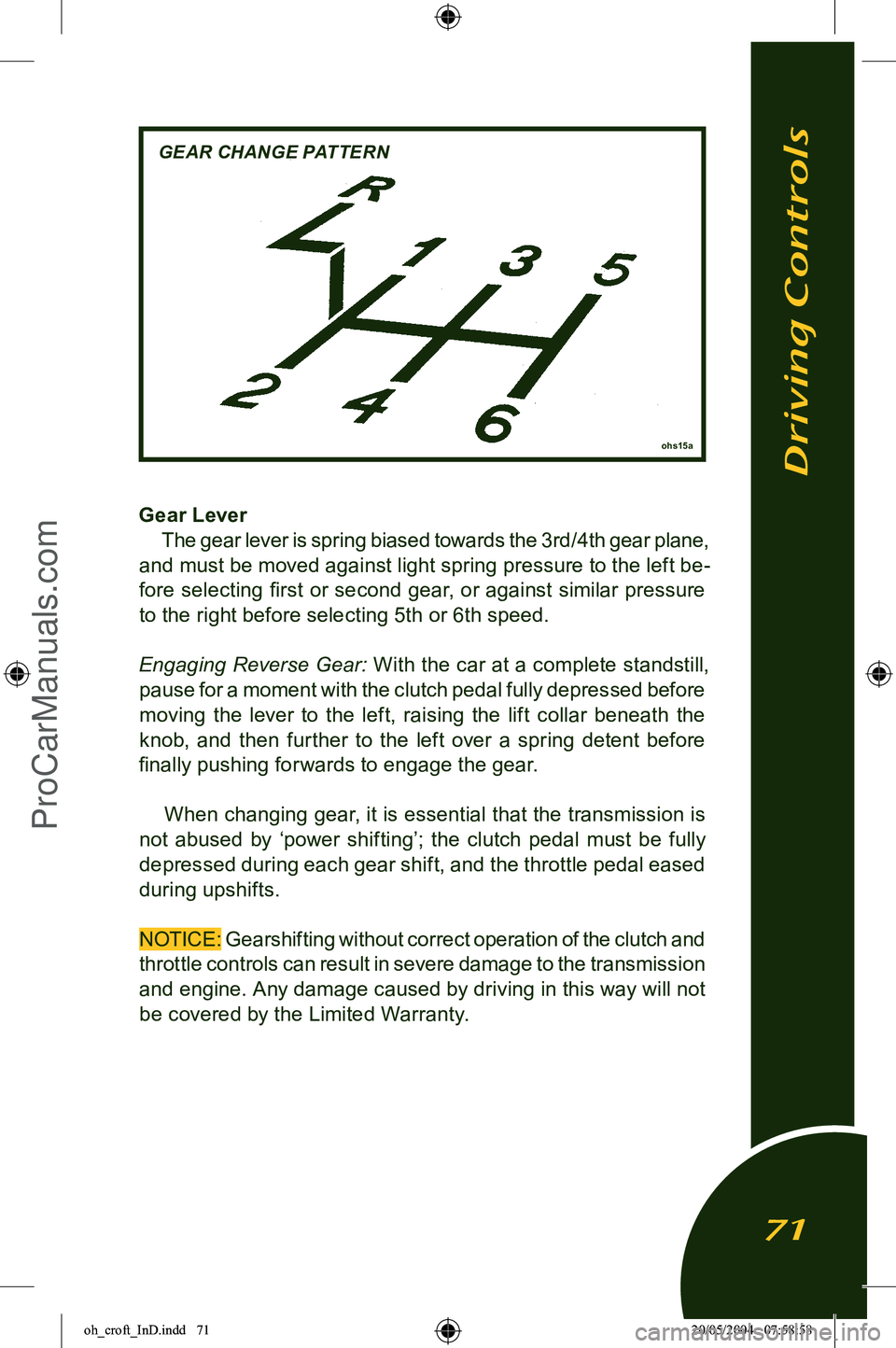
Gear LeverThe gear lever is spring biased towards the 3rd/4th gear plane,
and must be moved against light spring pressure to the left be
-
fore selecting first or second gear, or against similar pressure to the right before selecting 5th or 6th speed.
Engaging Reverse Gear: With the car at a complete standstill
,
pause for a moment with the clutch pedal fully depressed before
moving the lever to the left, raising the lift collar beneath the
knob, and then further to the left over a spring detent before
finally pushing forwards to engage the gear.
When changing gear, it is essential that the transmission is
not abused by ‘power shifting’; the clutch pedal must be fully
depressed during each gear shift, and the throttle pedal eased
during upshifts.
NOTICE: Gearshifting without correct operation of the clutch and
throttle controls can result in severe damage to the transmission
and engine. Any damage caused by driving in this way will not be covered by the Limited Warranty.
Driving Controls
71
ohs15a
GEAR CHANGE PATTERN
oh_croft_InD.indd 7120/05/2004 07:58:58ProCarManuals.com