ECO mode MASERATI GHIBLI 2019 User Guide
[x] Cancel search | Manufacturer: MASERATI, Model Year: 2019, Model line: GHIBLI, Model: MASERATI GHIBLI 2019Pages: 384, PDF Size: 13.33 MB
Page 88 of 384
system checked by the Authorized
Maserati Dealer .
WARNING!
Certain components of this vehicle
such as air bag modules, seat belt
pretensioners, adaptive steering
columns, and button cell batteries may
contain Perchlorate material. Special
handling may apply for service or
vehicle end of life disposal. See
www.dtsc.ca.gov/hazardouswaste/
perchlorate.
Defroster
Check
operation by
selecting the
defrost mode and place the fan system
on high speed (see “Air Conditioning
Controls” chapter in section
“Dashboard Instruments and
Controls”).
You should be able to feel the air
directed against the windshield and
front side windows. Contact
Authorized Maserati Dealer for service
if your defroster is inoperable.
Floor Mat
Always use floor mats designed to fit
the footwell of your vehicle. Use only
floor mats that leave the pedal area
unobstructed and that are firmly secured so that they cannot slip out of
position and interfere with the pedals
or impair safe operation of your
vehicle.
NOTE:
The Authorized Maserati Dealer can
provide you with any information
about the available Maserati floor
mats included in the “Genuine
Accessories” range.
WARNING!
Pedals that cannot move freely can
cause loss of vehicle control and
increase the risk of serious personal
injury.
• Always make sure that floor mats
are properly attached to the proper
fasteners.
• Never place or install floor mats or
other floor coverings in the vehicle
that cannot be properly secured to
prevent them from moving and
interfering with the pedals.
• Never put floor mats or other floor
coverings on top of already installed
floor mats. Additional floor mats and
other coverings will reduce the size
of the pedal area and interfere with the pedals.
• Check mounting of mats on a regular
basis. Always properly reinstall and
secure floor mats that have been
removed for cleaning.
• Always make sure that objects
cannot fall into the driver footwell
while the vehicle is moving. Objects
can become trapped under the brake
pedal and accelerator pedal causing
a loss of vehicle control.
• Mounting posts must be properly
installed, if not equipped from the
factory. Failure to properly follow
floor mat installation or mounting
can cause interference with the
brake pedal and accelerator pedal
operation causing loss of control of
the vehicle.
Tires
•
Examine tires for excessive tread
wear and uneven wear patterns.
• Check for stones, nails, glass, or other
objects lodged in the tread or
sidewall.
• Inspect the tread for cuts and cracks.
• Inspect sidewalls for cuts, cracks and
bulges.
• Check the wheel nuts for tightness.Before Starting
2
84
Page 116 of 384
Automatic Headlights This system automatically turns the
headlights on or off according to
ambient light intensity detected by the
twilight sensor positioned on the inner
surface of the windshield, over the
rear view mirror. To turn the system
on, rotate the lights switch clockwise
to “AUTO” position.
When the automatic system is
activated, the headlight time delay
feature is activated as well. This means
the headlights will stay on for up to 90
seconds after you place the ignition
device into OFF position.
To turn the automatic system off,
move the lights switch out of “AUTO”
position.
NOTE:
The engine must be running before
the headlights turn on in automatic
mode.
WARNING!
The responsibility for turning on the
lights, depending on the daylight and
regulations in force in the country of
use, always lies with the driver. The
automatic system for switching on
and off the external lights is to be considered as an aid for the driver. If
necessary, switch the lights including
the rear fog lights on and off
manually.
Headlights On with Wipers
When
this feature
is active, the
headlights will turn on approximately
10 seconds after activation of the
wipers, if the lights switch is placed in
the “AUTO” position. The headlights
will additionally turn off by
deactivation of the wipers if previously
activated with this function.
NOTE:
The headlights with wipers feature
may be turned on and off using the
MTC+ System, refer to “MTC+
Settings” in section “Dashboard
Instruments and Controls”.
Headlights Time Delay This safety feature provides headlight
illumination for up to 90 seconds
(programmable) when leaving your
vehicle in an unlit area. To activate the
delay feature, place the ignition switch
in the OFF or ACC position while the
headlights are still on. Then turn off
the headlights within 45 seconds. The delay interval begins when the
lights switch is turned off (position
“0”). If you turn the headlights or
position lights on, or place the ignition
switch in RUN , the system will cancel
the delay.
If you turn the headlights off (“0”
position) before the ignition, they will
turn off in the normal mode.
NOTE:
• To activate this feature the lights
must be turned off (“0” position)
within 45 seconds of placing the
ignition switch in the OFF or ACC
position.
• Once the delay feature is active, any
additional shifting of the light switch
will cancel the feature.
• The headlight delay time is
programmable using the MTC+
System, see “MTC+ Settings” in
section “Dashboard Instruments and
Controls”.
• If the low beam bulbs/LEDs are active
due to “Headlights with Wipers”,
then the headlamps delay feature
will not be activated when the
ignition switch is set in OFF position.Understanding the Vehicle
3
112
Page 117 of 384
Daytime Running Lights (DRL) The lighting system uses the same
high or low intensity headlamps LED,
respectively, for the DRL lights and
front position lights.
DRL lights will turn on when the
twilight sensor is in “DAY” mode, the
engine is running and the light switch
is in
or “AUTO” position.
If a turn signal is activated, the DRL
LED on the same side of the vehicle
switches in position light function for
the duration of the turn signal
activation. Once the turn signal is
deactivated, the DRL LED will light up
again.
NOTE:
On Canadian vehicles DRL are always
on. On USA vehicles, the DRL lights
can be turned on and off using the
MTC+ System, see “MTC+ Settings” in
section “Dashboard Instruments and
Controls” for further information.
Bi-Xenon Headlight The gas-discharge (xenon) headlights
operate with an electric arc saturated
with Xenon gas under pressure,
instead of the incandescent filament.
The light produced is assuredly higher
compared to traditional light bulbs, in terms of quality (brighter light) as well
as of the span and positioning of the
illuminated area.
WARNING!
If xenon headlamp replacement is
necessary, contact the Authorized
Maserati Dealer only: DANGER - RISK
OF ELECTRICAL SHOCK.
“Full-LED” Headlight with
Cornering Function These headlamps combine the
cornering function to the “Full-LED”
technology consisting of an additional
LED module which turns on when two
conditions occurs: the driver turns the
steering wheel or the driver activates
the turn indicator. The cornering
function will illuminate the corner to
enhance the visibility to the driver as
long as speed will be lower than 25
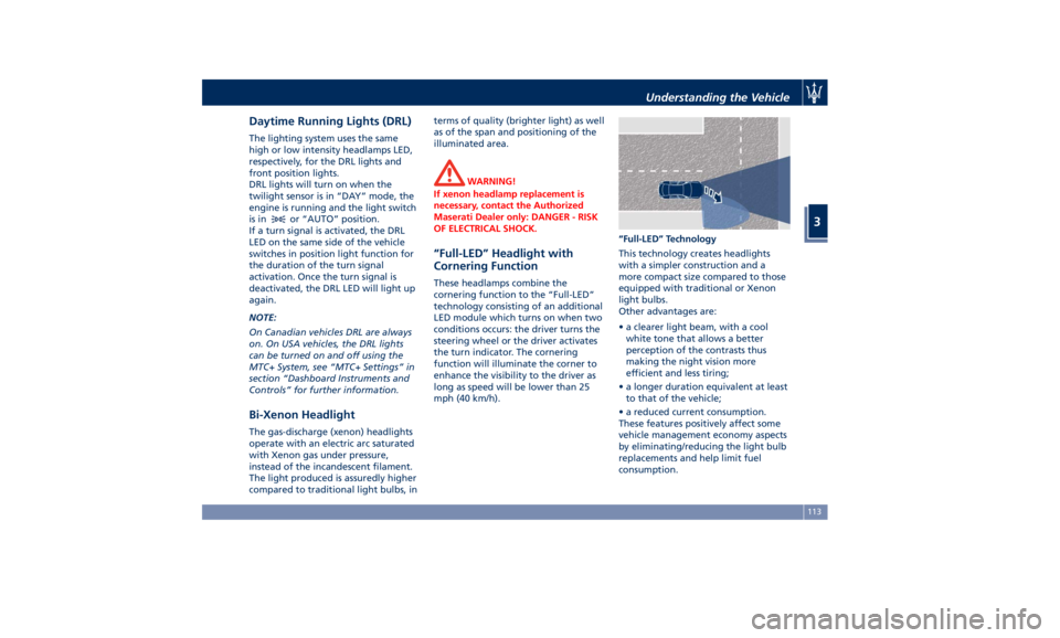
mph (40 km/h). “Full-LED” Technology
This technology creates headlights
with a simpler construction and a
more compact size compared to those
equipped with traditional or Xenon
light bulbs.
Other advantages are:
• a clearer light beam, with a cool
white tone that allows a better
perception of the contrasts thus
making the night vision more
efficient and less tiring;
• a longer duration equivalent at least
to that of the vehicle;
• a reduced current consumption.
These features positively affect some
vehicle management economy aspects
by eliminating/reducing the light bulb
replacements and help limit fuel
consumption.Understanding the Vehicle
3
113
Page 118 of 384

Automatic High Beam (for
versions/markets, where
provided) The Automatic High Beam headlight
control system provides increased
forward lighting at night by
automating high beam control
through the use of the forward-facing
digital camera located behind the
rear-view mirror, which is the same
one used for example by the Lane
Keeping Assist - LKA system on vehicles
with ADAS systems.
This camera detects the environmental
luminosity, the headlamps of
oncoming vehicles and the tail lamps
of proceding vehicles in the front area.
In these cases, the system
automatically switches from high
beams to low beams until the
approaching vehicle is out of view.
Futhermore, the digital camera is able
to detect the urban areas and the
inhabited centers and to turn off the
high beams when driving near of one
of them.
The properly working for this feature
(if all the other conditions are met) is
ensured between 21.7 mph (35 km/h)
and 155 mph (250 km/h). Activation Mode
To activate Automatic High Beam
feature:
• Shift the multifunction lever onward
.
• Put the light switch in “AUTO”
position.
• Touch the “Controls” soft-key in the
lower part of the MTC+ display.
• Within 15 seconds, touch the "Auto
High Beam Assist" soft-key to turn
on the feature. • Within 15 seconds, touch the "Auto
High Beam Assist" soft-key a second
time to turn it off.
After these steps, the green indicator
on the upper right side of the TFT
display comes on.
Without ADAS With ADASUnderstanding the Vehicle
3
114
Page 136 of 384
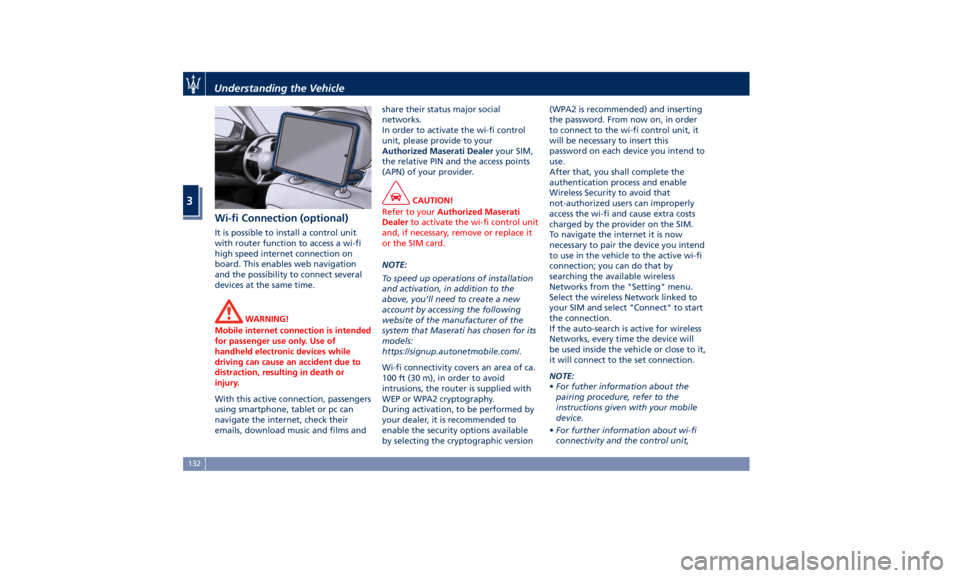
Wi-fi Connection (optional) It is possible to install a control unit
with router function to access a wi-fi
high speed internet connection on
board. This enables web navigation
and the possibility to connect several
devices at the same time.
WARNING!
Mobile internet connection is intended
for passenger use only. Use of
handheld electronic devices while
driving can cause an accident due to
distraction, resulting in death or
injury.
With this active connection, passengers
using
smartphone, tablet
or pc can
navigate the internet, check their
emails, download music and films and share their status major social
networks.
In order to activate the wi-fi control
unit, please provide to your
Authorized Maserati Dealer your SIM,
the relative PIN and the access points
(APN) of your provider.
CAUTION!
Refer to your Authorized Maserati
Dealer to activate the wi-fi control unit
and, if necessary, remove or replace it
or the SIM card.
NOTE:
T
o speed up operations of installation
and activation, in addition to the
above, you’ll need to create a new
account by accessing the following
website of the manufacturer of the
system that Maserati has chosen for its
models:
https://signup.autonetmobile.com/.
Wi-fi connectivity covers an area of ca.
100 ft (30 m), in order to avoid
intrusions, the router is supplied with
WEP or WPA2 cryptography.
During activation, to be performed by
your dealer, it is recommended to
enable the security options available
by selecting the cryptographic version (WPA2 is recommended) and inserting
the password. From now on, in order
to connect to the wi-fi control unit, it
will be necessary to insert this
password on each device you intend to
use.
After that, you shall complete the
authentication process and enable
Wireless Security to avoid that
not-authorized users can improperly
access the wi-fi and cause extra costs
charged by the provider on the SIM.
To navigate the internet it is now
necessary to pair the device you intend
to use in the vehicle to the active wi-fi
connection; you can do that by
searching the available wireless
Networks from the "Setting" menu.
Select the wireless Network linked to
your SIM and select "Connect" to start
the connection.
If the auto-search is active for wireless
Networks, every time the device will
be used inside the vehicle or close to it,
it will connect to the set connection.
NOTE:
• For futher information about the
pairing procedure, refer to the
instructions given with your mobile
device.
• For further information about wi-fi
connectivity and the control unit,Understanding the Vehicle
3
132
Page 141 of 384
• In a collision, there is a greater risk
of being thrown from the vehicle if
the sunroof is open. Always fasten
your seat belt properly and make
sure all passengers are properly
secured too.
• Do not allow small children to
operate the sunroof. Never insert
fingers, other body parts, or any
object through the opening sunroof.
CAUTION!
• In the event of rain, always close the
sunroof to prevent water
infiltrations from staining the
fabric/leather upholstery.
• Do not open the sunroof if there is
ice on it: risk of damage.
Slide Opening Sunroof • Full automatic express opening
Press the right rear button for more
than half second and the sunroof
will open automatically regardless
of any previous position. The
sunroof will open fully and stop
automatically. During this
operation, if any sunroof button is
pressed, the sunroof will stop. • Full or partial manual opening
To open the sunroof manually press
the right rear button for less than
half second to move step by step
the sunroof panel.
Venting Sunroof Press and release the left button, and
the sunroof will open to the vent
position. This is called “Express Vent”,
and will occur regardless of sunroof
position. During this opening
operation, any movement of the
button will stop the sunroof.
Pinch Protect Feature This feature will detect an obstruction
in the opening of the sunroof during
express close operation. If an
obstruction is detected, the sunroof
will automatically retract. If this
occurs, remove the obstruction then
press the right front button and
release to express close.
NOTE:
If three consecutive attempts to close
in express mode the sunroof result in
pinch protect reversals, the fourth
attempt will be manual, with pinch
protect feature disabled. Pinch Protect Override
If any obstruction (ice, debris, etc.)
prevents closing the sunroof, press the
right front button and hold for two
seconds after the reversal occurs. This
allows the sunroof to move toward
the closed position.
NOTE:
Pinch protection is disabled while
pressing the right front button.
Wind Buffeting Wind buffeting can be described as
the perception of pressure or a
helicopter-type sound. Your vehicle
may exhibit wind buffeting with the
windows down, or the sunroof in
certain open or partially open
positions. This is a normal occurrence
and can be minimised. If the buffeting
occurs with the rear windows open,
then open the front and rear windows
together to minimise the buffeting. If
the buffeting occurs with the sunroof
open, then adjust the sunroof opening
to minimise the buffeting.
Ignition Off Operation The power sunroof controls will
remain active for up to approximately
ten minutes after the ignition switch isUnderstanding the Vehicle
3
137
Page 144 of 384
NOTE:
The distance necessary between the
portable hand-held transmitter and
the HomeLink ®
in the vehicle depends
on the system you wish to program.
Probably it will be necessary to try
several times. Upon every attempt,
keep the setting position for at least
15 seconds before trying again.
Synchronizing the Rolling Codes
At the end of the previously-described
programming, if the HomeLink ®
has
been programmed for a rolling code
system, it will be necessary to
synchronize it to ensure its correct
operation.
• Locate the “LEARN” or “TRAINING”
setting button of the opening motor.
Firmly press it and then release it. On
some garage door openers/devices
there may be a light that blinks
when the garage door opener/device
is in the LEARN/TRAIN mode.
NOTE:
You have 30 seconds to initiate the
next step after the setting button has
been pressed. • Return to the vehicle and press the
programmed HomeLink ®
button for
two seconds and then release it.
• Repeat this operation a second time.
If the garage door opening device
activates, the programming/
synchronization phase is complete.
NOTE:
If the garage door opening device
does not activate, press the button a
third time for two seconds and then
release it to complete the
programming/synchronization phase.
• To program the remaining two
HomeLink ®
buttons, repeat each step
for each remaining button. DO NOT
erase the channels.
Reprogramming a Single HomeLink ®
Button
To reprogram a channel that has been
previously trained, follow these steps:
• Place the ignition device to the RUN
position without starting the engine.
• Press and hold the desired
HomeLink ®
button.
• Without releasing the button
proceed with “Programming the
hand-held transmitters” from second
step and follow all remaining steps. System with Devices Without
Rolling Code Programming the Hand-held
Transmitters
Programming garage door openers
manufactured before 1995.
• Turn the ignition device to the RUN
position without starting the engine.
• Place the hand-held transmitter 1 to
3 inches (5 to 30 cm) away from the
HomeLink ®
button you wish to
program.
• Simultaneously press and hold both
buttons until the indicator light
starts flashing quickly; then release
both buttons.
The quick flashing light indicates that
the channel with the new frequency
has been acquired and programmed
correctly by the HomeLink ®
system.
NOTE:
The distance necessary between the
portable hand-held transmitter and
the HomeLink ®
in the vehicle depends
on the system you wish to program.
Probably it will be necessary to try
several times. Upon every attempt,
keep the setting position for at least
15 seconds before trying again.Understanding the Vehicle
3
140
Page 150 of 384
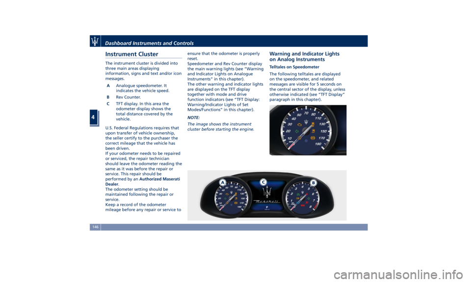
Instrument Cluster The instrument cluster is divided into
three main areas displaying
information, signs and text and/or icon
messages.
A Analogue speedometer. It
indicates the vehicle speed.
B Rev Counter.
C TFT display. In this area the
odometer display shows the
total distance covered by the
vehicle.
U.S. Federal Regulations requires that
upon transfer of vehicle ownership,
the seller certify to the purchaser the
correct mileage that the vehicle has
been driven.
If your odometer needs to be repaired
or serviced, the repair technician
should leave the odometer reading the
same as it was before the repair or
service. This repair should be
performed by an Authorized Maserati
Dealer .
The odometer setting should be
maintained following the repair or
service.
Keep a record of the odometer
mileage before any repair or service to ensure that the odometer is properly
reset.
Speedometer and Rev Counter display
the main warning lights (see “Warning
and Indicator Lights on Analogue
Instruments” in this chapter).
The other warning and indicator lights
are displayed on the TFT display
together with mode and drive
function indicators (see “TFT Display:
Warning/Indicator Lights of Set
Modes/Functions” in this chapter).
NOTE:
The image shows the instrument
cluster before starting the engine. Warning and Indicator Lights
on Analog Instruments Telltales on Speedometer
The following telltales are displayed
on the speedometer, and related
messages are visible for 5 seconds on
the central sector of the display, unless
otherwise indicated (see “TFT Display”
paragraph in this chapter).Dashboard Instruments and Controls
4
146
Page 155 of 384
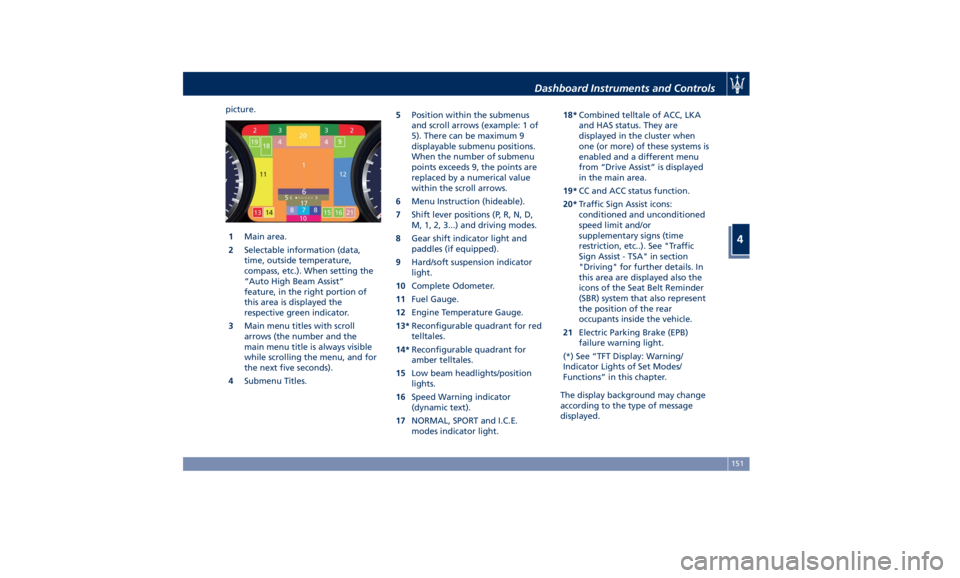
picture.
1 Main area.
2 Selectable information (data,
time, outside temperature,
compass, etc.). When setting the
“Auto High Beam Assist”
feature, in the right portion of
this area is displayed the
respective green indicator.
3 Main menu titles with scroll
arrows (the number and the
main menu title is always visible
while scrolling the menu, and for
the next five seconds).
4 Submenu Titles. 5 Position within the submenus
and scroll arrows (example: 1 of
5). There can be maximum 9
displayable submenu positions.
When the number of submenu
points exceeds 9, the points are
replaced by a numerical value
within the scroll arrows.
6 Menu Instruction (hideable).
7 Shift lever positions (P, R, N, D,
M, 1, 2, 3...) and driving modes.
8 Gear shift indicator light and
paddles (if equipped).
9 Hard/soft suspension indicator
light.
10 Complete Odometer.
11 Fuel Gauge.
12 Engine Temperature Gauge.
13* Reconfigurable quadrant for red
telltales.
14* Reconfigurable quadrant for
amber telltales.
15 Low beam headlights/position
lights.
16 Speed Warning indicator
(dynamic text).
17 NORMAL, SPORT and I.C.E.
modes indicator light. 18* Combined telltale of ACC, LKA
and HAS status. They are
displayed in the cluster when
one (or more) of these systems is
enabled and a different menu
from “Drive Assist” is displayed
in the main area.
19* CC and ACC status function.
20* Traffic Sign Assist icons:
conditioned and unconditioned
speed limit and/or
supplementary signs (time
restriction, etc..). See "Traffic
Sign Assist - TSA" in section
"Driving" for further details. In
this area are displayed also the
icons of the Seat Belt Reminder
(SBR) system that also represent
the position of the rear
occupants inside the vehicle.
21 Electric Parking Brake (EPB)
failure warning light.
(*) See “TFT Display: Warning/
Indicator Lights of Set Modes/
Functions” in this chapter.
The display background may change
according to the type of message
displayed.Dashboard Instruments and Controls
4
151
Page 157 of 384
Main Menu & Submenu Content
Overview
1. MAIN MENU
• View speed in mph or km/h
2. VEHICLE INFO
• Tire Pressure
• Transmission Temperature
• Oil Temperature
• Oil Pressure
• Battery Voltage
• Maintenance
3. DRIVE MODE
• Drive Mode - Torque Distribution (on
AWD version only) - Powertrain
status - ESC status - Suspension
stiffness status
4. Driver Assist (if equipped)
• Shows the status of any active driver
assist systems: CC, ACC, LKA and
HAS. Graphics in the main area of
TFT display only refer to ACC, LKA
and HAS systems
• LKA (LaneSense) status
5. FUEL ECONOMY
• Average, Range, Current gage
6. TRIP
• Trip A: Average, Avg. speed, Elapsed
time, Distance • Trip B: Average, Avg. speed, Elapsed
time, Distance
7. START&STOP
• Messages relating to the Start&Stop
function
8. AUDIO
• Information concerning audio status
according to current media source,
track and station.
9. STORED MESSAGES
10. VEHICLE SETTINGS
• Speed Warning: enables, disables or
sets the speed limit represented in
the dynamic icon on the TFT display
• Auto apply Off/On of the Electric
Parking Brake
• Screen Setup
– Upper Left
– Upper Right
– Main Menu: Line 1
– Main Menu: Line 2
– Main Menu: Line 3
– MPH km/h Display On/Off
– Main Menu Navigation
– Outline Coloring
– Key-On Display
– Key-Off Display
– Defaults Messages on Main Display Area
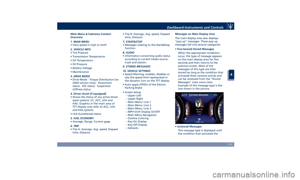
The main display area also displays
"pop up" messages. These pop up
messages fall into several categories:
• Five-Second Stored Messages
When the appropriate conditions
occur, this type of message appears
on the main display area for five
seconds and then returns to the
previous screen. Most of the
messages of this type are then
stored (as long as the condition that
activated them remains active) and
can be reviewed from the "Stored
Messages" main menu item.
Example of this message type is the
one shown in the picture.
• Unstored Messages
This message type is displayed until
the condition that activated theDashboard Instruments and Controls
4
153