change time MASERATI GHIBLI 2019 Owner's Manual
[x] Cancel search | Manufacturer: MASERATI, Model Year: 2019, Model line: GHIBLI, Model: MASERATI GHIBLI 2019Pages: 384, PDF Size: 13.33 MB
Page 246 of 384
whenever the brake pads and/or brake
discs are replaced.
Brake Overheating Driving on mountain roads with steep
slopes or a sports use of the vehicle
could overheat the brake system
components. In these conditions, the
parking brake must not be used since
the push of the power actuator might
not be sufficient to ensure vehicle
braking, especially on a slope.
Drive normally without braking to
allow the brakes to cool down a few
minutes before stopping. The
automatic or manual activation of the
parking brake will ensure vehicle
braking.
Brake overheating could also cause
“squeals” and “vibration”. Use of the Engine Breaking-In Today's most modern production
methods are designed to provide
extremely precise construction and
assembly of components. However,
moving parts do undergo a settling
process, basically in the first hours of
vehicle operation.
Do not drive keeping at a constant
high speed rate for a prolonged time.
While cruising, brief full-throttle
acceleration within the limits of local
traffic laws contributes to a good
break-in. Wide-open throttle
acceleration in low gear can be
detrimental and should be avoided.
The engine oil installed in the engine
at the factory is a high-quality energy
conserving type lubricant. Oil changes
should be consistent with anticipated
climate conditions under which vehicle
operations will occur. For the
recommended viscosity and quality
grades, see “Refillings” in section
“Features and Specifications”.
A new engine may consume some oil
during its first few thousand
miles/kilometers of operation. This
should be considered as a normal part of the break-in and not interpreted as
an indication of malfunction.
Specific Requirements
Avoid exceeding 5000 rpm for the first
620 mi trip (1000 km).
After starting the vehicle, do not
exceed 4000 rpm until the engine has
warmed up sufficiently (coolant
temperature: 149-158°F /65 70°).
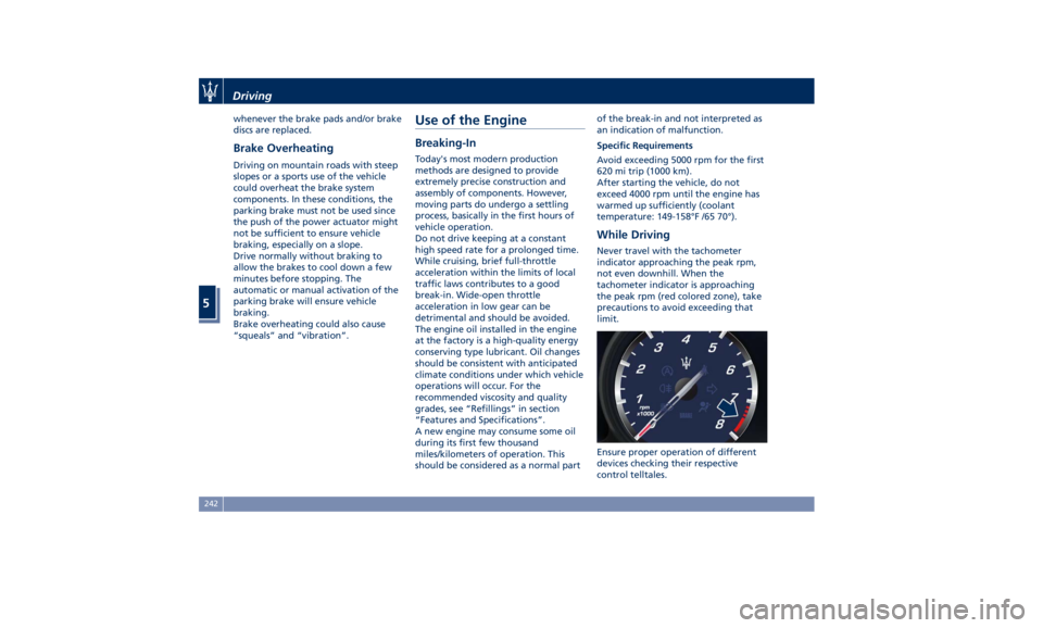
While Driving Never travel with the tachometer
indicator approaching the peak rpm,
not even downhill. When the
tachometer indicator is approaching
the peak rpm (red colored zone), take
precautions to avoid exceeding that
limit.
Ensure proper operation of different
devices checking their respective
control telltales.Driving
5
242
Page 249 of 384
Shared by All Configurations
Multifunction switch:
• Press up (indication RES
+): increase speed, set
current speed or resume
previously set speed
when system is in
“cancelled” status;
• Pushed (indication
CANC): deletes the set
speed;
• Press down (indication
SET -): set speed/decrease
speed.
NOTE:
• The figures only show the Standard
Configuration.
• In order to ensure proper operation,
the CC system has been designed to
shut down if multiple systems are
operated at the same time (example:
ACC and FCW). When conditions so
allow, the CC system can be
reactivated by pushing the CC
“ON/OFF” button or the ACC Gap
button (in the Optional
Configuration) and resetting the
desired vehicle set speed. Displayed Information CC conditions are displayed on the
instrument cluster after selecting
“Driver Assist” menu (see paragraph
“TFT Display: Menus and Settings"
under “Instrument Cluster” in section
“Dashboard Instruments and
Controls”).
Displayed information depends on
system status: ready, disabled,
cancelled or set.
Apart from the pop-up messages at
the centre of the display, CC system
status is represented by icons at the
top left. These icons remain displayed
even when you exit the "Driver Assist"
screen.
The CC screen can be displayed any
time the driver changes system status
or settings. After 5 seconds of CC
inactivity, the display goes back to last
screen.
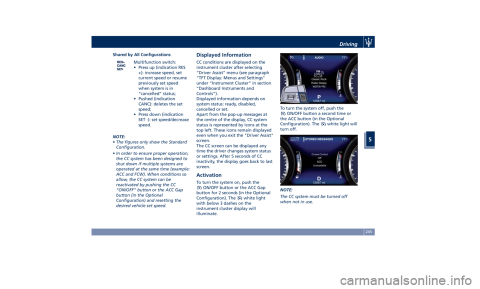
Activation To turn the system on, push the
ON/OFF button or the ACC Gap
button for 2 seconds (in the Optional
Configuration). The
white light
with below 3 dashes on the
instrument cluster display will
illuminate. To turn the system off, push the
ON/OFF button a second time or
the ACC button (in the Optional
Configuration). The
white light will
turn off.
NOTE:
The CC system must be turned off
when not in use.Driving
5
245
Page 252 of 384

safety system and is not designed to
prevent accidents.
The ACC allows driver to keep Cruise
Control active in limited or moderate
traffic conditions with no need to
constantly restore the Cruise Control.
The ACC uses a radar sensor, located
on the front grille behind the trident,
and the forward-facing camera behind
the internal rear-view mirror to detect
the presence of a vehicle ahead at a
close distance and moving in the same
direction.
This vehicle, in this chapter, will be
indicated as "target vehicle" or
"vehicle ahead".
NOTE:
• If the sensor detects no vehicle
ahead, the ACC system will maintain
set steady speed.
• If the ACC sensor detects a vehicle ahead, the ACC system automatically
kicks in by slightly accelerating or
braking (to avoid exceeding the
initially set speed) so that the vehicle
keeps present distance, trying to
adapt to the speed of the detected
vehicle ahead.
WARNING!
• The Adaptive Cruise Control (ACC) is
designed to increase vehicle driving
comfort. It must not be considered
as a means of replacing the required
attention of the driver. The driver is
always required to drive carefully.
The driver is always required to pay
utmost attention to driving
conditions (road, traffic, weather)
and style (speed, distance from
sensed vehicle ahead, brake use).
Driver has the full responsibility of
the vehicle therefore his attention is
crucial to keeping vehicle control, in
particular when approaching curves
and situations with heavy traffic.
Failure to follow these warnings can
result in a collision and death or
serious personal injury.
• In some driving scenarios, the ACC
could have detection problems. In
such cases, the ACC could kick in late or unexpectedly. The driver must be
careful since his/her intervention
could be necessary.
• It is always the driver’s responsibility
to obey speed limits and to keep
minimum legal distance to the
preceding vehicle.
• ACC system can decelerate only with
limited braking, it cannot execute
emergency braking.
The ACC system:
•
Does not activate/react in the
presence of pedestrians, bicycles,
incoming traffic from the opposite
direction and steady objects such as a
vehicle stuck in a traffic jam.
• Is meant for the use on highways and
well-built roads, not for city traffic or
mountain roads.
• May not have enough time to react
and/or decelerate sufficiently on
vehicles when lane is changed too
quickly or the relative speed is too
high. In such cases the driver has to
react appropriately and without any
acoustic/visual and warning.
• Cannot consider road, traffic and
weather conditions and might prove
limited when visibility is poor.
• Does not always fully recognize
complex driving conditions and thisDriving
5
248
Page 253 of 384
could cause an incorrect assessment
of the required safety distance.
It is recommended to disable the ACC
system in the following instances:
• When driving in the fog, heavy rain,
heavy snow, slush, heavy traffic and
similar complex situations such as
highway construction zones.
• When entering a junction lane or a
slip road to leave the highway; when
driving on narrow, icy, snowy,
slippery roads, or on steep uphill and
downhill roads.
• When circumstances do not allow to
drive safely at constant speed.
Displayed information Adaptive Cruise Control (ACC)
condition, as well as the LKA and HAS
status, is displayed on instrument
cluster after selecting “Driver Assist”
menu (see paragraph “TFT Display:
Menus and Settings" under
“Instrument Cluster” in section
“Dashboard Instruments and
Controls”).
Displayed information depends on
system status: ready, set, temporarily
cancelled or override.
Apart from the image at the center of
the display, CC, ACC, LKA and HAS
systems status is represented by icons at the top left and right. These icons
remain displayed even when exiting
the "Driver Assist" screen.
The vehicle(s) and horizontal bars
represent the ACC status as ready
(white) or with sensed vehicle ahead
(green); the white, grey or yellow lines
represent the LKA and HAS systems.
The ACC screen can be displayed any
time driver changes system status or
settings. After 5 seconds of ACC
inactivity, the display goes back to last
screen.
ACC Controls and Activation
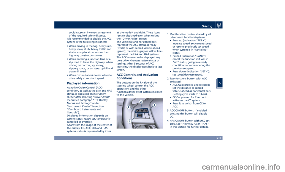
Conditions The buttons on the RH side of the
steering wheel control the ACC
operations and the other
functions/driver assist systems installed
to this vehicle. 1 Multifunction control shared by all
driver assist functions/systems:
• Press up (indication “RES +”):
increase speed, set current speed
or resume previously set speed
when system is in “cancelled”
status.
• Pushed (indication “CANC”):
cancel the function if it was in
“set” status, going in a ready
condition but remembering the
previous set speed.
• Press down (indication “SET -”):
set speed/decrease speed.
2 Two functions button with ACC
activated:
• ACC Gap: pressed and released;
set the distance to sensed
vehicle ahead as horizontal bars
(setting cycle starts to 3 bars).
• CC On: pressed for 2 seconds
activates the CC system.
• Press it to switch from CC to
ACC.
3 ACC ON/OFF button. If enabled,
pressing this button will disable
CC.
4 HAS ON/OFF button with ACC set
only . See "Highway Assist - HAS"
in this section for further details.Driving
5
249
Page 254 of 384
NOTE:
Any change made to tire dimensions
affects performance of Adaptive Cruise
Control and Front Collision Warning
(FCW), if equipped.
The ACC is not activated in the
following conditions:
• When braking.
• When parking brake is activated.
• When automatic transmission is in P
(Park), R (Reverse) or N (Neutral).
• When vehicle speed is out of preset
speed range
• When brakes are overheated.
• When driver door is open.
• When the driver’s seat belt is
unbuckled.
• When the road is particularly steep
(both uphill and downhill) at low
speed.
• When drive mode
(ESC OFF) is
selected.
• When the door is opened at low
speed.
• When there has been an ESC event in
the last 5 seconds, or is still active.
• When there is an object too close in
front of the vehicle.
It is possible that more than one
system is active at the same time such as ACC and ABSA just to mention
some.
While activation of ACC and CC at the
same time is impossible.
Speed Range of Use Speed mph (km/h)
Minimum 0 (0)
Engaged/activated 18 (30)
Maximum 130 (210)
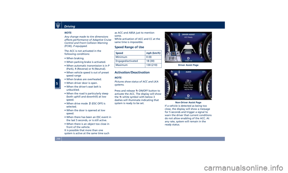
Activation/Deactivation NOTE:
Pictures show status of ACC and LKA
systems.
Press and release
ON/OFF button to
activate the ACC. The display will show
the
white symbol with below 3
dashes will illuminate indicating that
system is ready to be set.
If a vehicle is detected as being too
close, the display will show a message
for 5 seconds and trigger a signal to
warn the driver that current conditions
do not allow enabling of the ACC. At
any rate, system will remain in the
ready status. Driver Assist Page
Non-Driver Assist PageDriving
5
250
Page 257 of 384
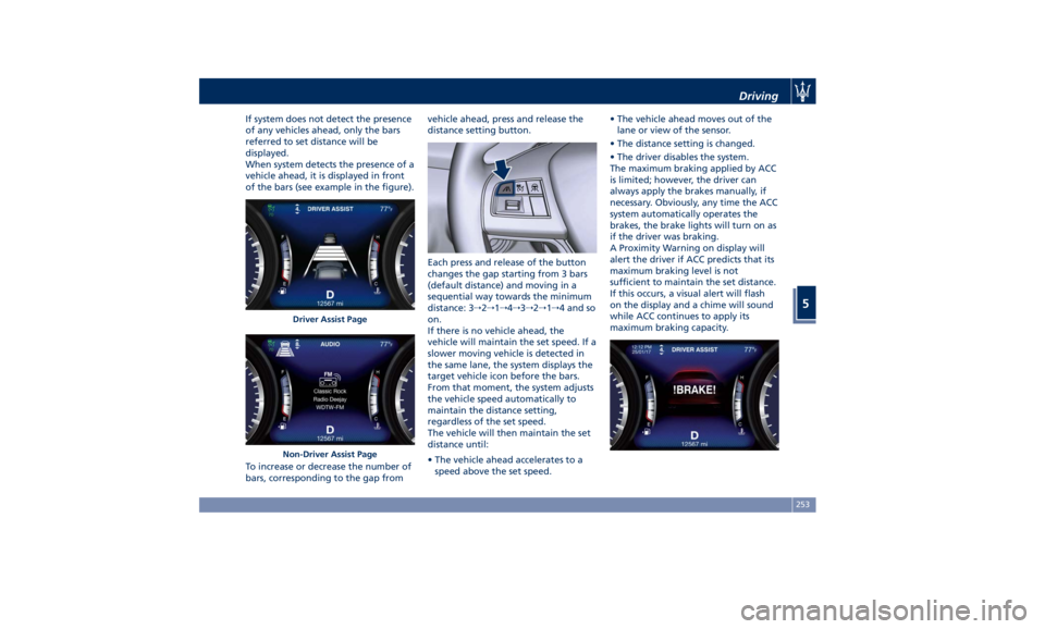
If system does not detect the presence
of any vehicles ahead, only the bars
referred to set distance will be
displayed.
When system detects the presence of a
vehicle ahead, it is displayed in front
of the bars (see example in the figure).
To increase or decrease the number of
bars, corresponding to the gap from vehicle ahead, press and release the
distance setting button.
Each press and release of the button
changes the gap starting from 3 bars
(default distance) and moving in a
sequential way towards the minimum
distance: 3 → 2 → 1 → 4 → 3 → 2 → 1 → 4 and so
on.
If there is no vehicle ahead, the
vehicle will maintain the set speed. If a
slower moving vehicle is detected in
the same lane, the system displays the
target vehicle icon before the bars.
From that moment, the system adjusts
the vehicle speed automatically to
maintain the distance setting,
regardless of the set speed.
The vehicle will then maintain the set
distance until:
• The vehicle ahead accelerates to a
speed above the set speed. • The vehicle ahead moves out of the
lane or view of the sensor.
• The distance setting is changed.
• The driver disables the system.
The maximum braking applied by ACC
is limited; however, the driver can
always apply the brakes manually, if
necessary. Obviously, any time the ACC
system automatically operates the
brakes, the brake lights will turn on as
if the driver was braking.
A Proximity Warning on display will
alert the driver if ACC predicts that its
maximum braking level is not
sufficient to maintain the set distance.
If this occurs, a visual alert will flash
on the display and a chime will sound
while ACC continues to apply its
maximum braking capacity.Driver Assist Page
Non-Driver Assist Page Driving
5
253
Page 264 of 384
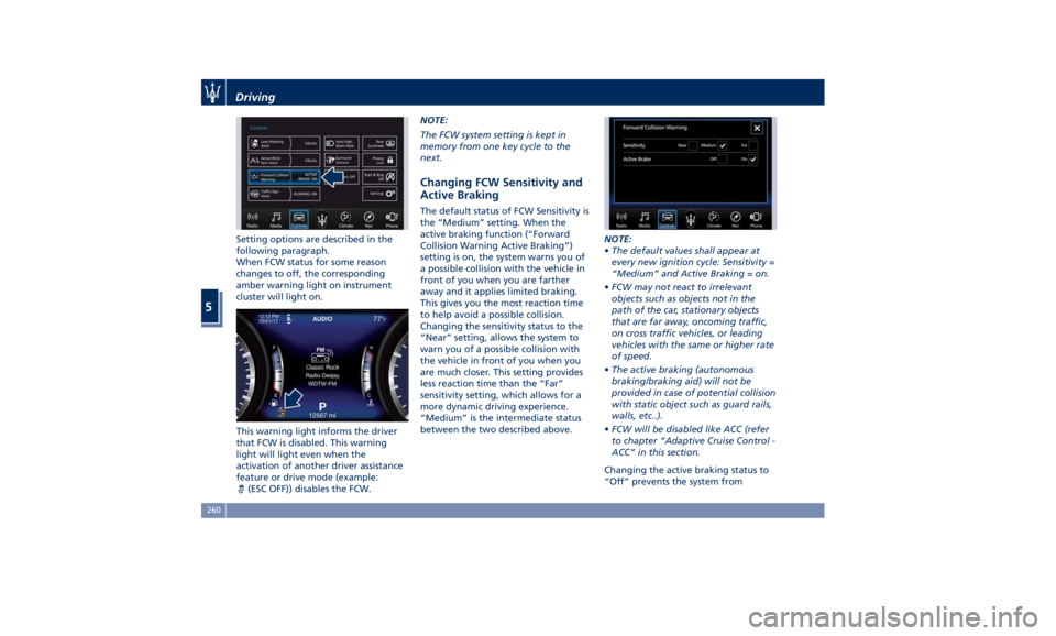
Setting options are described in the
following paragraph.
When FCW status for some reason
changes to off, the corresponding
amber warning light on instrument
cluster will light on.
This warning light informs the driver
that FCW is disabled. This warning
light will light even when the
activation of another driver assistance
feature or drive mode (example:
(ESC OFF)) disables the FCW. NOTE:
The FCW system setting is kept in
memory from one key cycle to the
next.
Changing FCW Sensitivity and
Active Braking The default status of FCW Sensitivity is
the “Medium” setting. When the
active braking function (“Forward
Collision Warning Active Braking”)
setting is on, the system warns you of
a possible collision with the vehicle in
front of you when you are farther
away and it applies limited braking.
This gives you the most reaction time
to help avoid a possible collision.
Changing the sensitivity status to the
“Near” setting, allows the system to
warn you of a possible collision with
the vehicle in front of you when you
are much closer. This setting provides
less reaction time than the “Far”
sensitivity setting, which allows for a
more dynamic driving experience.
“Medium” is the intermediate status
between the two described above. NOTE:
• The default values shall appear at
every new ignition cycle: Sensitivity =
“Medium” and Active Braking = on.
• FCW may not react to irrelevant
objects such as objects not in the
path of the car, stationary objects
that are far away, oncoming traffic,
on cross traffic vehicles, or leading
vehicles with the same or higher rate
of speed.
• The active braking (autonomous
braking/braking aid) will not be
provided in case of potential collision
with static object such as guard rails,
walls, etc..).
• FCW will be disabled like ACC (refer
to chapter “Adaptive Cruise Control -
ACC” in this section.
Changing the active braking status to
“Off” prevents the system fromDriving
5
260
Page 266 of 384
NOTE:
In case of wet road or raining
conditions the function could be
disabled by the system in order to
minimize the risks.
Speed Range of Use Speed mph (km/h)
Minimum 37 (60)
Engaged/activated 37 (60)
Maximum 112 (180)
Customized Settings LKA is configurable by the driver in
order to maximize its efficiency based
on the driver driving style and the
expectation of the system, reducing at
the same time the possible
invasiveness.
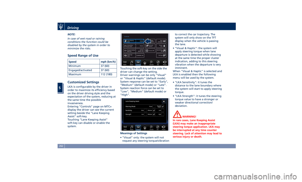
Entering "Controls" page on MTC+
display the driver can see the current
setting beside the "Lane Keeping
Assist" soft-key.
Touching “Lane Keeping Assist”
soft-key can disable or enable the
system. Touching the soft-key on the side the
driver can change the setting.
Driver warnings can be only "Visual"
or "Visual & Haptic" (default mode).
System response can be set to "Early",
"Medium" (default mode) or "Late".
System reaction force can be set to
"Low", "Medium" (default mode) or
"High".
Meanings of Settings
• "Visual" only: the system will not
request any steering torque/vibration to correct the car trajectory. The
system will only show on the TFT
display when the vehicle is passing
the lane.
• "Visual & Haptic": the system will
apply steering torque when lane
departure is detected while showing
at the same time the proper cluster
indication, adding to this steering
vibration when the departure is very
imminent.
When "Visual & Haptic" is selected and
LKA is enabled then the following
menu will be used by the system.
• "LKA Sensitivity": it tunes the
distance to the lane boundary where
the system will start to apply steering
torque.
• "LKA Strength": it tunes the steering
torque value to have a stronger or
weaker directional correction/
deviation.
WARNING!
In rare cases, Lane Keeping Assist
(LKA) may make an inappropriate
steering torque application. LKA may
be interrupted at any time counter
steering. Lack of attention may lead to
serious injury or death.Driving
5
262
Page 267 of 384
System Availability The ADAS systems (LKA, CC, ACC, FCW
and HAS) help the driver while
driving. These systems can be set and
monitored simultaneously on the
display, after opening “Driver Assist”
menu (see paragraph “TFT Display:
Menus and Settings” under
“Instrument Cluster” in section
“Dashboard Instruments and
Controls”).
LKA is designed for an attentive
driver; therefore the system is
available only when his/her hands are
on the steering wheel or with hands
off for only a limited amount of time.
When the system is enabled it will
trigger cluster warning in case at least
one hand is not detected on the
steering wheel.
The torque application as well as the
vibration are suppressed/inhibited in
case of: high driver torque in the
steering wheel, high lateral
acceleration, hands not on the
steering wheel detected for more than
a certain time.
High dynamic driving behaviors,
driving on the lane boundary, or
driving off course will prevent the
function from working. FCW braking
and stability system interventions (ESC, ABS) will also prevent the system from
operating. Changing lanes results in
system inhibition for a certain time. In
addition, the driver must respect some
road characteristics such as
minimum-maximum width, lanes
clearly defined by two lane
boundaries and, only in limited cases
and for a limited time, at least one
lane boundary.
NOTE:
• In case of wet road or raining
conditions the function could be
disabled by the system in order to
minimize the risks.
• With lane boundaries it is mainly
referred to painted lines,
nevertheless the system in good
conditions might properly recognize
as valid lane boundaries also other
types (for example road edges,
curbs, etc..).
Being this function used to prevent
unintentional lane change/lane drift,
it will be temporary suppressed/
inhibited by a turn indicator
activation, therefore, graphic warning,
steering torque application and
vibration will be terminated. In this
condition in case of a vehicle detected
by the Blind Spot Assist (BSA) system in the covered area on the proper
side, there can be the transition from
LKA to Active Blind Spot Assist (ABSA)
(if this latter is on and properly
configured).
Function Description and
Operating Mode The intent of the function is to
prevent the lane departure by
warning the driver through indication
on the cluster and, if set, applying
steering torque and vibration.
Whenever the system is enabled there
will be graphic on the dedicated
screen in the driver assist page and for
the others it will be available in the
left top corner of the cluster screen.
The graphic which intent is to
represent at the glance the system
knowledge of the lane in front of the
car, the system suppression status and
warning.
For this reason, a simple colour code
has been adopted for each line (of the
two presented):
• Both grey lines means system is
enabled, not able to operate
(suppression condition present or
lane detection system not able to
properly estimate the lane);Driving
5
263
Page 269 of 384

rain, snow, wet roads, fog, direct sun
on the camera, etc.).
NOTE:
• The presence of the hands on the
steering wheel is detected by a logic
combination of a capacitive sensor
installed in the steering wheel and
the measured applied torque at the
steering column. This leads to a
more robust hands detection when
hands are actually on the steering
wheel (at least one).
• The sensors are not able to detect
the presence of the hands on the
steering wheel areas covered in
wood, plastic bezels or carbon
inserts (where present).
Sharp turns, slopes and change in
slopes, poor lane boundaries, as well
as construction areas and all the
scenario described in this paragraph
may challenge the system, therefore
be always ready to prevent any
unexpected behaviour of the car.
Damaged front bumper, windshield
replaced without proper technical
intervention may also lead to system
malfunction or system unavailability.
Other conditions such as fault, but not
explicitly indicated here may also prevent/interrupt the system
intervention.
WARNING!
If the driver fails to adapt his/her
driving style, Lane Keeping Assist
(LKA) can neither reduce the risk of an
accident nor override the laws of
physics. It cannot take into account
road, weather or traffic conditions.
Active LKA is only an aid. Driver is
always responsible for the distance to
the vehicle in front, for vehicle speed,
for braking in good time and for
staying in lane.
System in Fault When the LKA cannot properly
operate due to a fault of its
components or because the
windshield in front of the forward
facing camera is dirty, the amber light
and/or the corresponding message will
be displayed. If message suggestion does not allow
fixing the fault, do not use the system
and have the vehicle inspected at an
Authorized Maserati Dealer .
Radar Device - Regulatory
Information The “Regulatory Information” for all
the radio frequency and radar devices
can be consulted by accessing the
“Services” section on the website
www.maserati.com.Driving
5
265