automatic transmission MASERATI GHIBLI 2019 Owners Manual
[x] Cancel search | Manufacturer: MASERATI, Model Year: 2019, Model line: GHIBLI, Model: MASERATI GHIBLI 2019Pages: 384, PDF Size: 13.33 MB
Page 41 of 384
How to use Remote Start All of the following conditions must
be met before the engine will remote
start:
• System not disabled from previous
remote start event.
• Vehicle theft alarm not active.
• Doors closed.
• Hood closed.
• Trunk lid closed.
• Hazard lights switched off.
• Brake pedal not pressed.
• Battery at an acceptable charge
level.
• The shift lever is in P (Park) position.
• The vehicle transmission is in
automatic mode.
• The remote start has not been
activated yet two consecutive times.
If EPB (Electric Parking Brake) is not
selected, at key-off in some conditions
the remote start system may not allow
engine to start. We suggest to set
“Auto Apply On” function through
the switch on the right-side of the
steering wheel (refer to “Instrument
Cluster” in section “Dashboard
Instrument and Controls”). WARNING!
• Do not start or run an engine in a
closed garage or confined area.
Exhaust gas contains Carbon
Monoxide (CO) which is odorless
and colorless
• Keep key fobs RKE transmitter away
from children. Operation of the
Remote Start System, windows,
door locks or other controls could
cause serious injury or death.
Engine Remote Start Abort
Message on Instrument Cluster The following messages will display on
the instrument cluster if the vehicle
fails to remote start or exits remote
start prematurely:
• “Remote Start Canceled Door
Open”.
• “Remote Start Canceled Trunk
Open”.
• “Remote Start Canceled Fuel Low”.
• “Remote Start Canceled Time
Expired”.
• “Remote Start Disabled Start Vehicle
to Reset”. The message on the instrument cluster
stays active as long as the ignition
switch is in RUN position.
To enter Remote Start Mode Press and release the button on the
key fob RKE transmitter twice within
five seconds. The vehicle doors will
lock, position lights will flash and the
horn will ring twice (if this function is
set using the MTC+ System, refer to
“MTC+ Settings” in section
“Dashboard Instruments and
Controls”). Then, the engine will start
and the vehicle will remain in the
“Remote Start” mode for a 15-minute
cycle.
WARNING!
California Proposition 65
Operating, servicing and maintaining
a passenger vehicle or off-road vehicle
can expose you to chemicals including
such as, engine exhaust, carbon
monoxide, phthalates and lead, that
which are known to the State of
California to cause cancer and birth
defects or other reproductive harm. To
minimize exposure, avoid breathing
exhaust, do not idle the engine except
as necessary, service your vehicle in a
(Continued)Before Starting
2
37
Page 44 of 384
If Power Trunk Lid/ Hands Free (if
equipped) has been left open, it will
stay open when you press lock button
, and the locking feature will only
occur after the closing of the power
trunk lid.
The doors can also be locked and
unlocked with the “Passive Entry”
system. For further information, see
“Passive Entry System” in this section.
If you press the power door lock switch
while the ignition switch is in the ACC
or RUN position, and any front door is
open, the power locks will not
operate. This prevents you from
accidentally locking the key fob RKE
transmitter in the vehicle.
Cycling the ignition to the OFF
position or closing the door will allow
the locks of the doors and fuel filler
door to operate. If a door is open with
the key fob RKE transmitter inside the
cabin and the ignition is in the ACC or
RUN position, a beep will draw the
driver’s attention.
Automatic Locking Doors
The auto door lock feature default
condition is disabled. When enabled,
the door locks will lock automatically
when the vehicle's speed exceeds
15 mph (24 km/h). The auto door lock
feature can be enabled or disabled by an Authorized Maserati Dealer only
which can also service the vehicle.
Automatic Door Unlock on Exit
The doors will unlock automatically on
vehicles with power door locks if:
• The automatic unlock doors on exit
feature is enabled.
• The transmission is in gear and the
vehicle speed is 0 (mph - km/h).
• The transmission is in N (Neutral) or P
(Park).
• The driver door is open.
• The doors were not previously
unlocked.
• The vehicle speed is 0 (mph - km/h).
Set Automatic Door Unlock on Exit
To change the current setting, see
“MTC+ Settings” in section
“Dashboard Instruments and
Controls”.
NOTE:
Use the automatic door unlock on exit
feature in accordance with local
regulations. Child-Protection Door Lock
System — Rear Doors To provide a safer environment for
small children sitting in the rear seats,
the rear doors are equipped with a
child-protection door lock system.
Engage or Disengage the
Child-Protection Door Lock
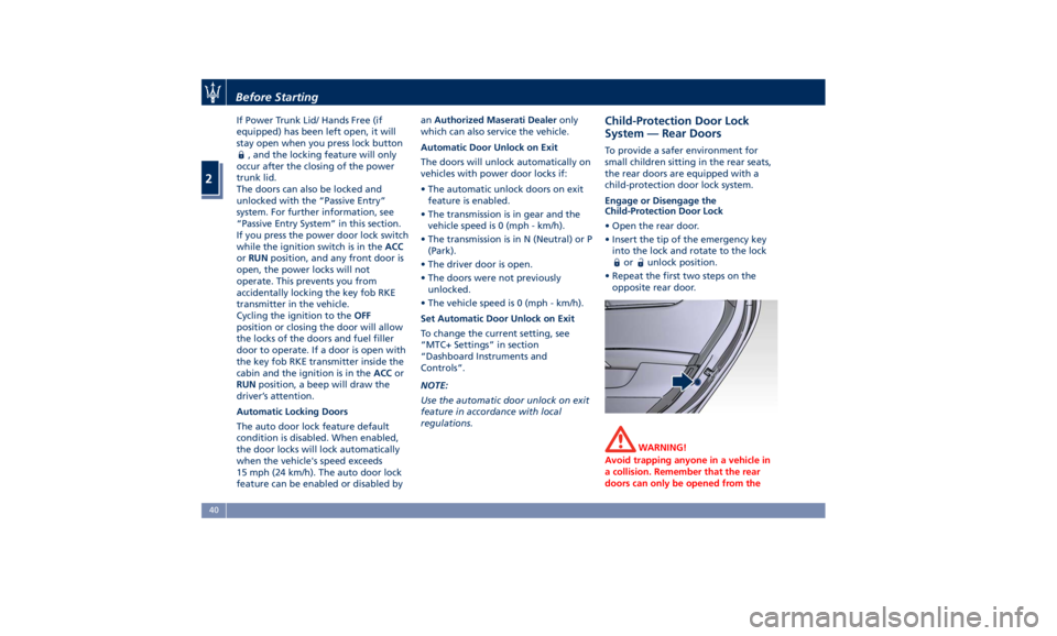
• Open the rear door.
• Insert the tip of the emergency key
into the lock and rotate to the lock
or unlock position.
• Repeat the first two steps on the
opposite rear door.
WARNING!
Avoid trapping anyone in a vehicle in
a collision. Remember that the rear
doors can only be opened from theBefore Starting
2
40
Page 52 of 384
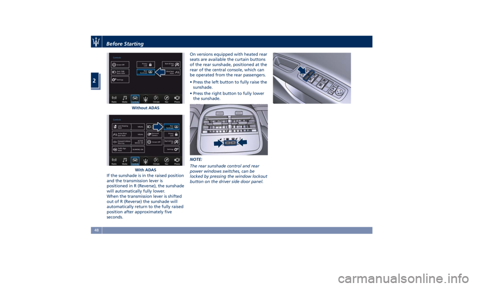
If the sunshade is in the raised position
and the transmission lever is
positioned in R (Reverse), the sunshade
will automatically fully lower.
When the transmission lever is shifted
out of R (Reverse) the sunshade will
automatically return to the fully raised
position after approximately five
seconds. On versions equipped with heated rear
seats are available the curtain buttons
of the rear sunshade, positioned at the
rear of the central console, which can
be operated from the rear passengers.
• Press the left button to fully raise the
sunshade.
• Press the right button to fully lower
the sunshade.
NOTE:
The rear sunshade control and rear
power windows switches, can be
locked by pressing the window lockout
button on the driver side door panel.Without ADAS
With ADASBefore Starting
2
48
Page 59 of 384
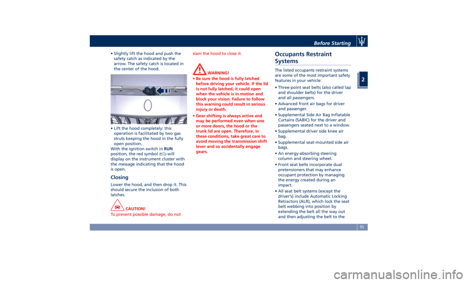
• Slightly lift the hood and push the
safety catch as indicated by the
arrow. The safety catch is located in
the center of the hood.
• Lift the hood completely: this
operation is facilitated by two gas
struts keeping the hood in the fully
open position.
With the ignition switch in RUN
position, the red symbol
will
display on the instrument cluster with
the message indicating that the hood
is open.
Closing Lower the hood, and then drop it. This
should secure the inclusion of both
latches.
CAUTION!
To prevent possible damage, do not slam the hood to close it.
WARNING!
• Be sure the hood is fully latched
before driving your vehicle. If the lid
is not fully latched, it could open
when the vehicle is in motion and
block your vision. Failure to follow
this warning could result in serious
injury or death.
• Gear shifting is always active and
may be performed even when one
or more doors, the hood or the
trunk lid are open. Therefore, in
these conditions, take great care to
avoid moving the transmission shift
lever and so accidentally engage
gears.Occupants Restraint
Systems The listed occupants restraint systems
are some of the most important safety
features in your vehicle:
• Three-point seat belts (also called lap
and shoulder belts) for the driver
and all passengers.
• Advanced front air bags for driver
and passenger.
• Supplemental Side Air Bag Inflatable
Curtains (SABIC) for the driver and
passengers seated next to a window.
• Supplemental driver side knee air
bag.
• Supplemental seat-mounted side air
bags.
• An energy-absorbing steering
column and steering wheel.
• Front seat belts incorporate dual
pretensioners that may enhance
occupant protection by managing
the energy created during an
impact.
• All seat belt systems (except the
driver’s) include Automatic Locking
Retractors (ALR), which lock the seat
belt webbing into position by
extending the belt all the way out
and then adjusting the belt to theBefore Starting
2
55
Page 84 of 384
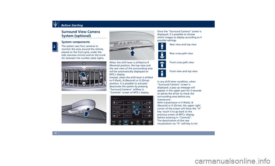
Surround View Camera
System (optional) System components The system uses four cameras to
monitor the area around the vehicle,
placed on the front grid, under the
side rearview mirrors and on the trunk
lid, between the number plate lights.
When the shift lever is shifted to R
(Reverse) position, the top view and
the rear view of the surrounding area
will be automatically displayed on
MTC+ display.
Instead, when the shift lever is shifted
to P (Park), N (Neutral) or D (Drive)
position, it is possible to activate/
deactivate the system by pressing
“Surround Camera” softkey in
“Controls” screen of MTC+ display. Once the “Surround Camera” screen is
displayed, it is possible to choose
which images to display according to 4
possible settings.
Rear view and top view
Rear cross path view
Front cross path view
Front view and top view
In any shift lever condition, when
“Surround Camera” screen is
displayed, a pop-up message will
appear in the upper part for 5 seconds
to advise the driver to check the
surrounding area before any
manoeuvre.
With transmission in P (Park), N
(Neutral) or D (Drive), the upper right
corner of the screen will show the “X”
key: touch it to go back to the
previous screen of MTC+ display,
before entering in “Controls”.
The deactivation of the rear
visualization via “X” soft-key is notBefore Starting
2
80
Page 97 of 384
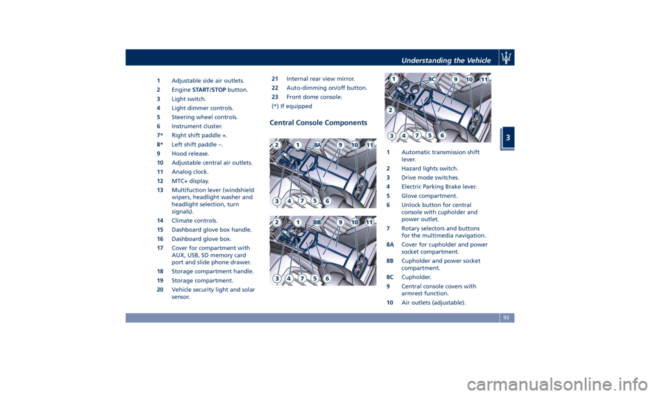
1 Adjustable side air outlets.
2 Engine START/STOP button.
3 Light switch.
4 Light dimmer controls.
5 Steering wheel controls.
6 Instrument cluster.
7* Right shift paddle +.
8* Left shift paddle –.
9 Hood release.
10 Adjustable central air outlets.
11 Analog clock.
12 MTC+ display.
13 Multifuction lever (windshield
wipers, headlight washer and
headlight selection, turn
signals).
14 Climate controls.
15 Dashboard glove box handle.
16 Dashboard glove box.
17 Cover for compartment with
AUX, USB, SD memory card
port and slide phone drawer.
18 Storage compartment handle.
19 Storage compartment.
20 Vehicle security light and solar
sensor. 21 Internal rear view mirror.
22 Auto-dimming on/off button.
23 Front dome console.
(*) If equipped
Central Console Components 1 Automatic transmission shift
lever.
2 Hazard lights switch.
3 Drive mode switches.
4 Electric Parking Brake lever.
5 Glove compartment.
6 Unlock button for central
console with cupholder and
power outlet.
7 Rotary selectors and buttons
for the multimedia navigation.
8A Cover for cupholder and power
socket compartment.
8B Cupholder and power socket
compartment.
8C Cupholder.
9 Central console covers with
armrest function.
10 Air outlets (adjustable).Understanding the Vehicle
3
93
Page 124 of 384
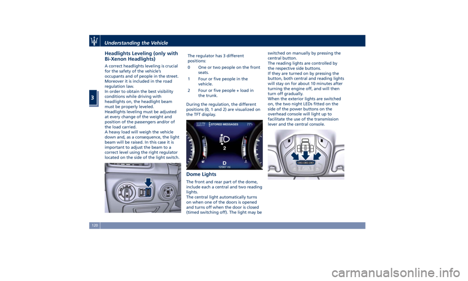
Headlights Leveling (only with
Bi-Xenon Headlights) A correct headlights leveling is crucial
for the safety of the vehicle’s
occupants and of people in the street.
Moreover it is included in the road
regulation law.
In order to obtain the best visibility
conditions while driving with
headlights on, the headlight beam
must be properly leveled.
Headlights leveling must be adjusted
at every change of the weight and
position of the passengers and/or of
the load carried.
A heavy load will weigh the vehicle
down and, as a consequence, the light
beam will be raised. In this case it is
important to adjust the beam to a
correct level using the right regulator
located on the side of the light switch. The regulator has 3 different
positions:
0 One or two people on the front
seats.
1 Four or five people in the
vehicle.
2 Four or five people + load in
the trunk.
During the regulation, the different
positions (0, 1 and 2) are visualized on
the TFT display.
Dome Lights The front and rear part of the dome,
include each a central and two reading
lights.
The central light automatically turns
on when one of the doors is opened
and turns off when the door is closed
(timed switching off). The light may be switched on manually by pressing the
central button.
The reading lights are controlled by
the respective side buttons.
If they are turned on by pressing the
button, both central and reading lights
will stay on for about 10 minutes after
turning the engine off, and will then
turn off gradually.
When the exterior lights are switched
on, the two night LEDs fitted on the
side of the power buttons on the
overhead console will light up to
facilitate the use of the transmission
lever and the central console.Understanding the Vehicle
3
120
Page 128 of 384
arms. It will not operate under the
following conditions:
• Low Temperature Wipe Inhibit : the
rain sensing feature will not operate
when the ignition is in RUN position,
the vehicle is stationary and the
outside temperature is below 32°F
(0°C). To resume, set the automatic
feature on the multifunction lever,
start the engine and drive or wait
until the outside temperature rises
above freezing.
• Wipe Inhibit with Transmission in
Neutral Position : the rain sensing
feature will not operate when the
ignition is placed in the RUN
position, the transmission shift lever
is in the N (Neutral) position and the
vehicle speed is less than 5 mph
(8 km/h). To resume, set the
multifunction lever to the automatic
function or move the shift lever out
of N (Neutral).
Headlights On with Windshield
Wipers When activating this function, the
headlights will light up approximately
10 seconds after the wipers acting on
the windshield are turned on if the
light switch is placed in “AUTO”
position. In addition, the headlights switch off when the wipers are turned
off (position “OFF”) if they were
previously turned by using this
function. Powering on Headlights with
wipers can be activated and
deactivated with the MTC+ System, see
“MTC+ Settings” in section
“Dashboard Instruments and Controls”
for further information.
Wiper Blade Maintenance When the wiper arms acting on the
windshield are in the rest position it is
not possible to check or replace the
blades (Service position) as they are
folded under the hood. To service the
blades (see paragraph “Wiper
Maintenance and Blades
Replacement” in chapter
“Maintenance Procedures” of section
“Maintenance and Care”) it is
necessary to shift the multifunction
lever to “OFF” and the ignition switch
to OFF position.
Shift the control lever within 15
seconds to the “MIST” position
(forward rotation of the end of the
multifunction control lever) and
release. The blades are brought in a
position enabling to open the wiper
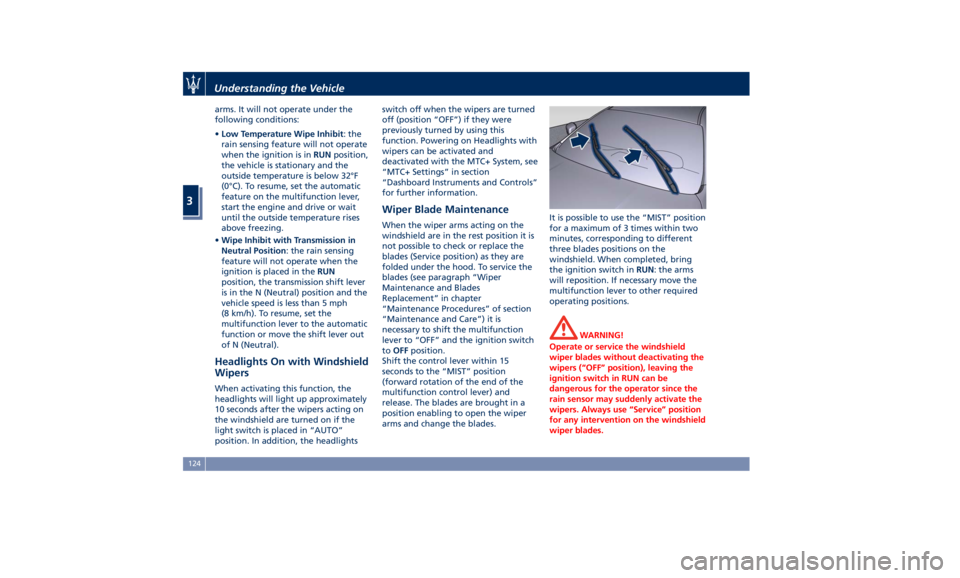
arms and change the blades. It is possible to use the “MIST” position
for a maximum of 3 times within two
minutes, corresponding to different
three blades positions on the
windshield. When completed, bring
the ignition switch in RUN : the arms
will reposition. If necessary move the
multifunction lever to other required
operating positions.
WARNING!
Operate or service the windshield
wiper blades without deactivating the
wipers (“OFF” position), leaving the
ignition switch in RUN can be
dangerous for the operator since the
rain sensor may suddenly activate the
wipers. Always use “Service” position
for any intervention on the windshield
wiper blades.Understanding the Vehicle
3
124
Page 151 of 384
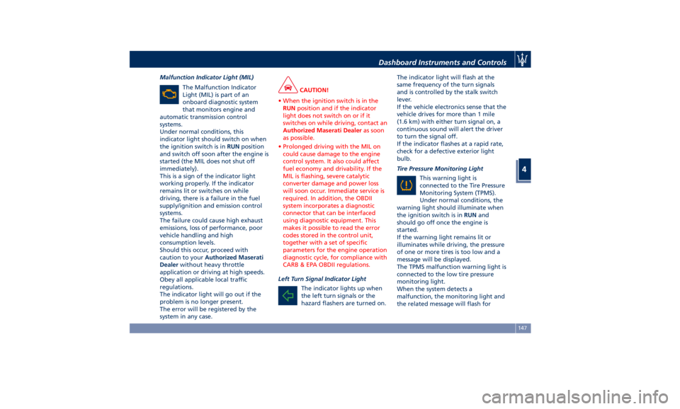
Malfunction Indicator Light (MIL)
The Malfunction Indicator
Light (MIL) is part of an
onboard diagnostic system
that monitors engine and
automatic transmission control
systems.
Under normal conditions, this
indicator light should switch on when
the ignition switch is in RUN position
and switch off soon after the engine is
started (the MIL does not shut off
immediately).
This is a sign of the indicator light
working properly. If the indicator
remains lit or switches on while
driving, there is a failure in the fuel
supply/ignition and emission control
systems.
The failure could cause high exhaust
emissions, loss of performance, poor
vehicle handling and high
consumption levels.
Should this occur, proceed with
caution to your Authorized Maserati
Dealer without heavy throttle
application or driving at high speeds.
Obey all applicable local traffic
regulations.
The indicator light will go out if the
problem is no longer present.
The error will be registered by the
system in any case. CAUTION!
• When the ignition switch is in the
RUN position and if the indicator
light does not switch on or if it
switches on while driving, contact an
Authorized Maserati Dealer as soon
as possible.
• Prolonged driving with the MIL on
could cause damage to the engine
control system. It also could affect
fuel economy and drivability. If the
MIL is flashing, severe catalytic
converter damage and power loss
will soon occur. Immediate service is
required. In addition, the OBDII
system incorporates a diagnostic
connector that can be interfaced
using diagnostic equipment. This
makes it possible to read the error
codes stored in the control unit,
together with a set of specific
parameters for the engine operation
diagnostic cycle, for compliance with
CARB & EPA OBDII regulations.
Left Turn Signal Indicator Light
The
indicator lights
up when
the left turn signals or the
hazard flashers are turned on. The indicator light will flash at the
same frequency of the turn signals
and is controlled by the stalk switch
lever.
If the vehicle electronics sense that the
vehicle drives for more than 1 mile
(1.6 km) with either turn signal on, a
continuous sound will alert the driver
to turn the signal off.
If the indicator flashes at a rapid rate,
check for a defective exterior light
bulb.
Tire Pressure Monitoring Light
This warning light is
connected to the Tire Pressure
Monitoring System (TPMS).
Under normal conditions, the
warning light should illuminate when
the ignition switch is in RUN and
should go off once the engine is
started.
If the warning light remains lit or
illuminates while driving, the pressure
of one or more tires is too low and a
message will be displayed.
The TPMS malfunction warning light is
connected to the low tire pressure
monitoring light.
When the system detects a
malfunction, the monitoring light and
the related message will flash forDashboard Instruments and Controls
4
147
Page 159 of 384
lines are present and turn-by-turn
navigation is on, main menu area will
automatically show navigation
information. For further details, please
refer to MTC+ guide.
2. VEHICLE INFO
Press and release the switch in the
or arrow directions until this
menu item is displayed.
Press and release the switch (
)to
access the submenus.
Press and release the switch in the
or arrow directions to scroll
through the following information
displays pressing and releasing the
switch (
) to display the selected
information.
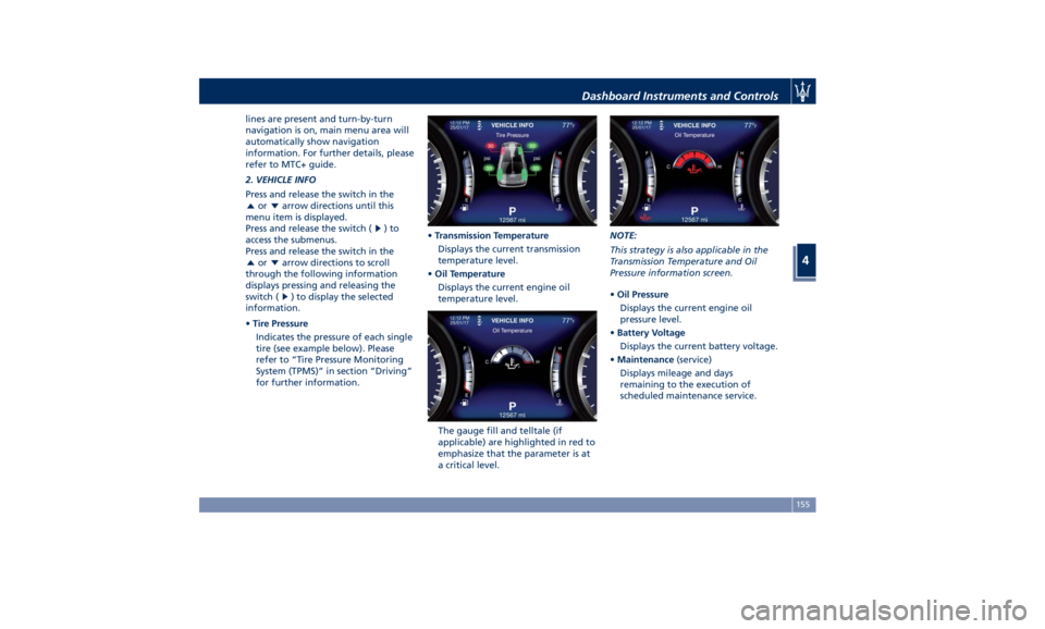
• Tire Pressure
Indicates the pressure of each single
tire (see example below). Please
refer to “Tire Pressure Monitoring
System (TPMS)” in section “Driving”
for further information. • Transmission Temperature
Displays the current transmission
temperature level.
• Oil Temperature
Displays the current engine oil
temperature level.
The gauge fill and telltale (if
applicable) are highlighted in red to
emphasize that the parameter is at
a critical level. NOTE:
This strategy is also applicable in the
Transmission Temperature and Oil
Pressure information screen.
• Oil Pressure
Displays the current engine oil
pressure level.
• Battery Voltage
Displays the current battery voltage.
• Maintenance (service)
Displays mileage and days
remaining to the execution of
scheduled maintenance service.Dashboard Instruments and Controls
4
155