tires MASERATI GHIBLI 2019 Owners Manual
[x] Cancel search | Manufacturer: MASERATI, Model Year: 2019, Model line: GHIBLI, Model: MASERATI GHIBLI 2019Pages: 384, PDF Size: 13.33 MB
Page 88 of 384
system checked by the Authorized
Maserati Dealer .
WARNING!
Certain components of this vehicle
such as air bag modules, seat belt
pretensioners, adaptive steering
columns, and button cell batteries may
contain Perchlorate material. Special
handling may apply for service or
vehicle end of life disposal. See
www.dtsc.ca.gov/hazardouswaste/
perchlorate.
Defroster
Check
operation by
selecting the
defrost mode and place the fan system
on high speed (see “Air Conditioning
Controls” chapter in section
“Dashboard Instruments and
Controls”).
You should be able to feel the air
directed against the windshield and
front side windows. Contact
Authorized Maserati Dealer for service
if your defroster is inoperable.
Floor Mat
Always use floor mats designed to fit
the footwell of your vehicle. Use only
floor mats that leave the pedal area
unobstructed and that are firmly secured so that they cannot slip out of
position and interfere with the pedals
or impair safe operation of your
vehicle.
NOTE:
The Authorized Maserati Dealer can
provide you with any information
about the available Maserati floor
mats included in the “Genuine
Accessories” range.
WARNING!
Pedals that cannot move freely can
cause loss of vehicle control and
increase the risk of serious personal
injury.
• Always make sure that floor mats
are properly attached to the proper
fasteners.
• Never place or install floor mats or
other floor coverings in the vehicle
that cannot be properly secured to
prevent them from moving and
interfering with the pedals.
• Never put floor mats or other floor
coverings on top of already installed
floor mats. Additional floor mats and
other coverings will reduce the size
of the pedal area and interfere with the pedals.
• Check mounting of mats on a regular
basis. Always properly reinstall and
secure floor mats that have been
removed for cleaning.
• Always make sure that objects
cannot fall into the driver footwell
while the vehicle is moving. Objects
can become trapped under the brake
pedal and accelerator pedal causing
a loss of vehicle control.
• Mounting posts must be properly
installed, if not equipped from the
factory. Failure to properly follow
floor mat installation or mounting
can cause interference with the
brake pedal and accelerator pedal
operation causing loss of control of
the vehicle.
Tires
•
Examine tires for excessive tread
wear and uneven wear patterns.
• Check for stones, nails, glass, or other
objects lodged in the tread or
sidewall.
• Inspect the tread for cuts and cracks.
• Inspect sidewalls for cuts, cracks and
bulges.
• Check the wheel nuts for tightness.Before Starting
2
84
Page 89 of 384
• Check the tires (see “Tire Inflation
Pressure” chapter in section
“Features and Specifications”) for
proper cold inflation pressure.
Lights and Indicator Lights
• Have someone observe the
operation of exterior lights while
you operate the controls (see
“Lights” chapter in section
“Understanding the Vehicle”).
• Check turn signal and high beam
indicator lights on the instrument
cluster (see “Instrument Cluster”
chapter in section “Dashboard
Instruments and Controls”).
Door Latches
• Check for positive closing, latching,
and locking of doors and trunk lid
(see “Unlock the Vehicle with Key
fob” chapter in this section).
Fluid Leaks
• Check area under vehicle after
overnight parking for recent fluid
leaks (oil, fuel, etc.).
• If gasoline fumes are detected or
fluid leaks are suspected, contact the
Authorized Maserati Dealer . WARNING!
California Proposition 65
Operating, servicing and maintaining
a passenger vehicle or off-road vehicle
can expose you to chemicals including
such as, engine exhaust, carbon
monoxide, phthalates and lead, that
which are known to the State of
California to cause cancer and birth
defects or other reproductive harm. To
minimize exposure, avoid breathing
exhaust, do not idle the engine except
as necessary, service your vehicle in a
well-ventilated area and wear gloves
or wash your hands frequently when
servicing your vehicle. For more
information go to:
www.P65Warnings.ca.gov/passenger-
vehiclePark Assist (if equipped) The Park Assist (also called
“ParkSense”) system provides visual
and audible indications of the distance
between the rear and/or front bumper
and a detected obstacle when backing
up or moving forward, e.g. during a
parking maneuver.
Besides the use of the sensors
available on the bumpers and of the
rear parking camera, the vehicle may
be equipped with surround view
cameras (optional) to assist the driver
during maneuvers on dead-ends/roads
and on intersections. For more details
on this option, see chapter "Surround
View Camera System (optional)" in
this section.
Refer to “Park Assist System Usage
Precautions” for limitations of this
system and recommendations.
Park Assist system will retain the last
system state (enabled or disabled)
from the last ignition cycle when the
ignition is changed to the RUN
position.
Park Assist system can be active only
when the shift lever is in R (Reverse) or
D (Drive).
If Park Assist is enabled at one of
these shift lever positions, the system
will remain active until the vehicleBefore Starting
2
85
Page 151 of 384
Malfunction Indicator Light (MIL)
The Malfunction Indicator
Light (MIL) is part of an
onboard diagnostic system
that monitors engine and
automatic transmission control
systems.
Under normal conditions, this
indicator light should switch on when
the ignition switch is in RUN position
and switch off soon after the engine is
started (the MIL does not shut off
immediately).
This is a sign of the indicator light
working properly. If the indicator
remains lit or switches on while
driving, there is a failure in the fuel
supply/ignition and emission control
systems.
The failure could cause high exhaust
emissions, loss of performance, poor
vehicle handling and high
consumption levels.
Should this occur, proceed with
caution to your Authorized Maserati
Dealer without heavy throttle
application or driving at high speeds.
Obey all applicable local traffic
regulations.
The indicator light will go out if the
problem is no longer present.
The error will be registered by the
system in any case. CAUTION!
• When the ignition switch is in the
RUN position and if the indicator
light does not switch on or if it
switches on while driving, contact an
Authorized Maserati Dealer as soon
as possible.
• Prolonged driving with the MIL on
could cause damage to the engine
control system. It also could affect
fuel economy and drivability. If the
MIL is flashing, severe catalytic
converter damage and power loss
will soon occur. Immediate service is
required. In addition, the OBDII
system incorporates a diagnostic
connector that can be interfaced
using diagnostic equipment. This
makes it possible to read the error
codes stored in the control unit,
together with a set of specific
parameters for the engine operation
diagnostic cycle, for compliance with
CARB & EPA OBDII regulations.
Left Turn Signal Indicator Light
The
indicator lights
up when
the left turn signals or the
hazard flashers are turned on. The indicator light will flash at the
same frequency of the turn signals
and is controlled by the stalk switch
lever.
If the vehicle electronics sense that the
vehicle drives for more than 1 mile
(1.6 km) with either turn signal on, a
continuous sound will alert the driver
to turn the signal off.
If the indicator flashes at a rapid rate,
check for a defective exterior light
bulb.
Tire Pressure Monitoring Light
This warning light is
connected to the Tire Pressure
Monitoring System (TPMS).
Under normal conditions, the
warning light should illuminate when
the ignition switch is in RUN and
should go off once the engine is
started.
If the warning light remains lit or
illuminates while driving, the pressure
of one or more tires is too low and a
message will be displayed.
The TPMS malfunction warning light is
connected to the low tire pressure
monitoring light.
When the system detects a
malfunction, the monitoring light and
the related message will flash forDashboard Instruments and Controls
4
147
Page 171 of 384
“Automatic Transmission” in section
“Driving”) drive carefully and slow
down as the grip of the tires may be
significantly reduced.
The indicator light flashes for 5
seconds and switches off when the
temperature reaches 43°F (6°C) or
higher.
Electric Parking Brake Failure Warning
Light
This warning light and related
message illuminate when
there is an EPB system failure.
The failure could also
completely or partially block the
vehicle because the parking brake
could remain on even after it has been
automatically or manually disengaged
though its controls.
If it is still possible to use the vehicle
(parking brake not engaged) drive to
the nearest Authorized Maserati
Dealer and remember to performing
each operation/command that the
electric parking brake is not
functioning.
Start&Stop Disable Indicator
This indicator illuminates
when Start&Stop is turned off
through the main menu item
“Start&Stop”, via the controls
located on the right side of the steering wheel, or through the button
on the central console or through the
relevant soft-key of the MTC+. See
chapter “Automatic Start&Stop
System” of section “Driving” for
further information.
Start&Stop Failure Warning Light
This warning light illuminates
when there is a failure in the
Start&Stop system. Switch the
engine on or off using the
normal procedure with the ignition
device START/STOP and have the
vehicle checked at an Authorized
Maserati Dealer .
Scheduled Maintenance (Service)
Indicator
This indicator illuminates and
a message flashes on the
display for approximately 5
seconds after an acoustic
signal to indicate that the next
scheduled maintenance is due or is
already overdue.
Unless reset, the message will
continue to display each time you
cycle the ignition to the RUN position.
To turn off the message temporarily,
press and release the
button on the
steering wheel. To reset the service
indicator system, please visit an
Authorized Maserati Dealer . ADAS Status Indicators (if equipped)
When you are not viewing the
“Drive Assist” page, the
indicators at the top left-hand
side of the display indicate
status of individual ADAS system or
the combination of them (see
examples).
For further details, refer to
“Adaptive Cruise Control -
ACC”, “Lane Keeping Assist -
LKA” and “Highway Assist - HAS” in
section “Driving”.
Forward Collision Warning (FCW) Off
(If equipped)
This warning light informs the
driver that Forward Collision
Warning (FCW) is disabled. If
this light occurs together with
other specific messages, take your
vehicle to an Authorized Maserati
Dealer for service. This warning light
will light even when the activation of
another driver assistance feature or
drive mode (such as “
-ESC OFF”)
disables the FCW.
Forward Collision Warning (FCW)
Fault (If equipped)
This warning light informs
that FCW is in fault state. If
this occurred together with
other specific messages, couldDashboard Instruments and Controls
4
167
Page 211 of 384
5 – Driving Normal Starting of the Engine ............................. 208
Automatic Start&Stop System ............................. 210
Automatic Transmission .................................. 214
All-Wheel Drive (AWD version only) ......................... 223
Drive Mode ........................................... 224
Active Alternator ....................................... 233
Parking Brake ......................................... 233
Parking .............................................. 236
Brake and Stability Control System ......................... 238
Using the Brakes ....................................... 241
Use of the Engine ...................................... 242
Electronic Cruise Control ................................. 244
Adaptive Cruise Control – ACC (optional) ..................... 247
Forward Collision Warning – FCW .......................... 258
Lane Keeping Assist - LKA (optional, with ACC only) ............ 261
Blind Spot Assist (without ACC) ............................ 266
Active Blind Spot Assist - ABSA (optional, with ACC only) ........ 271
Highway Assist – HAS (optional, with ACC only) ................ 274
Traffic Sign Assist – TSA (optional) .......................... 279
Tires - General Information ............................... 281
Tire Pressure Monitoring System (TPMS) ..................... 289
Fuel Requirements ...................................... 294
Refueling ............................................. 296
Driving Conditions ...................................... 298
207
Page 242 of 384
Brake and Stability Control
System The vehicle is equipped with an
Electronic Stability Control System
(ESC), which helps to maintain
directional control in the event of loss
of grip of the tires. The system is able
to detect potentially dangerous
situations for the stability of the
vehicle and automatically sets the
brakes on all four wheels in a
differentiated manner, in order to
provide a torque settlement of the
vehicle.
ESC includes the following subsystems:
• ABS (Anti-lock Braking System);
• EBD (Electronic Brake-force
Distribution);
• TCS (Traction Control System);
• BAS (Brake Assist System);
• BTO (Brake Throttle Override);
• HSA (Hill Start Assist).
WARNING!
• These systems cannot prevent the
natural laws of physics from
affecting the vehicle, nor can they
increase traction, braking or steering
efficiency beyond that afforded by the condition of the vehicle brakes
and tires.
• These systems cannot prevent
collisions, including those resulting
from excessive speed in turns,
following another vehicle too
closely, or hydroplaning.
• The capabilities of a vehicle
equipped with these systems must
never be exploited in a reckless or
dangerous manner that could
jeopardize the driver’s and the
passenger’s safety or the safety of
others.
Electronic Stability Control
(ESC) This system enhances directional
control and stability of the vehicle
under various driving conditions. The
ESC corrects over steering and under
steering of the vehicle by applying the
brake to the appropriate wheel.
Engine power may also be reduced to
assist in counteracting the conditions
of instability and maintain the right
direction. The system is also able to
reduce the engine power.
Through sensors fitted on the vehicle,
the ESC system detects the driver’s
chosen direction comparing it to the
one maintained while running. In case of discrepancy between the required
trajectory and the current one, the ESC
system brakes the appropriate wheel
to counteract over or under steering.
• Oversteer - when the vehicle is
turning more than appropriate for
the steering wheel position.
• Understeer - when the vehicle is
turning less than appropriate for the
steering wheel position.
The ESC system has two available
operating modes:
ESC on
This is the normal ESC operating mode.
At each start-up of the vehicle, the ESC
system is set in this mode and should
be used for most driving conditions.
The ESC should only be turned off for
specific reasons as pointed out in the
following paragraphs.
ESC off
The “ESC off” mode is aimed for a
more spirited driving experience but
also purposeful for driving in deep
snow, sand, or gravel. The current
mode disables the TCS portion of the
ESC and raises the threshold for ESC
activation, allowing higher wheel spin
than normally granted by the ESC
system. The
(ESC OFF) button is
fitted beside the gear shift lever: toDriving
5
238
Page 243 of 384
deactivate the system see “Drive
Mode” in this section.
WARNING!
In SPORT mode the ESC control
thresholds are higher for maximum
performance on dry road surface. To
ensure maximum security of the ESC,
it is recommended not to activate
SPORT mode on surfaces with
medium- and low-grip (e.g., wet,
snow, dirt, etc..) with ESC system
active (
(ESC OFF) button not
pressed).
NOTE:
• When in “ESC off” mode, the TCS
functionality of ESC is deactivated
(except for the limited slip feature
described in the TCS paragraph of
this chapter). All other stability
features of ESC function regularly.
• To improve the vehicle's traction
when driving with snow chains, or
when starting off in deep snow,
sand, or gravel, it may be desirable
to switch to the “ESC off” mode by
pressing the
(ESC OFF) button and
remain in this operational mode no
longer than needed. Once the
situation requiring “ESC off” mode is overcome, turn the ESC on again by
pressing the
(ESC OFF) button.
This may also be performed while in
motion.
Anti-Lock Braking System (ABS)
and Electronic Brake-force
Distribution (EBD) The Anti-Lock Braking System (ABS)
provides increased vehicle stability and
brake performance under most
braking conditions. The system
automatically “pumps” the brakes
during severe braking to prevent
wheel lock-up.
The Electronic Brake-force Distribution
(EBD) prevents the rear wheels from
over-braking and provides greater
control of available braking forces
applied to the rear axle.
WARNING!
The ABS helps prevent the wheels
from locking, but it does not increase
the physical grip limits between the
tires and the road. Therefore, always
keep a safe distance from the vehicle
in front of yours and reduce your
speed when entering a curve. NOTE:
• When
the vehicle's speed is higher
than 7 mph (11 km/h), you may hear
a slight clicking sound as well as
other motor noises. The system is
performing a self-check cycle to
ensure that the ABS is working
properly.
• This self-check occurs each time the
vehicle is started and accelerated
past 7 mph (11 km/h).
ABS is activated during braking under
certain road or stopping conditions.
ABS-inducing conditions can include
ice, snow, gravel, bumps, railroad
tracks, loose debris.
You may also experience the following
when the brake system goes into Anti-
Lock:
• The ABS motor running (it may
continue to run for a short time
after the vehicle stops).
• The clicking sound of solenoid
valves.
• Brake pedal pulsations.
• A slight drop or fall away of the
brake pedal at the end of the stop.
These are all normal characteristics
of ABS functioning.Driving
5
239
Page 285 of 384
speed stays above the unconditioned
speed limit for several seconds the
unconditioned speed limit sign will
stop blinking because the manoeuvre
is evaluated as intentional. If the TSA
is not able to determine any kind of
valid speed limit neither from camera
nor from digital maps the following
image will be shown in sector 2 .
Since TSA also uses the data provided
by the navigation system, it can
update the sector 2 of the display in
the following situations without
detecting traffic signs:
• When the vehicle changes road.
• Highway enter/exit.
• Urban area stored in the digital map
enter/exit.
System Limitations TSA may be impaired or may not
function in the following situations:
• If there is poor visibility, e.g. due to
insufficient illumination of the road,
if there are highly variable shade
conditions or in rain, snow or fog.
• If there is glare, e.g. from oncoming
traffic, direct sunlight or reflections
from other vehicles. • If the windshield in the area of the
camera is dirty, or if the camera is
fogged up, damaged or covered.
• If the traffic signs are hard to detect,
e.g. due to dirt or snow, or because
they are covered or because of
insufficient lighting.
• If the information in the navigation
system's digital map is incorrect or
out-of-date.
• If the signs are ambiguous, e.g.
traffic signs on construction sites or
in adjacent lanes.
• When passing buses or trucks with a
speed sticker.Tires - General
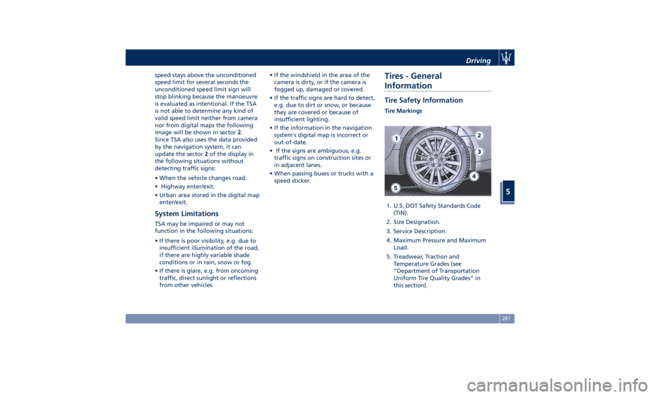
Information Tire Safety Information Tire Markings
1. U.S. DOT Safety Standards Code
(TIN).
2. Size Designation.
3. Service Description.
4. Maximum Pressure and Maximum
Load.
5. Treadwear, Traction and
Temperature Grades (see
“Department of Transportation
Uniform Tire Quality Grades” in
this section).Driving
5
281
Page 286 of 384
Tire Sizing Chart
EXAMPLE: P265/50 ZR19 (100Y) XL or
265/50 ZR19 (Y100) XL
Size Designation:
P = Passenger car tire size based on
U.S. design standards
“...blank...” = Passenger car tire
based on European design standards
265 = Section width in millimeters
(mm)
50 = Aspect ratio in percent (%) —
Ratio of section height to section
width of tire
ZR = Construction Code
• Z: means a tire usable at speeds
greater than 150 mph (240 km/h)
• R: means radial construction
19 = Rim diameter in inches (in) Service Description:
100 = Load Index — A numerical
code associated with the maximum
load a tire can carry
Y = Speed Symbol — A symbol
indicating the range of speeds at
which a tire can carry a load
corresponding to its load index
under certain operating conditions.
The maximum speed corresponding
to the speed symbol should only be
achieved under specified operating
conditions (i.e., tire pressure, vehicle
loading, road conditions, and posted
speed limits)
Load Identification:
“...blank...” = Absence of any text on
the sidewall of the tire indicates a
Standard Load (SL) tire
XL = Extra Load (or reinforced) tire
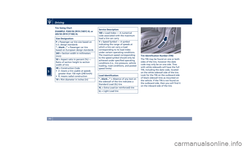
LL = Light Load tire Tire Identification Number (TIN)
The TIN may be found on one or both
sides of the tire, however the date
code may only be on one side. Tires
with white sidewalls will have the full
TIN, including the date code, located
on the white sidewall side of the tire.
Look for the TIN on the outboard side
of black sidewall tires as mounted on
the vehicle. If the TIN is not found on
the outboard side, then you will find it
on the inboard side of the tire.Driving
5
282
Page 288 of 384
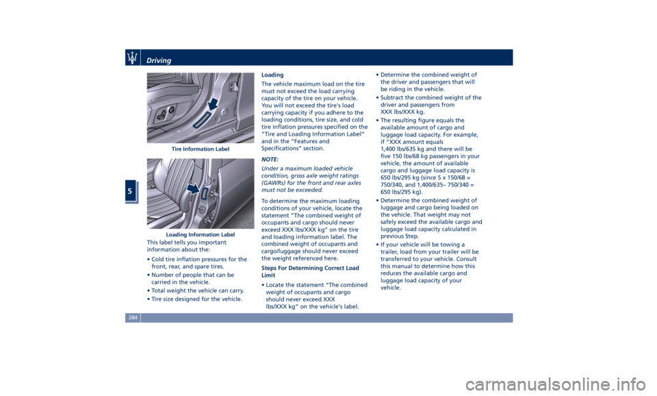
This label tells you important
information about the:
• Cold tire inflation pressures for the
front, rear, and spare tires.
• Number of people that can be
carried in the vehicle.
• Total weight the vehicle can carry.
• Tire size designed for the vehicle. Loading
The vehicle maximum load on the tire
must not exceed the load carrying
capacity of the tire on your vehicle.
You will not exceed the tire's load
carrying capacity if you adhere to the
loading conditions, tire size, and cold
tire inflation pressures specified on the
“Tire and Loading Information Label”
and in the “Features and
Specifications” section.
NOTE:
Under a maximum loaded vehicle
condition, gross axle weight ratings
(GAWRs) for the front and rear axles
must not be exceeded.
To determine the maximum loading
conditions of your vehicle, locate the
statement “The combined weight of
occupants and cargo should never
exceed XXX lbs/XXX kg” on the tire
and loading information label. The
combined weight of occupants and
cargo/luggage should never exceed
the weight referenced here.
Steps For Determining Correct Load
Limit
• Locate the statement “The combined
weight of occupants and cargo
should never exceed XXX
lbs/XXX kg” on the vehicle's label. • Determine the combined weight of
the driver and passengers that will
be riding in the vehicle.
• Subtract the combined weight of the
driver and passengers from
XXX lbs/XXX kg.
• The resulting figure equals the
available amount of cargo and
luggage load capacity. For example,
if “XXX amount equals
1,400 lbs/635 kg and there will be
five 150 lbs/68 kg passengers in your
vehicle, the amount of available
cargo and luggage load capacity is
650 lbs/295 kg (since 5 x 150/68 =
750/340, and 1,400/635– 750/340 =
650 lbs/295 kg).
• Determine the combined weight of
luggage and cargo being loaded on
the vehicle. That weight may not
safely exceed the available cargo and
luggage load capacity calculated in
previous Step.
• If your vehicle will be towing a
trailer, load from your trailer will be
transferred to your vehicle. Consult
this manual to determine how this
reduces the available cargo and
luggage load capacity of your
vehicle.Tire Information Label
Loading Information LabelDriving
5
284