buttons MASERATI GRANTURISMO 2019 Owners Manual
[x] Cancel search | Manufacturer: MASERATI, Model Year: 2019, Model line: GRANTURISMO, Model: MASERATI GRANTURISMO 2019Pages: 286, PDF Size: 8.08 MB
Page 32 of 286
CAUTION!
Volumetric and anti-lift protection
override is memorized until the alarm
is next activated; therefore, if this
protection is overridden but the alarm
is not activated immediately, the
override will remain memorized until
the next time it is activated, regardless
of turning the vehicle on/off.
Security Alarm Memory If the CODE warning light appears
on the display when the vehicle is
started, accompanied by the message
“Break-in attempt detected” this
means that an intrusion has been
attempted during your absence.
The security alarm system memory is
reset when you turn the ignition key. Requiring and Setting
Additional Key In order to purchase additional keys
with radio control you need to bring
with you at the Authorized Maserati
Dealer :
• all keys with radio control in your
possession;
• the Maserati CODE card;
• a personal ID;
• the identification and registration
documents proving ownership of the
vehicle.
Setting new keys with radio control or
re-setting the original ones may only
be performed at the Authorized
Maserati Dealer .
NOTE:
The codes of any key with radio
control that are not available when
the new setting procedure is carried
out will be deleted from the memory
to prevent any lost or stolen key with
radio control being used to disarm the
electronic alarm system. Radio Control Battery
Replacement If you press one of the three buttons
and this does not activate the
corresponding function, before
replacing the batteries, check for
correct operation of the security alarm
system functions using the other
remote control.
The recommended replaced battery
type is a: CR2032.
To replace the battery proceed as
follows:
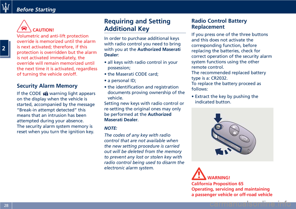
• Extract the key by pushing the
indicated button.
WARNING!
California Proposition 65
Operating, servicing and maintaining
a passenger vehicle or off-road vehicleBefore Starting
2
28
Page 36 of 286
Control Plus (MTC+) settings (see
"MTC+ Settings" in section
"Dashboard Instrument and
Controls").
If one or more doors are not properly
closed when locking the doors from
the outside, they will not be locked,
while if the trunk compartment is not
properly closed, the doors will in any
case be locked.
In both cases, the malfunction will be
indicated by the turn signals flashing
for a few seconds.
NOTE:
• The interior door locking/unlocking,
trunk compartment lid opening and
fuel tank door opening buttons are
disabled when the doors are locked
from the outside.
• In the event that the inertia switch
activates, the doors are electrically
unlocked and the vehicle can be
accessed by pressing the rear button
inside each handle.
Opening from the Inside To open the door, even if the lock is
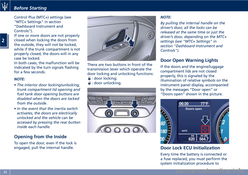
engaged, pull the internal handle. There are two buttons in front of the
transmission lever which operate the
door locking and unlocking functions:
: door locking;
: door unlocking. NOTE:
By pulling the internal handle on the
driver’s door, all the locks can be
released at the same time or just the
driver’s door, depending on the MTC+
settings (see "MTC+ Settings" in
section "Dashboard Instrument and
Controls").
Door Open Warning Lights If the doors and the engine/luggage
compartment lids are not closed
properly, this is signaled by the
illumination of relative symbols on the
instrument panel display, accompanied
by the messages “Door open” or
“Doors open” shown in the picture.
Door Lock ECU Initialization
Every time the battery is connected or
a fuse replaced, you must perform the
system initialization procedure toBefore Starting
2
32
Page 37 of 286
ensure proper system operation. To
perform this procedure, lock and then
unlock the doors using the buttons
and on the radio control device.
For more details, see "Maintenance-
Free Battery" in section "Maintenance
and Care".
Door Open Indicator Light Each door is provided with a reflector
fitted on the rear side of the door
panel that makes it visible when
illuminated by the headlights of a
vehicle.
Signal Upon exceeding a speed of 3 mph
(5 km/h), if one or more doors/lid are
open or not properly closed, a
warning signal will be activated.
Door Courtesy Light Each door panel is fitted with a
courtesy light, on the lower part of
the door framework, to illuminate the
area where passengers enter/exit the
vehicle. WARNING!
Gearshifting is always active and may
be performed even when one or more
doors, the engine compartment lid or
the trunk lid are open. Therefore, in
these conditions, take great care to
avoid moving the transmission shift
lever and so accidentally engage
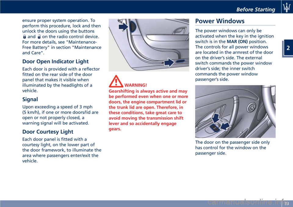
gears. Power Windows The power windows can only be
activated when the key in the ignition
switch is in the MAR (ON) position.
The controls for all power windows
are located in the armrest of the door
on the driver’s side. The external
switch commands the power window
driver’s side; the inner switch
commands the power window
passenger’s side.
The door on the passenger side only
has control for the window on the
passenger side.Before Starting
2
33
Page 75 of 286
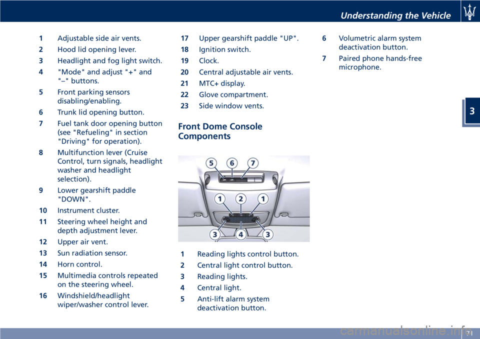
1 Adjustable side air vents.
2 Hood lid opening lever.
3 Headlight and fog light switch.
4 "Mode" and adjust "+" and
"–" buttons.
5 Front parking sensors
disabling/enabling.
6 Trunk lid opening button.
7 Fuel tank door opening button
(see "Refueling" in section
"Driving" for operation).
8 Multifunction lever (Cruise
Control, turn signals, headlight
washer and headlight
selection).
9 Lower gearshift paddle
"DOWN".
10 Instrument cluster.
11 Steering wheel height and
depth adjustment lever.
12 Upper air vent.
13 Sun radiation sensor.
14 Horn control.
15 Multimedia controls repeated
on the steering wheel.
16 Windshield/headlight
wiper/washer control lever. 17 Upper gearshift paddle "UP".
18 Ignition switch.
19 Clock.
20 Central adjustable air vents.
21 MTC+ display.
22 Glove compartment.
23 Side window vents.
Front Dome Console
Components
1 Reading lights control button.
2 Central light control button.
3 Reading lights.
4 Central light.
5 Anti-lift alarm system
deactivation button. 6 Volumetric alarm system
deactivation button.
7 Paired phone hands-free
microphone.
Understanding the Vehicle
3
71
Page 76 of 286
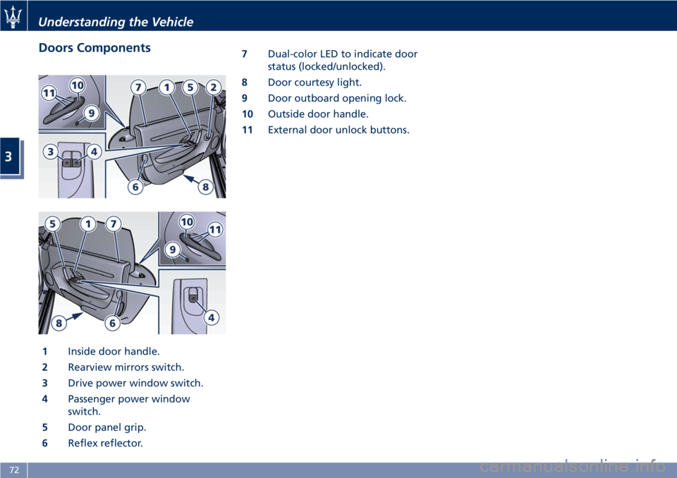
Doors Components
1 Inside door handle.
2 Rearview mirrors switch.
3 Drive power window switch.
4 Passenger power window
switch.
5 Door panel grip.
6 Reflex reflector. 7 Dual-color LED to indicate door
status (locked/unlocked).
8 Door courtesy light.
9 Door outboard opening lock.
10 Outside door handle.
11 External door unlock buttons.Understanding the Vehicle
3
72
Page 77 of 286
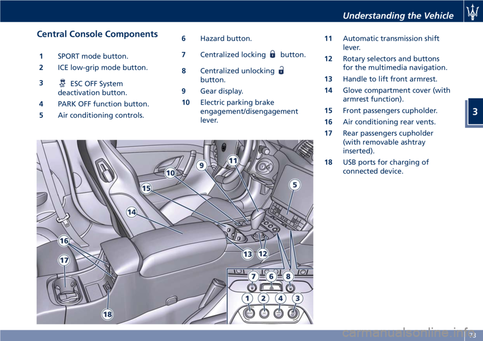
Central Console Components 1 SPORT mode button.
2 ICE low-grip mode button.
3
ESC OFF System
deactivation button.
4 PARK OFF function button.
5 Air conditioning controls. 6 Hazard button.
7 Centralized locking button.
8 Centralized unlocking
button.
9 Gear display.
10 Electric parking brake
engagement/disengagement
lever. 11 Automatic transmission shift
lever.
12 Rotary selectors and buttons
for the multimedia navigation.
13 Handle to lift front armrest.
14 Glove compartment cover (with
armrest function).
15 Front passengers cupholder.
16 Air conditioning rear vents.
17 Rear passengers cupholder
(with removable ashtray
inserted).
18 USB ports for charging of
connected device.Understanding the Vehicle
3
73
Page 81 of 286
will be felt within 2 to 5 minutes.
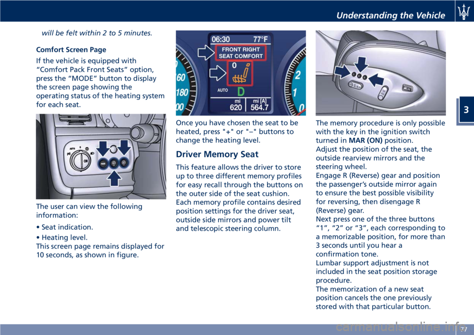
Comfort Screen Page
If the vehicle is equipped with
“Comfort Pack Front Seats” option,
press the “MODE” button to display
the screen page showing the
operating status of the heating system
for each seat.
The user can view the following
information:
• Seat indication.
• Heating level.
This screen page remains displayed for
10 seconds, as shown in figure. Once you have chosen the seat to be
heated, press "+" or "–" buttons to
change the heating level.
Driver Memory Seat This feature allows the driver to store
up to three different memory profiles
for easy recall through the buttons on
the outer side of the seat cushion.
Each memory profile contains desired
position settings for the driver seat,
outside side mirrors and power tilt
and telescopic steering column. The memory procedure is only possible
with the key in the ignition switch
turned in MAR (ON) position.
Adjust the position of the seat, the
outside rearview mirrors and the
steering wheel.
Engage R (Reverse) gear and position
the passenger’s outside mirror again
to ensure the best possible visibility
for reversing, then disengage R
(Reverse) gear.
Next press one of the three buttons
“1”, “2” or “3”, each corresponding to
a memorizable position, for more than
3 seconds until you hear a
confirmation tone.
Lumbar support adjustment is not
included in the seat position storage
procedure.
The memorization of a new seat
position cancels the one previously
stored with that particular button.Understanding the Vehicle
3
77
Page 82 of 286
To recall one of the stored positions
with the door open, press the relative
button “1”, “2” or “3” briefly.
To recall a stored position with the
door closed, press the corresponding
button until hearing a tone that
confirms the seat has stopped.
NOTE:
• To stop the seat, press one of the
buttons - “1”, “2” or “3” -, or one of
the adjustment controls.
• Malfunctioning of the seat control
unit is indicated by a sequence of 5
tones emitted when the key in the
ignition switch is turned to STOP
(OFF) position. Contact an
Authorized Maserati Dealer to have
the malfunction corrected.
Each system is independent of the
others and can be operated separately
using specific buttons for each seat.
System Initialization Procedure
Following any power cut-out (e.g.
after using the battery master switch
or dead battery), check the seats to
ensure that they are operating
properly when the power supply is
available.
Perform the following procedures on
both seats in the event of a
malfunction. The key in the ignition switch must be
in STOP (OFF) position and the door on
the side of the seat concerned closed.
Open the door and begin the
following procedure within 5 seconds,
then complete it within 10 seconds:
• forward - STOP;
• backward - STOP;
• forward - STOP;
• backward - STOP;
• tilt the seatback fully forward and
wait until the seat performs two
complete travels (forward and
backward);
• move the seatback to its normal
upright position.
NOTE:
If you need to disconnect the battery,
wait at least 30 seconds from the last
seat movement. If you disconnect the
battery before, you will have to run
the initialization procedure.
Seatback Facilitated Tilt
This function only active when the
door is open, moves the seat forward
automatically when the seatback is
reclined forward to facilitate access to
the rear seat or exiting the vehicle. The
seat returns to their original position
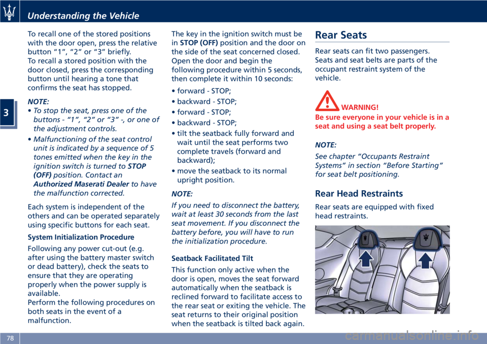
when the seatback is tilted back again. Rear Seats Rear seats can fit two passengers.
Seats and seat belts are parts of the
occupant restraint system of the
vehicle.
WARNING!
Be sure everyone in your vehicle is in a
seat and using a seat belt properly.
NOTE:
See
chapter “Occupants Restraint
Systems” in section “Before Starting”
for seat belt positioning.
Rear Head Restraints Rear seats are equipped with fixed
head restraints.Understanding the Vehicle
3
78
Page 92 of 286
CAUTION!
The high beams can only be switched
on manually by pushing the left-hand
multifunction lever forward.
WARNING!
If the high beams are activated, they
will turn on automatically every time
the low beams are switched on either
manually or automatically. We
recommend therefore that you switch
them off when they are no longer
necessary and every time the twilight
sensor deactivates the external lights.
“Follow me Home” Function
This
function allows you to set a
timing for activation of the position
lights and low beams, so that they may
remain on for a set time after turning
off the vehicle.
This function is activated by pushing
the left-hand multifunction lever on
the steering column, used to flash the
headlights.
The position lights and low beams turn
on for 30 seconds, the message
“Follow me” appears on the
instrument cluster display for 20 seconds, and the light activation time
is displayed.
When this function is active, every
time the left-hand multifunction lever
for flashing the headlights is operated,
the time the lights remain on is
increased by 30 seconds, with a
maximum total time of 210 seconds.
The display will show the time set.
If the left-hand multifunction lever for
flashing the headlights is operated for
more than 2 seconds, the function is
deactivated, and the indicator on the
instrument cluster display goes off.
When the function is active, turning
the key in the ignition switch back to
MAR (ON) position deactivates the
system.
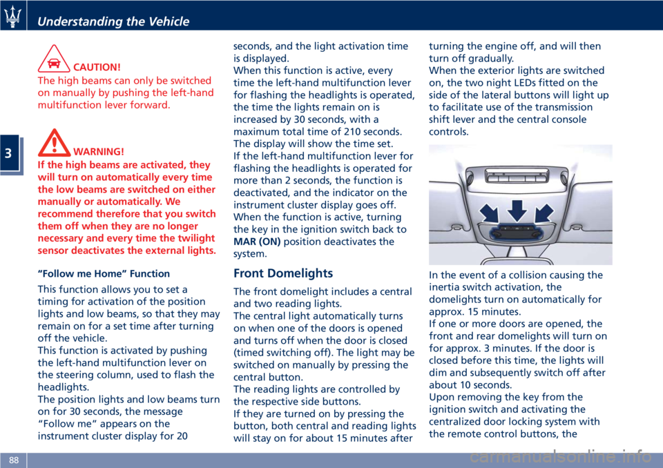
Front Domelights The front domelight includes a central
and two reading lights.
The central light automatically turns
on when one of the doors is opened
and turns off when the door is closed
(timed switching off). The light may be
switched on manually by pressing the
central button.
The reading lights are controlled by
the respective side buttons.
If they are turned on by pressing the
button, both central and reading lights
will stay on for about 15 minutes after turning the engine off, and will then
turn off gradually.
When the exterior lights are switched
on, the two night LEDs fitted on the
side of the lateral buttons will light up
to facilitate use of the transmission
shift lever and the central console
controls.
In the event of a collision causing the
inertia switch activation, the
domelights turn on automatically for
approx. 15 minutes.
If one or more doors are opened, the
front and rear domelights will turn on
for approx. 3 minutes. If the door is
closed before this time, the lights will
dim and subsequently switch off after
about 10 seconds.
Upon removing the key from the
ignition switch and activating the
centralized door locking system with
the remote control buttons, theUnderstanding the Vehicle
3
88
Page 102 of 286
The trunk is the most suitable place to
load bulky and heavy objects onboard
the vehicle.
To load your vehicle properly, store
heavier items below and be sure you
distribute their weight as evenly as
possible.
Stow all loose items securely before
start driving as they could move during
the trip.
HomeLink ®
(for
versions/markets, where
provided) HomeLink ®
replaces up to three
hand-held transmitters operating the
automatic devices that open garage
doors and gates, enable/disable the
lighting or security systems. The
HomeLink ®
unit is powered by your
vehicle's 12 Volt battery. The
HomeLink ®
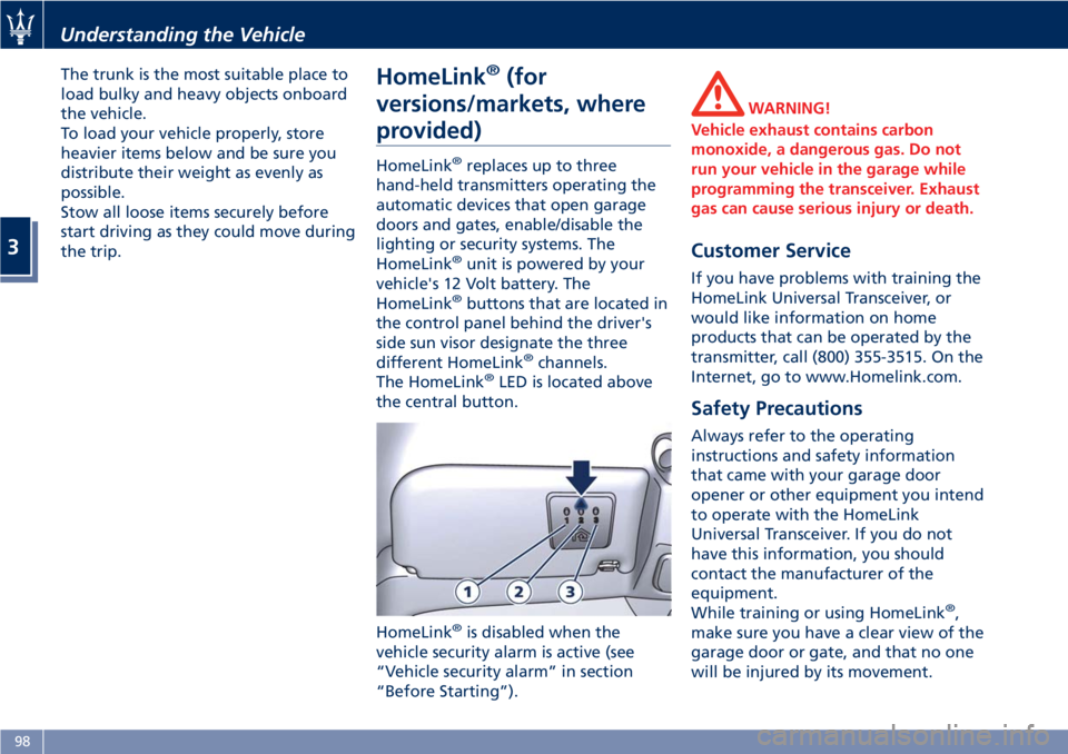
buttons that are located in
the control panel behind the driver's
side sun visor designate the three
different HomeLink ®
channels.
The HomeLink ®
LED is located above
the central button.
HomeLink ®
is disabled when the
vehicle security alarm is active (see
“Vehicle security alarm” in section
“Before Starting”). WARNING!
Vehicle exhaust contains carbon
monoxide, a dangerous gas. Do not
run your vehicle in the garage while
programming the transceiver. Exhaust
gas can cause serious injury or death.
Customer Service If you have problems with training the
HomeLink Universal Transceiver, or
would like information on home
products that can be operated by the
transmitter, call (800) 355-3515. On the
Internet, go to www.Homelink.com.
Safety Precautions Always refer to the operating
instructions and safety information
that came with your garage door
opener or other equipment you intend
to operate with the HomeLink
Universal Transceiver. If you do not
have this information, you should
contact the manufacturer of the
equipment.
While training or using HomeLink ®
,
make sure you have a clear view of the
garage door or gate, and that no one
will be injured by its movement.Understanding the Vehicle
3
98