door MASERATI GRANTURISMO 2020 Owner's Manual
[x] Cancel search | Manufacturer: MASERATI, Model Year: 2020, Model line: GRANTURISMO, Model: MASERATI GRANTURISMO 2020Pages: 286, PDF Size: 6.7 MB
Page 71 of 286
•Never place or install floor mats or
other floor coverings in the vehicle
that cannot be properly secured to
prevent them from moving and
interfering with the pedals.
•Never put floor mats or other floor
coverings on top of already installed
floor mats. Additional floor mats
and other coverings will reduce the
size of the pedal area and interfere
with the pedals.
•Check mounting of mats on a
regular basis. Always properly
reinstall and secure floor mats that
have been removed for cleaning.
•Always make sure that objects
cannot fall into the driver footwell
while the vehicle is moving. Objects
can become trapped under the
brake pedal and accelerator pedal
causing a loss of vehicle control.
•Mounting posts must be properly
installed, if not equipped from the
factory. Failure to properly follow
floor mat installation or mounting
can cause interference with the
brake pedal and accelerator pedal
operation causing loss of control of
the vehicle.Tires
• Examine tires for excessive tread
wear and uneven wear patterns.
• Check for stones, nails, glass, or
other objects lodged in the tread or
sidewall.
• Inspect the tread for cuts and cracks.
• Inspect sidewalls for cuts, cracks and
bulges.
• Check the wheel nuts for tightness.
• Check the tires (see “Tire Inflation
Pressure” chapter in section
“Features and Specifications”) for
proper cold inflation pressure.
Lights and Indicator Lights
• Have someone observe the
operation of exterior lights while
you operate the controls (see
“Lights” chapter in section
“Understanding the Vehicle”).
• Check turn signal and high beam
indicator lights on the instrument
cluster (see “Instrument Cluster”
chapter in section “Dashboard
Instruments and Controls”).
Door Latches
• Check for positive closing, latching,
and locking of doors and trunk lid
(see chapter “Doors” and “Open and
Close the Trunk Lid” in this section).Fluid Leaks
• Check area under vehicle after
overnight parking for recent fluid
leaks (oil, fuel, etc.).
• If gasoline fumes are detected or
fluid leaks are suspected, contact an
Authorized Maserati Dealer.
WARNING!
California Proposition 65
Operating, servicing and maintaining
a passenger vehicle or off-road vehicle
can expose you to chemicals including
such as, engine exhaust, carbon
monoxide, phthalates and lead, that
which are know to the State of
California to cause cancer and birth
defects or other reproductive harm. To
minimize exposure, avoid breathing
exhaust, do not idle the engine except
as necessary, service your vehicle in a
well-ventilated area and wear gloves
or wash your hands frequently when
servicing your vehicle. For more
information go to:
www.P65Warnings.ca.gov/passenger-
vehicle
Before Starting
2
67
Page 75 of 286
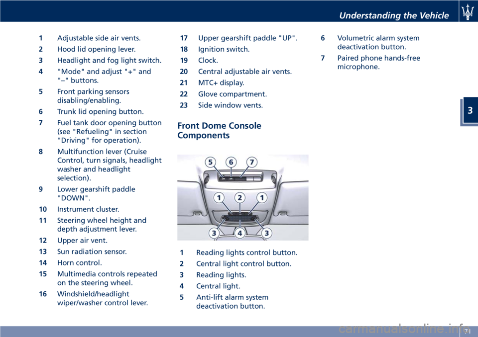
1Adjustable side air vents.
2Hood lid opening lever.
3Headlight and fog light switch.
4"Mode" and adjust "+" and
"–" buttons.
5Front parking sensors
disabling/enabling.
6Trunk lid opening button.
7Fuel tank door opening button
(see "Refueling" in section
"Driving" for operation).
8Multifunction lever (Cruise
Control, turn signals, headlight
washer and headlight
selection).
9Lower gearshift paddle
"DOWN".
10Instrument cluster.
11Steering wheel height and
depth adjustment lever.
12Upper air vent.
13Sun radiation sensor.
14Horn control.
15Multimedia controls repeated
on the steering wheel.
16Windshield/headlight
wiper/washer control lever.17Upper gearshift paddle "UP".
18Ignition switch.
19Clock.
20Central adjustable air vents.
21MTC+ display.
22Glove compartment.
23Side window vents.
Front Dome Console
Components
1Reading lights control button.
2Central light control button.
3Reading lights.
4Central light.
5Anti-lift alarm system
deactivation button.6Volumetric alarm system
deactivation button.
7Paired phone hands-free
microphone.
Understanding the Vehicle
3
71
Page 76 of 286
Doors Components
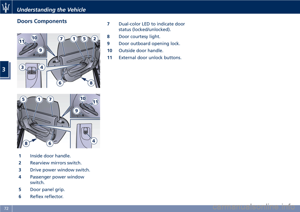
1Inside door handle.
2Rearview mirrors switch.
3Drive power window switch.
4Passenger power window
switch.
5Door panel grip.
6Reflex reflector.7Dual-color LED to indicate door
status (locked/unlocked).
8Door courtesy light.
9Door outboard opening lock.
10Outside door handle.
11External door unlock buttons.
Understanding the Vehicle
3
72
Page 78 of 286
Front Seats
Seats and seat belts are part of the
Occupant Restraint System of the
vehicle. For further information, see
chapter “Occupant Restraint System”
in Section “Before Starting”.
WARNING!
Be sure everyone in your vehicle is in a
seat and using a seat belt properly.
Seat Adjustments
The seats can only be adjusted with
the key in the ignition switch inMAR
(ON)position.
It is however possible, when the door
is closed, to operate the seat for
approx. 15 seconds after turning the
key toSTOP (OFF)position and then
for other 15 seconds after the last
operation.
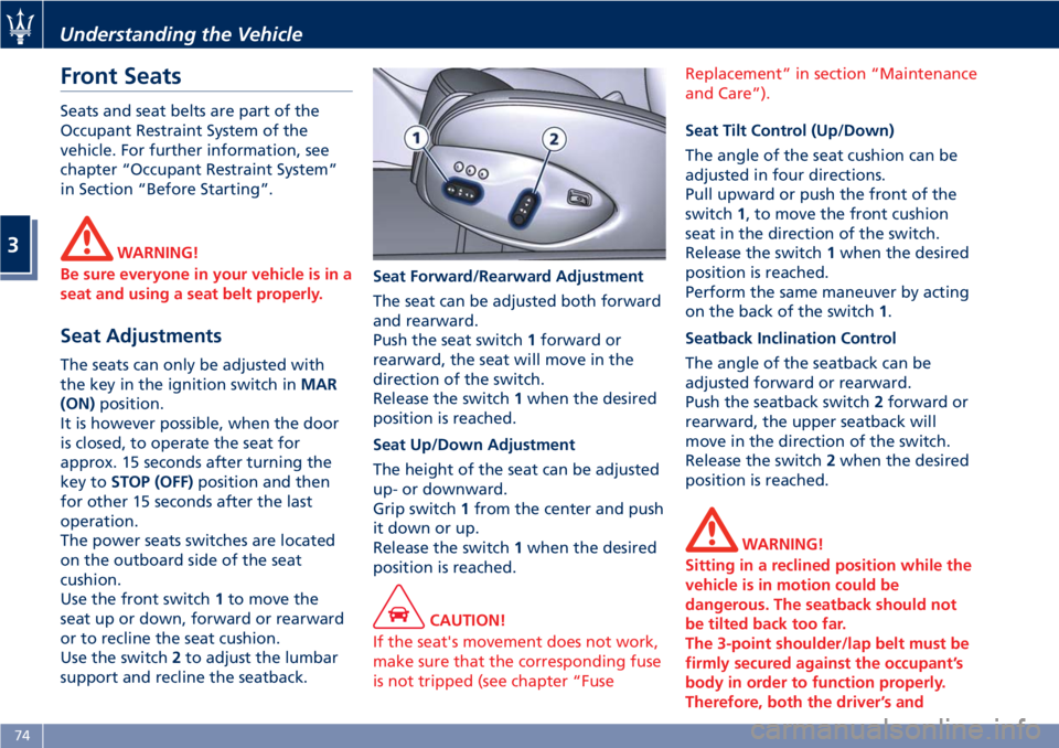
The power seats switches are located
on the outboard side of the seat
cushion.
Use the front switch1to move the
seat up or down, forward or rearward
or to recline the seat cushion.
Use the switch2to adjust the lumbar
support and recline the seatback.Seat Forward/Rearward Adjustment
The seat can be adjusted both forward
and rearward.
Push the seat switch1forward or
rearward, the seat will move in the
direction of the switch.
Release the switch1when the desired
position is reached.
Seat Up/Down Adjustment
The height of the seat can be adjusted
up- or downward.
Grip switch1from the center and push
it down or up.
Release the switch1when the desired
position is reached.
CAUTION!
If the seat's movement does not work,
make sure that the corresponding fuse
is not tripped (see chapter “FuseReplacement” in section “Maintenance
and Care”).
Seat Tilt Control (Up/Down)
The angle of the seat cushion can be
adjusted in four directions.
Pull upward or push the front of the
switch1, to move the front cushion
seat in the direction of the switch.
Release the switch1when the desired
position is reached.
Perform the same maneuver by acting
on the back of the switch1.
Seatback Inclination Control
The angle of the seatback can be
adjusted forward or rearward.
Push the seatback switch2forward or
rearward, the upper seatback will
move in the direction of the switch.
Release the switch2when the desired
position is reached.
WARNING!
Sitting in a reclined position while the
vehicle is in motion could be
dangerous. The seatback should not
be tilted back too far.
The 3-point shoulder/lap belt must be
firmly secured against the occupant’s
body in order to function properly.
Therefore, both the driver’s and
Understanding the Vehicle
3
74
Page 82 of 286
To recall one of the stored positions
with the door open, press the relative
button “1”, “2” or “3” briefly.
To recall a stored position with the
door closed, press the corresponding
button until hearing a tone that
confirms the seat has stopped.
NOTE:
•To stop the seat, press one of the
buttons - “1”, “2” or “3” -, or one of
the adjustment controls.
•Malfunctioning of the seat control
unit is indicated by a sequence of 5
tones emitted when the key in the
ignition switch is turned toSTOP
(OFF)position. Contact an
Authorized Maserati Dealerto have
the malfunction corrected.
Each system is independent of the
others and can be operated separately
using specific buttons for each seat.
System Initialization Procedure
Following any power cut-out (e.g.
after using the battery master switch
or dead battery), check the seats to
ensure that they are operating
properly when the power supply is
available.
Perform the following procedures on
both seats in the event of a
malfunction.The key in the ignition switch must be
inSTOP (OFF)position and the door on
the side of the seat concerned closed.
Open the door and begin the
following procedure within 5 seconds,
then complete it within 10 seconds:
• forward - STOP;
• backward - STOP;
• forward - STOP;
• backward - STOP;
• tilt the seatback fully forward and
wait until the seat performs two
complete travels (forward and
backward);
• move the seatback to its normal
upright position.
NOTE:
If you need to disconnect the battery,
wait at least 30 seconds from the last
seat movement. If you disconnect the
battery before, you will have to run
the initialization procedure.
Seatback Facilitated Tilt
This function only active when the
door is open, moves the seat forward
automatically when the seatback is
reclined forward to facilitate access to
the rear seat or exiting the vehicle. The
seat returns to their original position
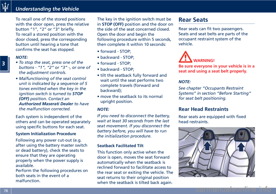
when the seatback is tilted back again.Rear Seats
Rear seats can fit two passengers.
Seats and seat belts are parts of the
occupant restraint system of the
vehicle.
WARNING!
Be sure everyone in your vehicle is in a
seat and using a seat belt properly.
NOTE:
See chapter “Occupants Restraint
Systems” in section “Before Starting”
for seat belt positioning.
Rear Head Restraints
Rear seats are equipped with fixed
head restraints.
Understanding the Vehicle
3
78
Page 84 of 286
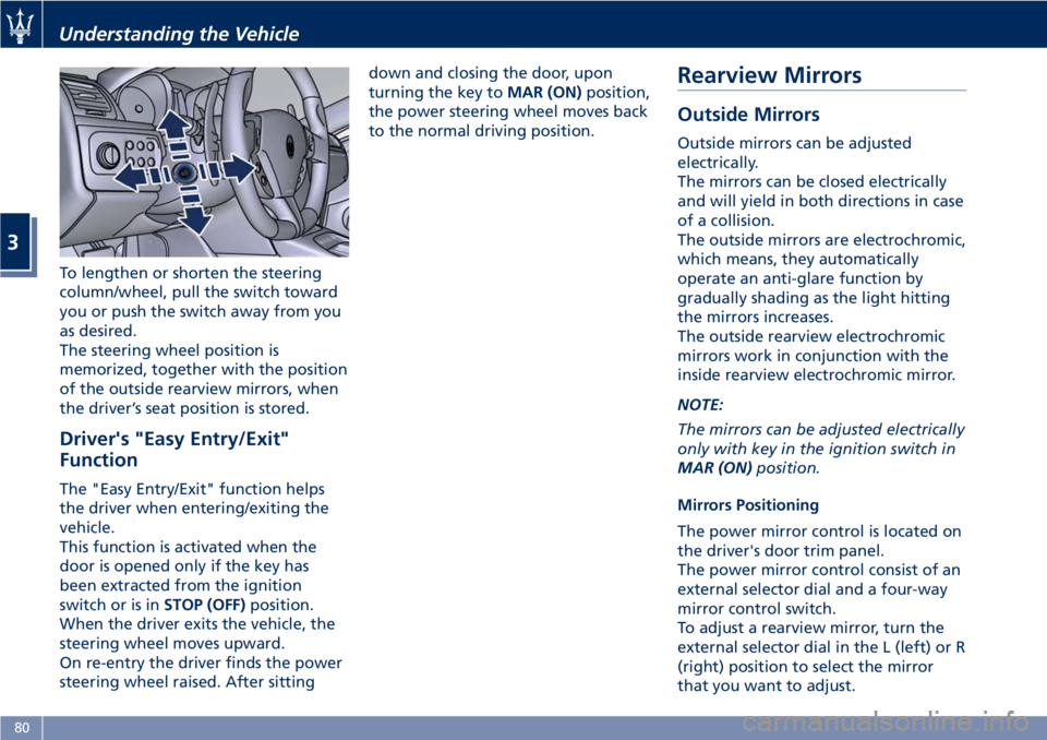
To lengthen or shorten the steering
column/wheel, pull the switch toward
you or push the switch away from you
as desired.
The steering wheel position is
memorized, together with the position
of the outside rearview mirrors, when
the driver’s seat position is stored.
Driver's "Easy Entry/Exit"
Function
The "Easy Entry/Exit" function helps
the driver when entering/exiting the
vehicle.
This function is activated when the
door is opened only if the key has
been extracted from the ignition
switch or is inSTOP (OFF)position.
When the driver exits the vehicle, the
steering wheel moves upward.
On re-entry the driver finds the power
steering wheel raised. After sittingdown and closing the door, upon
turning the key toMAR (ON)position,
the power steering wheel moves back
to the normal driving position.
Rearview Mirrors
Outside Mirrors
Outside mirrors can be adjusted
electrically.
The mirrors can be closed electrically
and will yield in both directions in case
of a collision.
The outside mirrors are electrochromic,
which means, they automatically
operate an anti-glare function by
gradually shading as the light hitting
the mirrors increases.
The outside rearview electrochromic
mirrors work in conjunction with the
inside rearview electrochromic mirror.
NOTE:
The mirrors can be adjusted electrically
only with key in the ignition switch in
MAR (ON)position.
Mirrors Positioning
The power mirror control is located on
the driver's door trim panel.
The power mirror control consist of an
external selector dial and a four-way
mirror control switch.
To adjust a rearview mirror, turn the
external selector dial in the L (left) or R
(right) position to select the mirror
that you want to adjust.
Understanding the Vehicle
3
80
Page 92 of 286
CAUTION!
The high beams can only be switched
on manually by pushing the left-hand
multifunction lever forward.
WARNING!
If the high beams are activated, they
will turn on automatically every time
the low beams are switched on either
manually or automatically. We
recommend therefore that you switch
them off when they are no longer
necessary and every time the twilight
sensor deactivates the external lights.
“Follow me Home” Function
This function allows you to set a
timing for activation of the position
lights and low beams, so that they may
remain on for a set time after turning
off the vehicle.
This function is activated by pushing
the left-hand multifunction lever on
the steering column, used to flash the
headlights.
The position lights and low beams turn
on for 30 seconds, the message
“Follow me” appears on the
instrument cluster display for 20seconds, and the light activation time
is displayed.
When this function is active, every
time the left-hand multifunction lever
for flashing the headlights is operated,
the time the lights remain on is
increased by 30 seconds, with a
maximum total time of 210 seconds.
The display will show the time set.
If the left-hand multifunction lever for
flashing the headlights is operated for
more than 2 seconds, the function is
deactivated, and the indicator on the
instrument cluster display goes off.
When the function is active, turning
the key in the ignition switch back to
MAR (ON)position deactivates the
system.Front Domelights
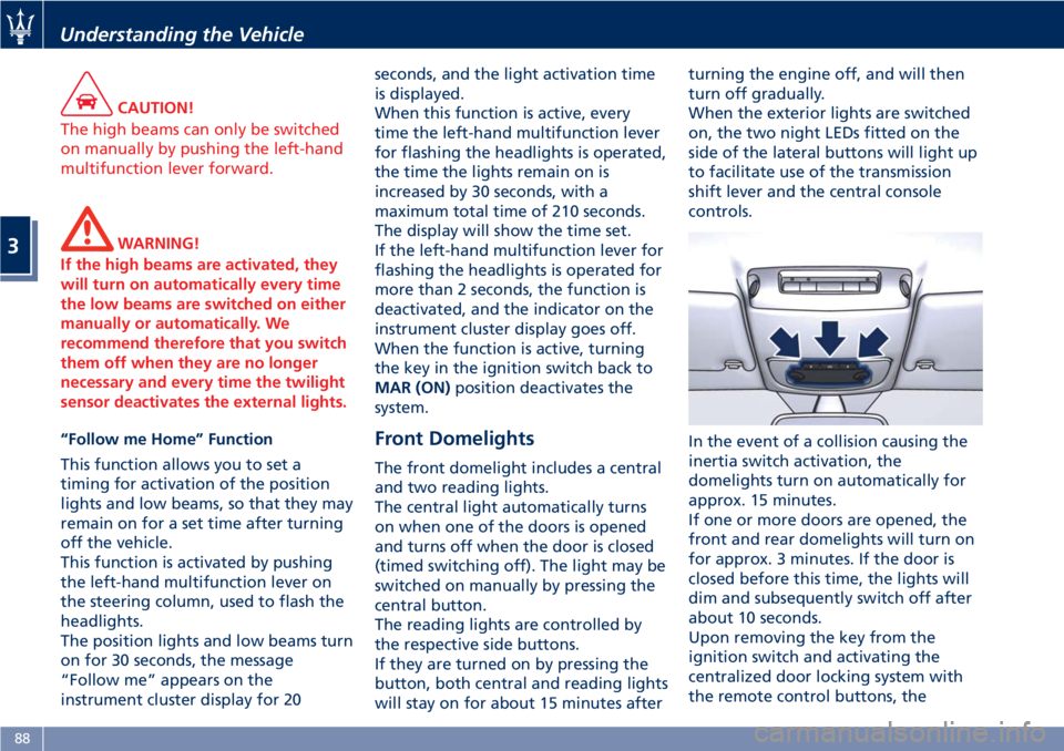
The front domelight includes a central
and two reading lights.
The central light automatically turns
on when one of the doors is opened
and turns off when the door is closed
(timed switching off). The light may be
switched on manually by pressing the
central button.
The reading lights are controlled by
the respective side buttons.
If they are turned on by pressing the
button, both central and reading lights
will stay on for about 15 minutes afterturning the engine off, and will then
turn off gradually.
When the exterior lights are switched
on, the two night LEDs fitted on the
side of the lateral buttons will light up
to facilitate use of the transmission
shift lever and the central console
controls.
In the event of a collision causing the
inertia switch activation, the
domelights turn on automatically for
approx. 15 minutes.
If one or more doors are opened, the
front and rear domelights will turn on
for approx. 3 minutes. If the door is
closed before this time, the lights will
dim and subsequently switch off after
about 10 seconds.
Upon removing the key from the
ignition switch and activating the
centralized door locking system with
the remote control buttons, the
Understanding the Vehicle
3
88
Page 93 of 286
domelights turn on for about 10
seconds.
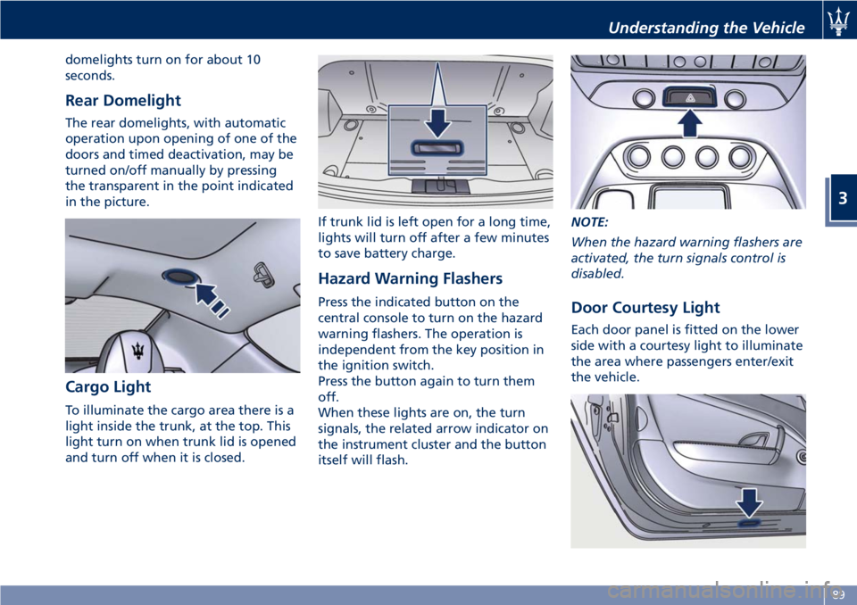
Rear Domelight
The rear domelights, with automatic
operation upon opening of one of the
doors and timed deactivation, may be
turned on/off manually by pressing
the transparent in the point indicated
in the picture.
Cargo Light
To illuminate the cargo area there is a
light inside the trunk, at the top. This
light turn on when trunk lid is opened
and turn off when it is closed.If trunk lid is left open for a long time,
lights will turn off after a few minutes
to save battery charge.
Hazard Warning Flashers
Press the indicated button on the
central console to turn on the hazard
warning flashers. The operation is
independent from the key position in
the ignition switch.
Press the button again to turn them
off.
When these lights are on, the turn
signals, the related arrow indicator on
the instrument cluster and the button
itself will flash.NOTE:
When the hazard warning flashers are
activated, the turn signals control is
disabled.Door Courtesy Light
Each door panel is fitted on the lower
side with a courtesy light to illuminate
the area where passengers enter/exit
the vehicle.
Understanding the Vehicle
3
89
Page 101 of 286
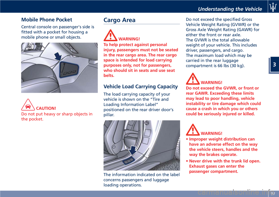
Mobile Phone Pocket
Central console on passenger's side is
fitted with a pocket for housing a
mobile phone or small objects.
CAUTION!
Do not put heavy or sharp objects in
the pocket.
Cargo Area
WARNING!
To help protect against personal
injury, passengers must not be seated
in the rear cargo area. The rear cargo
space is intended for load carrying
purposes only, not for passengers,
who should sit in seats and use seat
belts.
Vehicle Load Carrying Capacity
The load carrying capacity of your
vehicle is shown on the “Tire and
Loading Information Label”
positioned on the rear driver door's
pillar.
The information indicated on the label
concerns passengers and luggage
loading operations.Do not exceed the specified Gross
Vehicle Weight Rating (GVWR) or the
Gross Axle Weight Rating (GAWR) for
either the front or rear axle.
The GVWR is the total allowable
weight of your vehicle. This includes
driver, passengers, and cargo.
The maximum load which may be
carried in the rear luggage
compartment is 66 lbs (30 kg).
WARNING!
Do not exceed the GVWR, or front or
rear GAWR. Exceeding these limits
may lead to poor handling, vehicle
instability or tire damage which could
cause a crash in which you or others
could be seriously injured or killed.
WARNING!
•Improper weight distribution can
have an adverse effect on the way
the vehicle steers, handles and the
way the brakes operate.
•Never drive with the trunk lid open.
Exhaust gases can enter the
passenger compartment.
Understanding the Vehicle
3
97
Page 102 of 286
The trunk is the most suitable place to
load bulky and heavy objects onboard
the vehicle.
To load your vehicle properly, store
heavier items below and be sure you
distribute their weight as evenly as
possible.
Stow all loose items securely before
start driving as they could move during
the trip.HomeLink®(for
versions/markets, where
provided)
HomeLink®replaces up to three
hand-held transmitters operating the
automatic devices that open garage
doors and gates, enable/disable the
lighting or security systems. The
HomeLink
®unit is powered by your
vehicle's 12 Volt battery. The
HomeLink
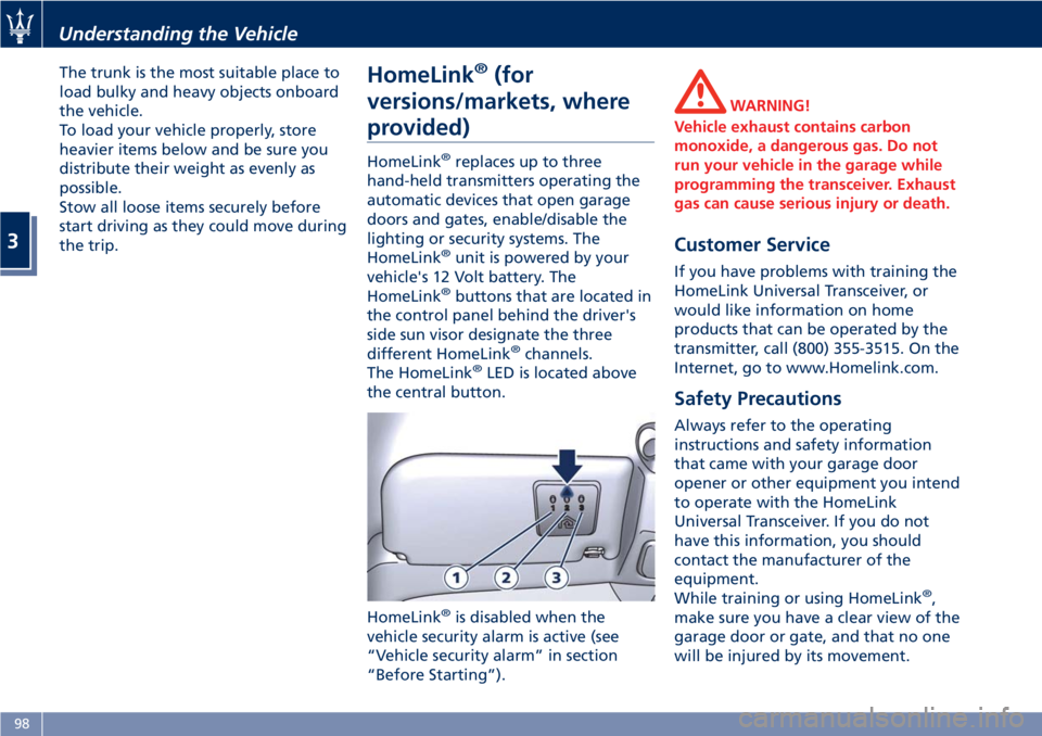
®buttons that are located in
the control panel behind the driver's
side sun visor designate the three
different HomeLink
®channels.
The HomeLink®LED is located above
the central button.
HomeLink
®is disabled when the
vehicle security alarm is active (see
“Vehicle security alarm” in section
“Before Starting”).
WARNING!
Vehicle exhaust contains carbon
monoxide, a dangerous gas. Do not
run your vehicle in the garage while
programming the transceiver. Exhaust
gas can cause serious injury or death.
Customer Service
If you have problems with training the
HomeLink Universal Transceiver, or
would like information on home
products that can be operated by the
transmitter, call (800) 355-3515. On the
Internet, go to www.Homelink.com.
Safety Precautions
Always refer to the operating
instructions and safety information
that came with your garage door
opener or other equipment you intend
to operate with the HomeLink
Universal Transceiver. If you do not
have this information, you should
contact the manufacturer of the
equipment.
While training or using HomeLink
®,
make sure you have a clear view of the
garage door or gate, and that no one
will be injured by its movement.
Understanding the Vehicle
3
98