door MASERATI GRANTURISMO 2020 Service Manual
[x] Cancel search | Manufacturer: MASERATI, Model Year: 2020, Model line: GRANTURISMO, Model: MASERATI GRANTURISMO 2020Pages: 286, PDF Size: 6.7 MB
Page 184 of 286
All passenger car tires must conform to
Federal safety requirements in
addition to these grades.
Treadwear
The Treadwear grade is a comparative
rating, based on the wear rate of the
tire when tested under controlled
conditions on a specified government
test course. For example, a tire graded
150 would wear one and one-half
times as well on the government
course as a tire graded 100. The
relative performance of tires depends
upon the actual conditions of their
use, however, and may depart
significantly from the norm due to
variations in driving habits, service
practices, and differences in road
characteristics and climate.
Traction Grades
The Traction grades, from highest to
lowest, are AAA, A, B, and C. These
grades represent the tire's ability to
stop on wet pavement, as measured
under controlled conditions on
specified government test surfaces of
asphalt and concrete. A tire marked C
may have poor traction performance.
WARNING!
The traction grade assigned to this tire
is based on straight-ahead braking
traction tests, and does not include
acceleration, cornering, hydroplaning,
or peak traction characteristics.
Temperature Grades
The temperature grades are A (the
highest), B, and C, representing the
tire's resistance to the generation of
heat and its ability to dissipate heat,
when tested under controlled
conditions on a specified indoor
laboratory test wheel. Sustained high
temperature can cause the material of
the tire to degenerate and reduce tire
life, and excessive temperature can
lead to sudden tire failure. The grade
C corresponds to a level of
performance, which all passenger car
tires must meet under the Federal
Motor Vehicle Safety Standard No.
109. Grades B and A represent higher
levels of performance on the
laboratory test wheel, than the
minimum required by law.
WARNING!
The temperature grade for this tire isestablished for a tire that is properly
inflated and not overloaded. Excessive
speed, under-inflation, or excessive
loading, either separately or in
combination, can cause heat buildup
and possible tire failure.
Tire Pressure
Proper tire inflation pressure is
essential for safety and best
performance of your vehicle. The tire
pressure monitoring system “TPMS”
setup on the vehicle (see “Tire Pressure
Monitoring System” in this section)
may alert the driver about insufficient
tire pressure even though the driver is
responsible for regularly checking the
tire pressure.
Radial tires fitted on the vehicle may
look properly inflated even when they
actually are under inflated. Do not
make a visual judgment when
determining proper inflation.
Three primary driving aspects are
affected by improper tire pressure:
Safety
WARNING!
•Improperly inflated tires can be
dangerous.
Driving
5
180
Page 185 of 286
•Under-inflation increases tire flexing
and can result in tire overheating.
•Over-inflation reduces a tire's ability
to cushion shock. Objects on the
road and potholes can cause
damage that results in tire failure.
•Over-inflated or under-inflated tires
can affect vehicle handling and can
fail suddenly, resulting in loss of
vehicle control.
•Unequal tire pressures can cause
steering problems.
•Unequal tire pressures from one side
of the vehicle to the other can cause
the vehicle to drift to the right or
left.
•Always drive with each tire inflated
to the recommended cold tire
inflation pressure.
Economy
Improper inflation pressures may
cause uneven wear patterns to
develop across the tire tread. These
abnormal wear patterns will reduce
tread life resulting in a need for
earlier tire replacement. Under-
inflation also increases tire rolling
resistance resulting in higher fuel
consumption.Ride comfort and vehicle stability
Proper tire inflation contributes to a
comfortable ride. Over-inflation
produces a jarring and uncomfortable
ride.
Tire Pressure Checkup
The proper cold tire inflation pressure
is indicated on the driver's side rear
door pillar and on the table “Tire
Inflation Pressure” in section
“Features and Specifications”.
Inflation pressure specified on the
table always refers to “cold tire
inflation pressure”. Cold tire inflation
pressure is defined as the tire pressure
after the vehicle has not been driven
for at least three hours, or driven less
than 1 mi (1,6 km) after a three hour
period.
Check tire pressures more often in
case of significant outside
temperature changes, as tire pressure
varies according to temperature
changes.
The pressure should be checked and if
necessary adjusted; tire wear and
overall conditions should also be
checked monthly. Tire pressures
change by approximately 1 PSI (0,07
bar) per 12°F (7°C) of air temperature
change. Keep this in mind whenchecking tire pressure inside a garage,
especially in winter.
Example: If garage temperature = 68°F
(20°C) and the outside temperature =
32°F (0°C) then the cold tire inflation
pressure should be increased by 3 PSI
(0,21 bar) for every 12°F (7°C) for this
outside temperature condition.
Tire pressure may increase from 2 to 6
PSI (0,13 to 0,4 bar) during operation.
DO NOT reduce this normal pressure
build-up or your tire pressure will be
too low. After inspecting or adjusting
the tire pressure, always reinstall the
valve stem cap. This will prevent
moisture and dirt from entering the
valve stem, which could damage the
valve stem and the TPMS sensor
connected to it.
Tread Wear Indicators
Tread wear indicators are in the
original equipment tires to help you
determine when your tires should be
replaced.
These indicators are molded into the
bottom of the tread grooves.
When the tread is worn to one of the
tread wear indicators, the tire should
be replaced.
Driving
5
181
Page 186 of 286
WARNING!
The wet performance (aquaplaning
resistance) will decrease
proportionally to the thickness of the
tread.
Tires Durability
The service life of a tire depends on
various factors including, but not
limited to:
• driving style;
• tire pressure;
• distance driven.
WARNING!
Tires and the spare tire (if equipped)
should be replaced after six years,
regardless of the remaining tread.
Failure to follow this warning could
result in tire failure.
Replacement Tires
NOTE:
In order to maintain high performance
and safety level under all driving
conditions, Maserati strongly
recommends to use tires equivalent to
the originals in size, quality and
performance when replacement is
needed.
For the size designation of your tire
see the label on the driver's side rear
door pillar or see table “Wheels” in
section “Features and Specifications”.
The “Load Index” and “Speed Symbol”
for your tire will be found on the
original equipment tire sidewall.
It is recommended to replace the two
front tires or two rear tires as a pair.
Replacing just one tire can seriously
affect your vehicle’s handling.
If you ever replace a wheel assembly,
make sure that the wheel’s
specifications (valve, TPMS sensor and
tire) match those of the original
wheels. Failure to use equivalent
replacement tires may adversely affect
the safety, handling, and ride of your
vehicle.
YourAuthorized Maserati Dealeris
available to provide suggestions as tothe types of tires most suited to the
use foreseen by the Customer.
WARNING!
•Do not use a tire, wheel size or
rating other than that specified for
your vehicle. Some combinations of
unapproved tires and wheels may
change suspension dimensions and
performance characteristics,
resulting in altered steering,
handling, and braking operations of
the vehicle. This can cause
unpredictable handling and stress to
steering and suspension
components. Use only the tire and
wheel sizes with load ratings
appointed for your vehicle.
•Never use a tire with a smaller load
index or capacity, other than what
was originally equipped on your
vehicle. Using a tire with a smaller
load index could result in tire
overloading and failure.
•Always check the maximum speed
rating on the tire sidewall on any
tire on the vehicle.
•Never exceed the maximum speed
rating of the tires. Risk of accident
and serious personal injury due to
excessive speed.
Driving
5
182
Page 188 of 286
NOTE:
TheAuthorized Maserati Dealercan
provide you with all information about
the Maserati Snow Chains, available in
the "Genuine Accessories" range.Tire Pressure Monitoring
System - TPMS
Guidelines
Each tire (including the spare tire, if
provided) should be checked monthly.
Tires should be checked when cold and
inflated to the inflation pressure
recommended by the vehicle
manufacturer indicated on tire
inflation pressure label (applied on the
driver's rear door pillar) and in “Tire
Inflation Pressure” of section “Features
and Specifications”.
If your vehicle has tires of a different
size than the size indicated on the
vehicle placard or tire inflation
pressure label, you should determine
the proper tire inflation pressure for
those tires.
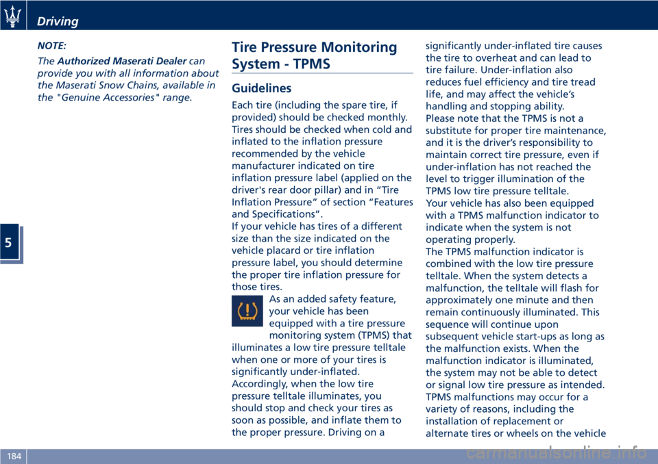
As an added safety feature,
your vehicle has been
equipped with a tire pressure
monitoring system (TPMS) that
illuminates a low tire pressure telltale
when one or more of your tires is
significantly under-inflated.
Accordingly, when the low tire
pressure telltale illuminates, you
should stop and check your tires as
soon as possible, and inflate them to
the proper pressure. Driving on asignificantly under-inflated tire causes
the tire to overheat and can lead to
tire failure. Under-inflation also
reduces fuel efficiency and tire tread
life, and may affect the vehicle’s
handling and stopping ability.
Please note that the TPMS is not a
substitute for proper tire maintenance,
and it is the driver’s responsibility to
maintain correct tire pressure, even if
under-inflation has not reached the
level to trigger illumination of the
TPMS low tire pressure telltale.
Your vehicle has also been equipped
with a TPMS malfunction indicator to
indicate when the system is not
operating properly.
The TPMS malfunction indicator is
combined with the low tire pressure
telltale. When the system detects a
malfunction, the telltale will flash for
approximately one minute and then
remain continuously illuminated. This
sequence will continue upon
subsequent vehicle start-ups as long as
the malfunction exists. When the
malfunction indicator is illuminated,
the system may not be able to detect
or signal low tire pressure as intended.
TPMS malfunctions may occur for a
variety of reasons, including the
installation of replacement or
alternate tires or wheels on the vehicle
Driving
5
184
Page 189 of 286
that prevent the TPMS from
functioning properly. Always check the
TPMS malfunction telltale after
replacing one or more tires or wheels
on your vehicle to ensure that the
replacement or alternate tires and
wheels allow the TPMS to continue to
function properly.
General Information
The Tire Pressure Monitoring System
(TPMS) will warn the driver of a low
tire pressure according to the vehicle
recommended cold pressure indicated
on the table “Tire Inflation Pressure”
in section “Features and
Specifications” and on the label
applied on the driver's side at the base
of the rear door pillar.
The cold tire inflation pressure must
not exceed the maximum inflation
pressure molded into the tire sidewall.
Check “Tires – General Information” in
section “Driving” for information on
how to properly inflate the tires.
The tire pressure will also increase as
the vehicle is driven - this is normal
and there is no adjustment required
when this occurs.
The TPMS will warn the driver of a low
tire pressure if the tire pressure falls
below the low-pressure warning limit
for any reason, including lowtemperature effects and natural
pressure loss of the tire.
The TPMS will continue to warn the
driver of low tire pressure as long as
the condition persists and will not turn
off until the tire pressure is equal or
above the recommended cold
inflation pressure.
The TPMS monitors the tire pressure
by means of special sensors fitted
inside the wheel rims, in position with
the inflation valve.
These sensors transmit a signal that is
detected by the antenna integrated in
the ECU.
The ECU processes this information
and, via the CAN line, transmits a
series of tire pressure data and system
errors, if any, to the instrument cluster.
The display may show the information
received by means of specific screen
pages, which can be recalled by
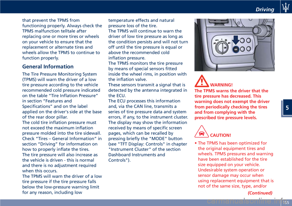
pressing briefly the "MODE" button
(see "TFT Display: Controls" in chapter
"Instrument Cluster" of the section
Dashboard Instruments and
Controls").
WARNING!
The TPMS warns the driver that the
tire pressure has decreased. This
warning does not exempt the driver
from periodically checking the tires
and from complying with the
prescribed tire pressure levels.
CAUTION!
• The TPMS has been optimized for
the original equipment tires and
wheels. TPMS pressures and warning
have been established for the tire
size equipped on your vehicle.
Undesirable system operation or
sensor damage may occur when
using replacement equipment that is
not of the same size, type, and/or
(Continued)
Driving
5
185
Page 196 of 286
Refueling
Fuel Filler Neck Access
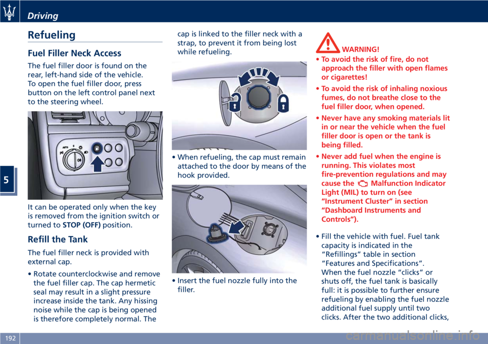
The fuel filler door is found on the
rear, left-hand side of the vehicle.
To open the fuel filler door, press
button on the left control panel next
to the steering wheel.
It can be operated only when the key
is removed from the ignition switch or
turned toSTOP (OFF)position.
Refill the Tank
The fuel filler neck is provided with
external cap.
• Rotate counterclockwise and remove
the fuel filler cap. The cap hermetic
seal may result in a slight pressure
increase inside the tank. Any hissing
noise while the cap is being opened
is therefore completely normal. Thecap is linked to the filler neck with a
strap, to prevent it from being lost
while refueling.
• When refueling, the cap must remain
attached to the door by means of the
hook provided.
• Insert the fuel nozzle fully into the
filler.
WARNING!
•To avoid the risk of fire, do not
approach the filler with open flames
or cigarettes!
•To avoid the risk of inhaling noxious
fumes, do not breathe close to the
fuel filler door, when opened.
•Never have any smoking materials lit
in or near the vehicle when the fuel
filler door is open or the tank is
being filled.
•Never add fuel when the engine is
running. This violates most
fire-prevention regulations and may
cause the
Malfunction Indicator
Light (MIL) to turn on (see
“Instrument Cluster” in section
“Dashboard Instruments and
Controls”).
• Fill the vehicle with fuel. Fuel tank
capacity is indicated in the
“Refillings” table in section
“Features and Specifications”.
When the fuel nozzle “clicks” or
shuts off, the fuel tank is basically
full: it is possible to further ensure
refueling by enabling the fuel nozzle
additional fuel supply until two
clicks. After the two additional clicks,
Driving
5
192
Page 197 of 286
the amount of fuel allowed by the
system is very low, we recommend
therefore not to persist further.
• Wait approximately 10 seconds
before removing the fuel nozzle in
order to ensure completed supply of
residual fuel and restrict the risk of
fouling the fuel filler door area.
• Remove the fuel nozzle.
• Insert the cap on the fuel filler neck.
• Tighten the cap, turning it clockwise
until it stops.
• Close the fuel tank door.
CAUTION!
To avoid fuel spillage and overfilling,
do not “top off” the fuel tank after
filling.
Emergency Fuel Filler Door
Release
If you are unable to unlock the fuel
filler door using the dedicated button,
use the fuel filler door emergency
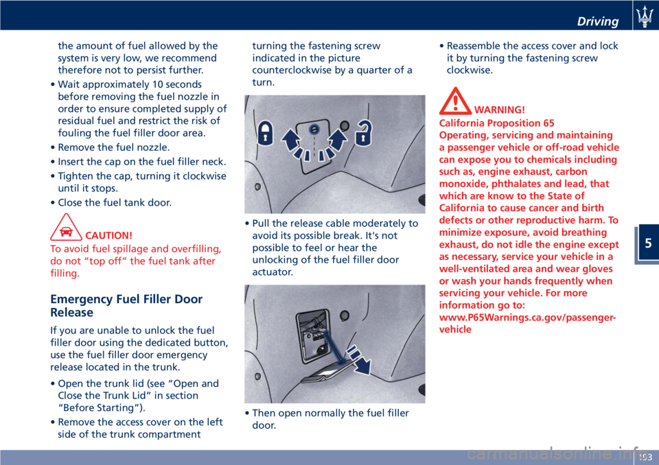
release located in the trunk.
• Open the trunk lid (see “Open and
Close the Trunk Lid” in section
“Before Starting”).
• Remove the access cover on the left
side of the trunk compartmentturning the fastening screw
indicated in the picture
counterclockwise by a quarter of a
turn.
• Pull the release cable moderately to
avoid its possible break. It's not
possible to feel or hear the
unlocking of the fuel filler door
actuator.
• Then open normally the fuel filler
door.• Reassemble the access cover and lock
it by turning the fastening screw
clockwise.
WARNING!
California Proposition 65
Operating, servicing and maintaining
a passenger vehicle or off-road vehicle
can expose you to chemicals including
such as, engine exhaust, carbon
monoxide, phthalates and lead, that
which are know to the State of
California to cause cancer and birth
defects or other reproductive harm. To
minimize exposure, avoid breathing
exhaust, do not idle the engine except
as necessary, service your vehicle in a
well-ventilated area and wear gloves
or wash your hands frequently when
servicing your vehicle. For more
information go to:
www.P65Warnings.ca.gov/passenger-
vehicle
Driving
5
193
Page 218 of 286
Auxiliary Jump-Start
Procedure
If your vehicle has a discharged battery
it can be jump-started using a set of
jumper cables and a battery of another
vehicle or by using a portable battery
booster. It is necessary to have proper
jumper cables in order to connect the
booster battery to the remote posts of
the discharged battery. Booster cables
have usually positive and negative
terminal clamps and are identified by a
different sheath color (red = positive,
black = negative). Maserati provides
on request jumper cables created for
its models and content in a practical
case.
NOTE:
TheAuthorized Maserati Dealercan
provide you with information about
the “Maserati Jumper Cables Kit”,
available in the “Genuine Accessories”
range.
Jump-starting can be dangerous if
done improperly so please follow the
procedures in this section carefully.NOTE:
When using a portable battery booster
pack, follow the battery
manufacturer’s operating instructions
and precautions.
CAUTION!
• To jump start a vehicle do not use a
portable battery, a booster pack or
any other booster source with a
system voltage greater than 14 Volts
or damage to the battery, starter
motor, alternator or electrical system
of the vehicle with the discharged
battery may occur.
• Do not use a battery charger for
emergency starting under any
circumstances. You could damage the
electronic systems, particularly the
control units managing the ignition
and fuel supply functions.
• If the battery is completely
discharged when the windows are
fully raised, open the door with the
utmost care; do not close the door
again until it is possible to lower the
window.
WARNING!
•Using booster packs that have not
been checked, which could therefore
release a too high charging voltage
(higher than 14 V), in extreme
environmental conditions (for
example: closed areas or without
proper ventilation and temperatures
higher than 122°F/50°C or lower
than -4°F/-20°C) create the right
conditions for ignition which could
then cause the battery to explode.
Therefore you shall always perform
jump-starting operations using the
adequate tools and in the best
environmental conditions, taking all
necessary precautions.
•Do not attempt jump-starting if the
discharged battery is frozen. It could
rupture or explode during jump start
and cause personal injury.
•Do not carry out this procedure if
you have not done it before:
incorrect maneuvers can originate
high electrical discharges and even
cause the battery to explode.
•To avoid the risk of explosion or fire,
do not approach the battery with
In an Emergency
6
214
Page 222 of 286
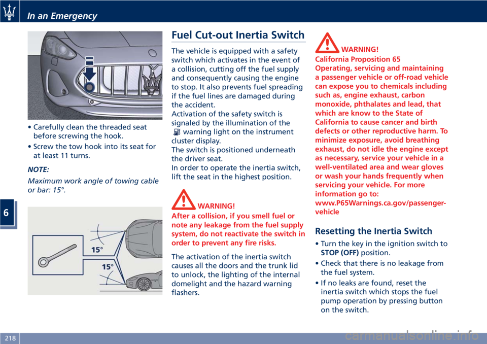
• Carefully clean the threaded seat
before screwing the hook.
• Screw the tow hook into its seat for
at least 11 turns.
NOTE:
Maximum work angle of towing cable
or bar: 15°.
Fuel Cut-out Inertia Switch
The vehicle is equipped with a safety
switch which activates in the event of
a collision, cutting off the fuel supply
and consequently causing the engine
to stop. It also prevents fuel spreading
if the fuel lines are damaged during
the accident.
Activation of the safety switch is
signaled by the illumination of the
warning light on the instrument
cluster display.
The switch is positioned underneath
the driver seat.
In order to operate the inertia switch,
lift the seat in the highest position.
WARNING!
After a collision, if you smell fuel or
note any leakage from the fuel supply
system, do not reactivate the switch in
order to prevent any fire risks.
The activation of the inertia switch
causes all the doors and the trunk lid
to unlock, the lighting of the internal
domelight and the hazard warning
flashers.
WARNING!
California Proposition 65
Operating, servicing and maintaining
a passenger vehicle or off-road vehicle
can expose you to chemicals including
such as, engine exhaust, carbon
monoxide, phthalates and lead, that
which are know to the State of
California to cause cancer and birth
defects or other reproductive harm. To
minimize exposure, avoid breathing
exhaust, do not idle the engine except
as necessary, service your vehicle in a
well-ventilated area and wear gloves
or wash your hands frequently when
servicing your vehicle. For more
information go to:
www.P65Warnings.ca.gov/passenger-
vehicle
Resetting the Inertia Switch
• Turn the key in the ignition switch to
STOP (OFF)position.
• Check that there is no leakage from
the fuel system.
• If no leaks are found, reset the
inertia switch which stops the fuel
pump operation by pressing button
on the switch.
In an Emergency
6
218
Page 230 of 286
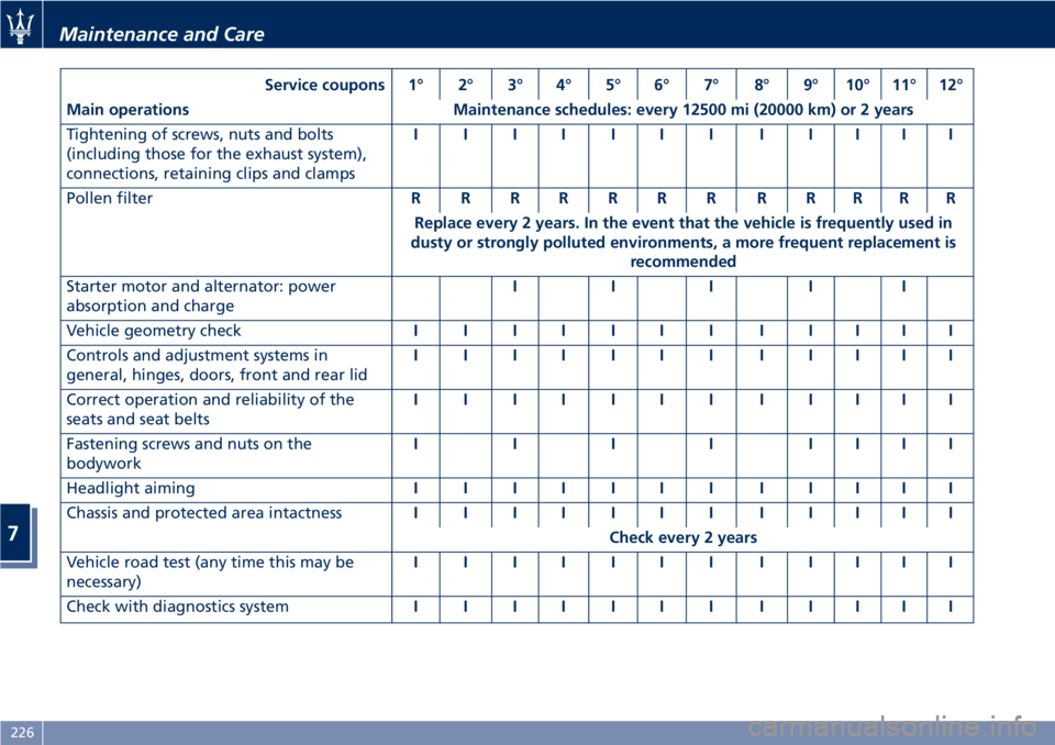
Service coupons 1° 2° 3° 4° 5° 6° 7° 8° 9° 10° 11° 12°
Main operations Maintenance schedules: every 12500 mi (20000 km) or 2 years
Tightening of screws, nuts and bolts
(including those for the exhaust system),
connections, retaining clips and clampsIIIIIIIIIIII
Pollen filterRRRRRRRRRRRR
Replace every 2 years. In the event that the vehicle is frequently used in
dusty or strongly polluted environments, a more frequent replacement is
recommended
Starter motor and alternator: power
absorption and chargeIII II
Vehicle geometry checkIIIIIIIIIIII
Controls and adjustment systems in
general, hinges, doors, front and rear lidIIIIIIIIIIII
Correct operation and reliability of the
seats and seat beltsIIIIIIIIIIII
Fastening screws and nuts on the
bodyworkIIIIIIII
Headlight aimingIIIIIIIIIIII
Chassis and protected area intactnessIIIIIIIIIIII
Check every 2 years
Vehicle road test (any time this may be
necessary)IIIIIIIIIIII
Check with diagnostics systemIIIIIIIIIIII
Maintenance and Care
7
226