sensor MASERATI GRANTURISMO CONVERTIBLE 2019 Owner's Manual
[x] Cancel search | Manufacturer: MASERATI, Model Year: 2019, Model line: GRANTURISMO CONVERTIBLE, Model: MASERATI GRANTURISMO CONVERTIBLE 2019Pages: 296, PDF Size: 9.01 MB
Page 155 of 296
Air Conditioning Controls
The vehicle is equipped with an
automatic dual-zone air conditioning
system that allows to adjust separately
the air temperature and the airflow
distribution in the left and in the right
zone of the passenger compartment,
according to the requests of the driver
and the front passenger.
A humidity sensor, positioned on the
inner surface of the windshield, over
the rearview mirror, allows the A/C
system to prevent/ eliminate fogging
of the windshield and side windows.
The best efficacy in preventing
fogging is obtained by selecting the
AUTO function, described later.
A dual zone solar sensor, positioned
on the center of the dashboard upper
surface, helps to achieve the best
comfort in presence of solar radiation.
CAUTION!
To ensure proper functioning of the
solar sensor, do not apply adhesive
parking stickers, etc. in the checking
area between the sensor and the
windshield. Therefore, keep the
windshield and the sensor clean to prevent accumulation of dust or other
impurities.
Dashboard Instruments and Controls
4
151
Page 181 of 296
engage the parking brake, but also to
shift the transmission shift lever to P
(Park) before leaving the vehicle.
When parking on hill roads, it is
important
to turn the front wheels
toward the curb on a downhill grade
and away from the curb on an uphill
grade.
Apply the parking brake before
placing the shift lever in P (Park),
otherwise the load on the
transmission locking mechanism may
make it difficult to move the shift
lever out of P (Park).
In certain conditions, it is however
advisable to disengage the parking
brake manually and slightly apply the
service brake for starting off. This is
advisable when there are obstacles
very close to the vehicle in the
direction in which you intend to move.
Brake and Stability
Control System
The vehicle is equipped with an
Electronic Stability Control (ESC)
anti-yawing system, which helps to
maintain directional control in the
event of loss of grip of the tires. The
system is able to detect potentially
dangerous situations for the stability
of the vehicle and automatically sets
the brakes on all four wheels in a
differentiated manner, in order to
provide a torque settlement of the
vehicle.
ESC includes the following subsystems:
• ASR (Anti-Slip Regulation)
• ABS (Anti-lock Braking System)
• EBD (Electronic Brake-force Distribution)
• HBA (Hydraulic Brake Assistance)
• BOS (Brake Override System)
WARNING!
• These systems cannot prevent the
natural laws of physics from
affecting the vehicle, nor can they
increase traction, braking or steering
efficiency beyond that afforded by
the condition of the vehicle brakes
and tires. •
These systems cannot prevent
collisions, including those resulting
from excessive speed in turns,
following another vehicle too
closely, or hydroplaning.
• The capabilities of a vehicle
equipped with these systems must
never be exploited in a reckless or
dangerous manner that could
jeopardize the driver’s and the
passenger’s safety or the safety of
others.
Electronic Stability Control
(ESC)
This system enhances directional
control and stability of the vehicle
under various driving conditions. The
ESC corrects over steering and under
steering of the vehicle by applying the
brake to the appropriate wheel.
Engine power may also be reduced to
assist in counteracting the conditions
of instability and maintain the right
direction. The system is also able to
reduce the engine power.
Through sensors fitted on the vehicle,
the ESC system detects the driver’s
chosen direction comparing it to the
one maintained while running. In case
of discrepancy between the required
trajectory and the current one, the
Driving
5
177
Page 183 of 296
• in the event of loss of grip on wetroads (aquaplaning).
The ASR system works in combination
with the electronic suspension control
system: in normal conditions (SPORT
mode off), stability in low and
medium grip conditions has priority,
while with SPORT mode active, the
system favors traction, thereby
optimizing vehicle performance on dry
asphalt.
The ASR system is automatically
activated every time the engine is
started and can be deactivated by
pressing
(ESC Off) button (see
"Drive Mode" in this section).
ASR System Failure
In the event of a fault, the system is
automatically disabled and cannot be
re-activated. While driving, this
condition is signaled by the
amber
warning light on the instrument
cluster display, which illuminates
together with the message “ASR
unavailable go to dealer”. Also the
(ESC On) amber warning light
illuminates inside the tachometer with
the message indicating that the ESC
system is unavailable. In this case drive
with the greatest care and have the
system immediately checked by the
nearest Authorized Maserati Dealer .MSR Function
The ASR system also controls the
engine braking torque when the
accelerator pedal is released under
low grip conditions (e.g., snow, ice,
etc.): in these conditions, the high
braking torque provided by the
engine may cause instability of the
vehicle.
The system, using the same sensors as
the ABS, detects skidding of one or
both driving wheels when the
accelerator is released and opens the
motor-driven throttle of the engine
fuel system thereby reducing the
braking torque and re-establishing the
maximum grip conditions for the
driving wheels.
WARNING!
The maximum deceleration that can
be obtained with the engine brake
always depends on the tire grip on
the road surface. Snow or ice
obviously reduce grip values.
WARNING!
California Proposition 65
Operating, servicing and maintaining
a passenger vehicle or off-road vehicle can expose you to chemicals including
such as, engine exhaust, carbon
monoxide, phthalates and lead, that
which are know to the State of
California to cause cancer and birth
defects or other reproductive harm. To
minimize exposure, avoid breathing
exhaust, do not idle the engine except
as necessary, service your vehicle in a
well-ventilated area and wear gloves
or wash your hands frequently when
servicing your vehicle. For more
information go to:
www.P65Warnings.ca.gov/passenger-
vehicle
Anti-Lock Braking System (ABS)
and Electronic Brake-force
Distribution (EBD)
The Anti-Lock Brake System (ABS)
provides increased vehicle stability and
brake performance under most
braking conditions. The system
automatically “pumps” the brakes
during severe braking to prevent
wheel lock-up.
The Electronic Brake-force Distribution
(EBD) prevents the rear wheels from
over-braking and provides greater
control of available braking forces
applied to the rear axle.
Driving
5
179
Page 195 of 296
WARNING!
• Improperly inflated tires can be
dangerous.
• Under-inflation increases tire flexing
and can result in tire overheating.
• Over-inflation reduces a tire's ability
to cushion shock. Objects on the
road and potholes can cause
damage that results in tire failure.
• Over-inflated or under-inflated tires
can affect vehicle handling and can
fail suddenly, resulting in loss of
vehicle control.
• Unequal tire pressures can cause
steering problems.
• Unequal tire pressures from one side
of the vehicle to the other can cause
the vehicle to drift to the right or
left.
• Always drive with each tire inflated
to the recommended cold tire
inflation pressure.
Economy
Improper
inflation pressures may
cause uneven wear patterns to
develop across the tire tread. These
abnormal wear patterns will reduce
tread life resulting in a need for
earlier tire replacement. Under- inflation also increases tire rolling
resistance resulting in higher fuel
consumption.
Ride comfort and vehicle stability
Proper tire inflation contributes to a
comfortable ride. Over-inflation
produces a jarring and uncomfortable
ride.
Tire Pressure Checkup
The proper cold tire inflation pressure
is indicated on the driver's side rear
door pillar and on the table “Tire
Inflation Pressure” in section
“Features and Specifications”.
Inflation pressure specified on the
table always refers to “cold tire
inflation pressure”. Cold tire inflation
pressure is defined as the tire pressure
after the vehicle has not been driven
for at least three hours, or driven less
than 1 mi (1,6 km) after a three hour
period.
Check tire pressures more often in
case of significant outside
temperature changes, as tire pressure
varies according to temperature
changes.
The pressure should be checked and if
necessary adjusted; tire wear and
overall conditions should also be
checked monthly. Tire pressures
change by approximately 1 PSI (0,07
bar) per 12°F (7°C) of air temperature
change. Keep this in mind when
checking tire pressure inside a garage,
especially in winter.
Example: If garage temperature = 68°F
(20°C) and the outside temperature =
32°F (0°C) then the cold tire inflation
pressure should be increased by 3 PSI
(0,21 bar) for every 12°F (7°C) for this
outside temperature condition.
Tire pressure may increase from 2 to 6
PSI (0,13 to 0,4 bar) during operation.
DO NOT reduce this normal pressure
build-up or your tire pressure will be
too low. After inspecting or adjusting
the tire pressure, always reinstall the
valve stem cap. This will prevent
moisture and dirt from entering the
valve stem, which could damage the
valve stem and the TPMS sensor
connected to it.
Tread Wear Indicators
Tread wear indicators are in the
original equipment tires to help you
determine when your tires should be
replaced.
These indicators are molded into the
bottom of the tread grooves.
When the tread is worn to one of the
tread wear indicators, the tire should
be replaced.
Driving
5
191
Page 196 of 296
WARNING!
The wet performance (aquaplaning
resistance) will decrease
proportionally to the thickness of the
tread.
Tires Durability
The service life of a tire depends on
various factors including, but not
limited to:
• driving style;
• tire pressure;
• distance driven.
WARNING!
Tires and the spare tire (if equipped)
should be replaced after six years,
regardless of the remaining tread.
Failure to follow this warning could
result in tire failure.
Replacement Tires
NOTE:
In order to maintain high performance
and safety level under all driving
conditions, Maserati strongly
recommends to use tires equivalent to
the originals in size, quality and
performance when replacement is
needed.
For the size designation of your tire
see the label on the driver's side rear
door pillar or see table “Wheels” in
section “Features and Specifications”.
The “Load Index” and “Speed Symbol”
for your tire will be found on the
original equipment tire sidewall.
It is recommended to replace the two
front tires or two rear tires as a pair.
Replacing just one tire can seriously
affect your vehicle’s handling.
If you ever replace a wheel assembly,
make sure that the wheel’s
specifications (valve, TPMS sensor and
tire) match those of the original
wheels. Failure to use equivalent
replacement tires may adversely affect
the safety, handling, and ride of your
vehicle.
Your Authorized Maserati Dealer is
available to provide suggestions as to the types of tires most suited to the
use foreseen by the Customer.
WARNING!
• Do not use a tire, wheel size or
rating other than that specified for
your vehicle. Some combinations of
unapproved tires and wheels may
change suspension dimensions and
performance characteristics,
resulting in altered steering,
handling, and braking operations of
the vehicle. This can cause
unpredictable handling and stress to
steering and suspension
components. Use only the tire and
wheel sizes with load ratings
appointed for your vehicle.
• Never use a tire with a smaller load
index or capacity, other than what
was originally equipped on your
vehicle. Using a tire with a smaller
load index could result in tire
overloading and failure.
• Always check the maximum speed
rating on the tire sidewall on any
tire on the vehicle.
Driving
5
192
Page 199 of 296
that prevent the TPMS from
functioning properly. Always check the
TPMS malfunction telltale after
replacing one or more tires or wheels
on your vehicle to ensure that the
replacement or alternate tires and
wheels allow the TPMS to continue to
function properly.
General Information
The Tire Pressure Monitoring System
(TPMS) will warn the driver of a low
tire pressure according to the vehicle
recommended cold pressure indicated
on the table “Tire Inflation Pressure”
in section “Features and
Specifications” and on the label
applied on the driver's side at the base
of the rear door pillar.
The cold tire inflation pressure must
not exceed the maximum inflation
pressure molded into the tire sidewall.
Check “Tires – General Information” in
section “Driving” for information on
how to properly inflate the tires.
The tire pressure will also increase as
the vehicle is driven - this is normal
and there is no adjustment required
when this occurs.
The TPMS will warn the driver of a low
tire pressure if the tire pressure falls
below the low-pressure warning limit
for any reason, including lowtemperature effects and natural
pressure loss of the tire.
The TPMS will continue to warn the
driver of low tire pressure as long as
the condition persists and will not turn
off until the tire pressure is equal or
above the recommended cold
inflation pressure.
The TPMS monitors the tire pressure
by means of special sensors fitted
inside the wheel rims, in position with
the inflation valve.
These sensors transmit a signal that is
detected by the antenna integrated in
the ECU.
The ECU processes this information
and, via the CAN line, transmits a
series of tire pressure data and system
errors, if any, to the instrument cluster.
The display may show the information
received by means of specific screen
pages, which can be recalled by
pressing briefly the "MODE" button
(see "TFT Display: Controls" in chapter
"Instrument Cluster" of the section
Dashboard Instruments and
Controls").
WARNING!
The TPMS warns the driver that the
tire pressure has decreased. This
warning does not exempt the driver
from periodically checking the tires
and from complying with the
prescribed tire pressure levels.
CAUTION!
• The TPMS has been optimized for the original equipment tires and
wheels. TPMS pressures and warning
have been established for the tire
size equipped on your vehicle.
Undesirable system operation or
sensor damage may occur when
using replacement equipment that is
not of the same size, type, and/or
(Continued)
Driving
5
195
Page 200 of 296
(Continued)
style. Aftermarket wheels can cause
sensor damage. Do not use
aftermarket tire sealants or balance
beads, as damage to the sensors may
result.
• The system can temporarily experience radio-electric interference
emitted by devices using similar
frequencies.
• After inspecting or adjusting the tire pressure, always reinstall the valve
stem cap. This will prevent moisture
and dirt from entering the valve
stem and damage the TPMS internal
sensor.
NOTE:
• Driving
on a significantly
underinflated tire causes the tire to
overheat and may lead to tire failure.
Under-inflation also reduces fuel
efficiency and tire tread life, and may
affect the vehicle’s handling and
stopping ability.
• The TPMS is not a substitute for
proper tire maintenance, and it is the
driver’s responsibility to maintain
correct tire pressure using an
accurate tire pressure gage, even if
under-inflation has not reached the level to trigger illumination of the
TPMS light
.
• Seasonal temperature changes will
affect tire pressure, and the TPMS
will monitor the actual tire pressure
in the tire.
Viewing Messages on the
Display
By pressing repeatedly the “MODE”
button of the control panel on left
side of the steering column, the user
can access the information page that
shows the pressure values of each tire
(“Tire Pressure” screen page: see
paragraph "TFT Display: Screen Pages"
in chapter "Instrument Cluster" of
section "Dashboard Instruments and
Controls").
If system faults or low pressure is
detected on a not indentified tire, "Check Tire Pressure" or "TPMS
Malfunction" pop-up message will be
displayed for 10 seconds. The
amber warning light will
permanently illuminate on the right
side of the instrument cluster display.
With a malfunction detected, the "Tire
Pressure" screen page will not be
available while will be available the
calibration screen page.
The “Tire Pressure” screen page
becomes available again, until the
malfunction is corrected.
Low Tire Pressure Conditions
The signal transmitted by the ECU
activates messages and symbols on the
TFT display with two priority levels
corresponding to the following
thresholds:
• Soft Warning: if the pressure is 10% lower than the rated pressure;
• Hard Warning: if the pressure is 17% lower than the rated pressure.
The system refers to the rated pressure
acquired after calibration.
The two alarm thresholds for
monitoring the tire pressure
respectively activate the following
alerts:
• “Check tire pressure” illuminates on the display when the pressure of one
Driving
5
196
Page 203 of 296
“--,--” will be displayed in the place of
the values.
NOTE:
•The system will not perform
calibration if the pressure is below 2
bar (29 psi).
• To allow the system to acquire the
sensors’s data, after the startup of
the car, if possible avoid to stop.
During this interval the TFT display
can show screen page with dashes
“--,--” in the place of the pressure
levels of each tire.
• If calibration is not completed within
10 minutes of driving the car, the
instrument cluster shows “TPMS
Malfunction” pop-up message and
“Tire Pressure” screen disappear. The
warning light remains light on.
TPMS Malfunction
Screen page shown in picture may
appear in the following cases:
• malfunction in the ECU
system/wiring;
• no signal reception by one or more sensors due to malfunctioning,
broken or dead battery;
• ECU malfunction. The display procedure follows the
usual logic of malfunctions. Therefore,
after 30 seconds, the display will show
the screen page that was active before
the malfunction occurred.
In addition to screen page being
displayed, the
amber warning
light, which is permanently
illuminated on the instrument cluster,
will flash for 85 seconds, after which it
will remain permanently on until the
situation is corrected. The information
page that shows the pressure value for
each tire cannot be recalled.
Fuel Requirements
The engines are designed to meet all
environmental regulations and
provide excellent fuel economy and
performance when using unleaded
premium gasoline with an AKI octane
rating of 91 or above. AKI (Anti Knock
Index) is an average on the Research
Octane Number, RON, and the Motor
Octane Number, MON (RON + MON/2
gives you the AKI).
For vehicle top performance, use
unleaded premium gasoline with no
less than 93 minimum AKI octane
rating.
Poor quality gasoline can cause
problems such as hard starting,
stalling, and hesitations. If you
experience these symptoms, try
another brand of gasoline before
considering service for the vehicle at
an Authorized Maserati Dealer .
Besides using unleaded gasoline with
the proper octane rating, gasoline
that contain detergents, anti-corrosion
and stability additives are
recommended. Using gasoline that
have these additives may help improve
fuel economy, reduce emissions, and
maintain vehicle performance.
Driving
5
199
Page 212 of 296
emergency starting, only use an
auxiliary battery.
• While driving, if the engine does not run smoothly, you may continue
driving but reducing engine
performance to a minimum; you
should then contact the Authorized
Maserati Dealer as soon as possible.
• Never run the engine, even if only for testing, with one or more spark
plugs disconnected.
• Do not warm up the engine letting it idle before starting off, except in the
event that the external temperature
is very low and, even then, for no
longer than 30 seconds.
Catalytic Converter Warnings
During normal operation the catalytic
converter produces high temperatures.
Failure to comply with following rules
can create fire hazards.
• Do not park the vehicle onflammable materials (e.g. grass, dry
leaves, pine needles, etc.).
• Do not install heat guards and do not remove those already fitted to
the catalytic converter and to the
exhaust manifold.
• Do not spray anything on the catalytic converter, Oxygen sensor
and exhaust manifold. In addition to the catalytic converter
system, the vehicles are equipped with
a system for controlling fuel vapor
emissions. This system, called ORVR,
has been designed to help reduce
atmospheric pollution by the
evaporation from the fuel system
during the refueling process. Also,
specific to these vehicles is the fuel
filler neck which comes equipped with
a sealed plug that is grounded to
avoid possible sparking during
re-fueling.
WARNING!
California Proposition 65
Operating, servicing and maintaining
a passenger vehicle or off-road vehicle
can expose you to chemicals including
such as, engine exhaust, carbon
monoxide, phthalates and lead, that
which are know to the State of
California to cause cancer and birth
defects or other reproductive harm. To
minimize exposure, avoid breathing
exhaust, do not idle the engine except
as necessary, service your vehicle in a
well-ventilated area and wear gloves
or wash your hands frequently when
servicing your vehicle. For more
information go to: www.P65Warnings.ca.gov/passenger-
vehicle
Other Tips
• Do not warm up the engine when
the vehicle is stationary: in these
conditions the engine heats up much
more slowly, thus increasing fuel
consumption and emissions. It is
advisable to move off slowly,
avoiding high engine rpm.
• As soon as traffic conditions and the route permit it, use a higher gear.
• Avoid depressing the accelerator repeatedly during stops at traffic
lights or before turning off the
engine.
• Keep your speed as regular as possible, avoiding unnecessary
braking and acceleration, which
cause fuel wastage and strongly
increase exhaust emissions.
• Turn the engine off if the vehicle remains stationary for a long time.
• Check the tire pressure regularly: if the pressure is too low, fuel
consumption increases and the tires
are damaged.
• Do not transport unnecessary heavy objects in the trunk compartment.
Driving
5
208
Page 238 of 296
Scheduled Service Plan
The Scheduled Maintenance services
listed in this chapter must be done
within the times or mileages specified
to protect your vehicle warranty and
ensure the best vehicle performance
and reliability.
More frequent maintenance may be
needed for vehicles in severeoperating conditions, such as dusty
areas and very short trip driving.
Inspection and service should also be
done anytime a malfunction is
suspected.
Maserati recommends that these
maintenance intervals be performed at
the
Authorized Maserati Dealer . Thetechnicians at your dealership know
your vehicle best, and have access to
factory-approved information,
genuine Maserati parts, and specially
designed electronic and mechanical
tools that can help prevent future
costly repairs.
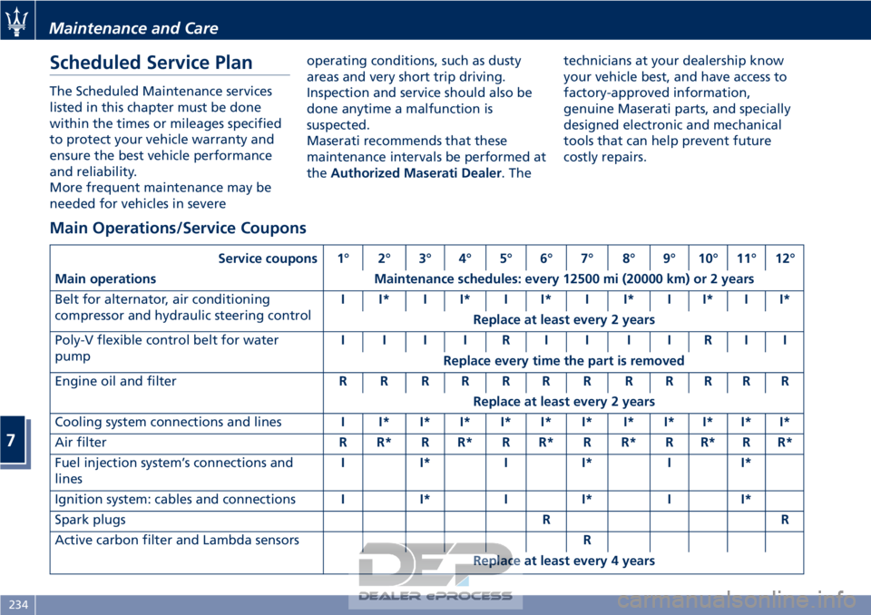
Main Operations/Service Coupons
Service coupons 1° 2° 3° 4° 5° 6° 7° 8° 9° 10° 11° 12°
Main operations Maintenance schedules: every 12500 mi (20000 km) or 2 years
Belt for alternator, air conditioning
compressor and hydraulic steering control I I* I I* I I* I I* I I* I I*
Replace at least every 2 years
Poly-V flexible control belt for water
pump IIIIRIIIIRII
Replace every time the part is removed
Engine oil and filter RRRRRRRRRRRR
Replace at least every 2 years
Cooling system connections and lines II*I*I*I*I*I*I*I*I*I*I*
Air filter R R* R R* R R* R R* R R* R R*
Fuel injection system’s connections and
lines I I* I I* I I*
Ignition system: cables and connections I I* I I* I I*
Spark plugs RR
Active carbon filter and Lambda sensors R
Replace at least every 4 years
Maintenance and Care
7
234