MASERATI GRANTURISMO CONVERTIBLE 2019 Repair Manual
Manufacturer: MASERATI, Model Year: 2019, Model line: GRANTURISMO CONVERTIBLE, Model: MASERATI GRANTURISMO CONVERTIBLE 2019Pages: 296, PDF Size: 9.01 MB
Page 61 of 296
Installing Child Restraint
Systems using the Vehicle Seat
Belt equipped with ALR All the passenger seat belts are
equipped with an Automatic Locking
Retractor (ALR) to secure child
protection through a Child Restraint
System (CRS). These types of seat belts
are designed to keep the lap portion
of the seat belt tight around the child
restraint seat avoiding to use a locking
clip.
The ALR will make a ratcheting noise
if the entire belt is pulled out of the
retractor in order to enable the belt to
retract subsequently. For additional
information on ALR, see “Using Seat
Belt in Automatic Locking Retractor
(ALR) Mode” in “Occupants Restraint
Systems” in this section.
To install a Child Restraint System with
ALR, pull enough of the belt out of
the retractor leading it through the
belt path of the protection device.
Slide the latch into the buckle until it
clicks, then remove the entire safety
belt from the retractor in order to
rewound. While rewinding a click will
indicate the safety belt is now in
Automatic Locking mode.
Exert then a traction on the exceeded
lap section of the belt in order to tighten it around the child restraint
seat. All seat belts will loosen over
time, it is therefore necessary to check
them periodically and set them
properly.
Lower Anchors and Tether for
Children (LATCH) Your vehicle's rear outboard seats are
all equipped with the child restraint
anchorage system called LATCH.
The LATCH system allows the child
restraint systems to be fixed without
using the vehicle's seat belts, instead
fixing the child restraint system to the
vehicle structure, using lower
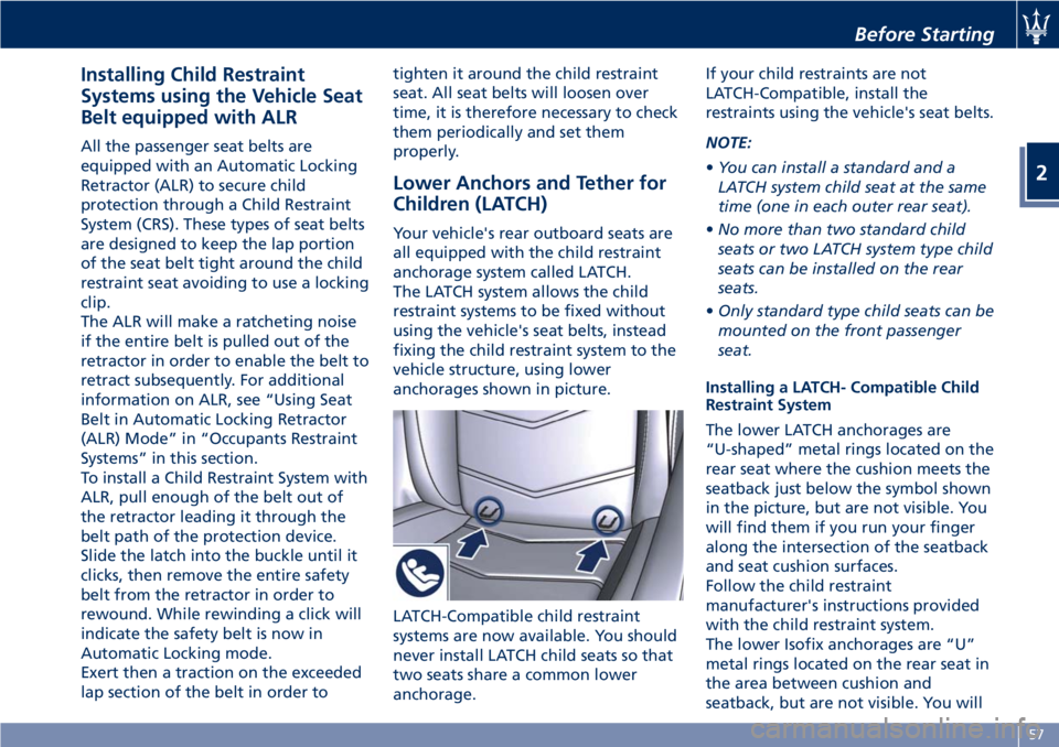
anchorages shown in picture.
LATCH-Compatible child restraint
systems are now available. You should
never install LATCH child seats so that
two seats share a common lower
anchorage. If your child restraints are not
LATCH-Compatible, install the
restraints using the vehicle's seat belts.
NOTE:
• You can install a standard and a
LATCH system child seat at the same
time (one in each outer rear seat).
• No more than two standard child
seats or two LATCH system type child
seats can be installed on the rear
seats.
• Only standard type child seats can be
mounted on the front passenger
seat.
Installing a LATCH- Compatible Child
Restraint System
The lower LATCH anchorages are
“U-shaped” metal rings located on the
rear seat where the cushion meets the
seatback just below the symbol shown
in the picture, but are not visible. You
will find them if you run your finger
along the intersection of the seatback
and seat cushion surfaces.
Follow the child restraint
manufacturer's instructions provided
with the child restraint system.
The lower Isofix anchorages are “U”
metal rings located on the rear seat in
the area between cushion and
seatback, but are not visible. You willBefore Starting
2
57
Page 62 of 296
easily feel them if you run your finger
along the intersection of the seatback
and seat cushion surfaces.
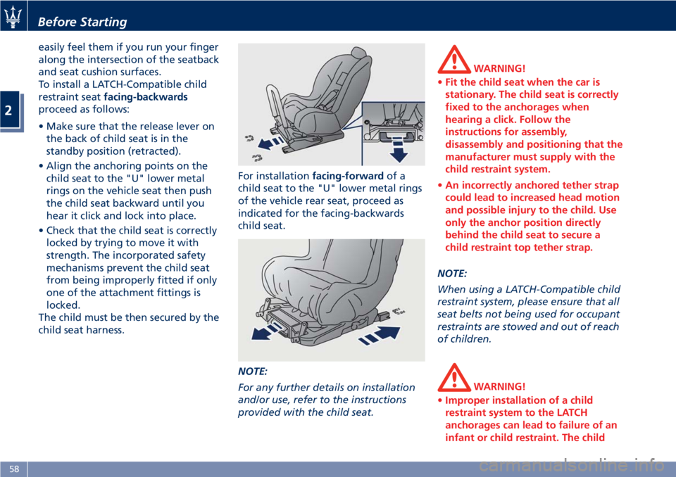
To install a LATCH-Compatible child
restraint seat facing-backwards
proceed as follows:
• Make sure that the release lever on
the back of child seat is in the
standby position (retracted).
• Align the anchoring points on the
child seat to the "U" lower metal
rings on the vehicle seat then push
the child seat backward until you
hear it click and lock into place.
• Check that the child seat is correctly
locked by trying to move it with
strength. The incorporated safety
mechanisms prevent the child seat
from being improperly fitted if only
one of the attachment fittings is
locked.
The child must be then secured by the
child seat harness. For installation facing-forward of a
child seat to the "U" lower metal rings
of the vehicle rear seat, proceed as
indicated for the facing-backwards
child seat.
NOTE:
For any further details on installation
and/or use, refer to the instructions
provided with the child seat. WARNING!
• Fit the child seat when the car is
stationary. The child seat is correctly
fixed to the anchorages when
hearing a click. Follow the
instructions for assembly,
disassembly and positioning that the
manufacturer must supply with the
child restraint system.
• An incorrectly anchored tether strap
could lead to increased head motion
and possible injury to the child. Use
only the anchor position directly
behind the child seat to secure a
child restraint top tether strap.
NOTE:
When
using a LATCH-Compatible child
restraint system, please ensure that all
seat belts not being used for occupant
restraints are stowed and out of reach
of children.
WARNING!
• Improper installation of a child
restraint system to the LATCH
anchorages can lead to failure of an
infant or child restraint. The childBefore Starting
2
58
Page 63 of 296
could be badly injured or killed.
Follow the child restraint
manufacturer's directions exactly
when installing an infant or child
restraint system.
• Child restraint anchorages are
designed to withstand only those
loads imposed by correctly fitted
child restraints. Under no
circumstances are they to be used
for adult seat belts, harnesses, or for
attaching other items or equipment
to the vehicle.
Important Safety Notice for
Transporting Children • Install the child seat on the rear seat
as this is the safest position in case of
collisions.
• Keep the instructions in the vehicle
together with the documents and
this owner’s manual. Do not use a
child restraint system which does not
contain instructions for use.
• Every child has to use one child
restraint system; never carry two
children using only one child seat.
• If using the vehicle seat belt, always
check that the belt does not restrain
the child's throat. • Firmly pull the seat belt to check
that it is correctly buckled.
• Never allow a child to seat
improperly or to unbuckle the seat
belt while driving.
• Never allow a child to wear the
shoulder portion of the belt under
the arms or behind the back.
• Never carry children on your lap, not
even newborns. No one can restrain
a child in the event of an accident.
• In case of accident, replace the child
seat with a new one. Transporting Pets Air bags deploying in the front seat
could harm your pet. An unrestrained
pet will be thrown about and possibly
injured, or injure a passenger during
panic braking or in an accident.
Pets should be restrained in the rear
seat in pet harnesses or pet carriers
that are secured by vehicle seat belts.Before Starting
2
59
Page 64 of 296
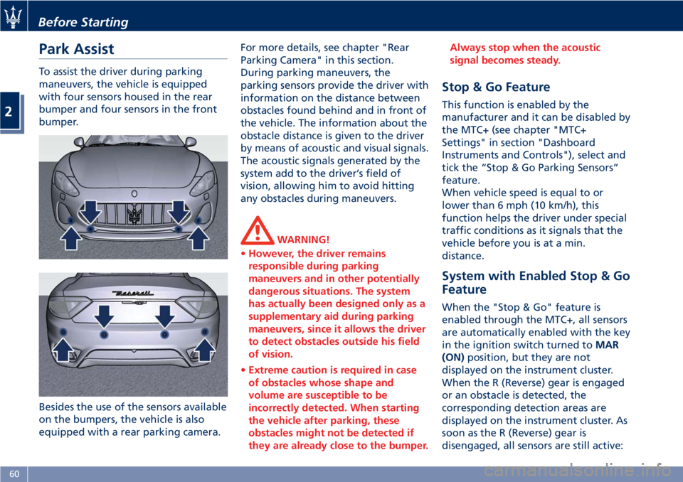
Park Assist To assist the driver during parking
maneuvers, the vehicle is equipped
with four sensors housed in the rear
bumper and four sensors in the front
bumper.
Besides the use of the sensors available
on the bumpers, the vehicle is also
equipped with a rear parking camera. For more details, see chapter "Rear
Parking Camera" in this section.
During parking maneuvers, the
parking sensors provide the driver with
information on the distance between
obstacles found behind and in front of
the vehicle. The information about the
obstacle distance is given to the driver
by means of acoustic and visual signals.
The acoustic signals generated by the
system add to the driver’s field of
vision, allowing him to avoid hitting
any obstacles during maneuvers.
WARNING!
• However, the driver remains
responsible during parking
maneuvers and in other potentially
dangerous situations. The system
has actually been designed only as a
supplementary aid during parking
maneuvers, since it allows the driver
to detect obstacles outside his field
of vision.
• Extreme caution is required in case
of obstacles whose shape and
volume are susceptible to be
incorrectly detected. When starting
the vehicle after parking, these
obstacles might not be detected if
they are already close to the bumper. Always stop when the acoustic
signal becomes steady.
Stop & Go Feature This function is enabled by the
manufacturer and it can be disabled by
the MTC+ (see chapter "MTC+
Settings" in section "Dashboard
Instruments and Controls"), select and
tick the “Stop & Go Parking Sensors”
feature.
When vehicle speed is equal to or
lower than 6 mph (10 km/h), this
function helps the driver under special
traffic conditions as it signals that the
vehicle before you is at a min.
distance.
System with Enabled Stop & Go
Feature When the "Stop & Go" feature is
enabled through the MTC+, all sensors
are automatically enabled with the key
in the ignition switch turned to MAR
(ON) position, but they are not
displayed on the instrument cluster.
When the R (Reverse) gear is engaged
or an obstacle is detected, the
corresponding detection areas are
displayed on the instrument cluster. As
soon as the R (Reverse) gear is
disengaged, all sensors are still active:Before Starting
2
60
Page 65 of 296
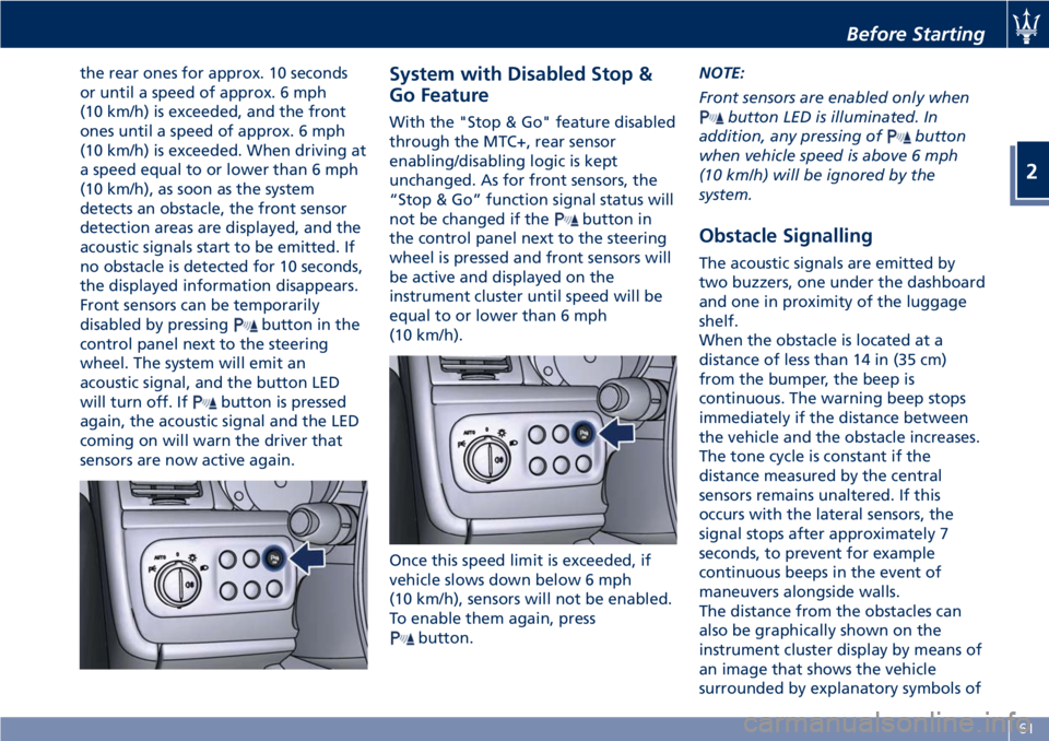
the rear ones for approx. 10 seconds
or until a speed of approx. 6 mph
(10 km/h) is exceeded, and the front
ones until a speed of approx. 6 mph
(10 km/h) is exceeded. When driving at
a speed equal to or lower than 6 mph
(10 km/h), as soon as the system
detects an obstacle, the front sensor
detection areas are displayed, and the
acoustic signals start to be emitted. If
no obstacle is detected for 10 seconds,
the displayed information disappears.
Front sensors can be temporarily
disabled by pressing
button in the
control panel next to the steering
wheel. The system will emit an
acoustic signal, and the button LED
will turn off. If
button is pressed
again, the acoustic signal and the LED
coming on will warn the driver that
sensors are now active again. System with Disabled Stop &
Go Feature With the "Stop & Go" feature disabled
through the MTC+, rear sensor
enabling/disabling logic is kept
unchanged. As for front sensors, the
“Stop & Go” function signal status will
not be changed if the
button in
the control panel next to the steering
wheel is pressed and front sensors will
be active and displayed on the
instrument cluster until speed will be
equal to or lower than 6 mph
(10 km/h).
Once this speed limit is exceeded, if
vehicle slows down below 6 mph
(10 km/h), sensors will not be enabled.
To enable them again, press
button. NOTE:
Front sensors are enabled only when
button LED is illuminated. In
addition, any pressing of
button
when vehicle speed is above 6 mph
(10 km/h) will be ignored by the
system.
Obstacle Signalling The acoustic signals are emitted by
two buzzers, one under the dashboard
and one in proximity of the luggage
shelf.
When the obstacle is located at a
distance of less than 14 in (35 cm)
from the bumper, the beep is
continuous. The warning beep stops
immediately if the distance between
the vehicle and the obstacle increases.
The tone cycle is constant if the
distance measured by the central
sensors remains unaltered. If this
occurs with the lateral sensors, the
signal stops after approximately 7
seconds, to prevent for example
continuous beeps in the event of
maneuvers alongside walls.
The distance from the obstacles can
also be graphically shown on the
instrument cluster display by means of
an image that shows the vehicle
surrounded by explanatory symbols ofBefore Starting
2
61
Page 66 of 296
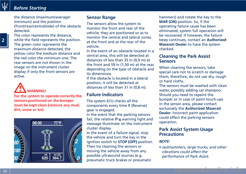
the distance (maximum/average/
minimum) and the position
(front/rear/central/side) of the obstacle
detected.
The color represents the distance,
while the field represents the position.
The green color represents the
maximum distance detected, the
yellow color the medium distance and
the red color the minimum one. The
rear sensors are not shown in the
image on the instrument cluster
display if only the front sensors are
active.
WARNING!
For the system to operate correctly the
sensors positioned on the bumper
must be kept clean (remove any mud,
dirt, snow or ice). Sensor Range The sensors allow the system to
monitor the front and rear of the
vehicle; they are positioned so as to
monitor the central and lateral zones
at the front and at the rear of the
vehicle.
In the event of an obstacle located in a
central area, this will be detected at
distances of less than 35 in (0,9 m) at
the front and 59 in (1,50 m) at the rear,
depending on the type of obstacle and
its dimensions.
If the obstacle is located in a lateral
position, it will be detected at
distances of less than 31 in (0,8 m).
Failure Indicators The system ECU checks all the
components every time R (Reverse)
gear is engaged.
In the event that the parking sensors
fail, the relative
warning light and
message illuminate on the instrument
cluster display.
In the event of a failure signal, stop
the vehicle and turn the key in the
ignition switch to STOP (OFF) position.
Then try cleaning the sensors or
moving the vehicle away from any
possible ultrasound sources (e.g.
pneumatic truck brakes or pneumatic hammers) and rotate the key to the
MAR (ON) position. So, if the
operating failure cause has been
eliminated, system full operation will
be recovered. If however, the failure
beep continues, contact an Authorized
Maserati Dealer to have the system
checked.
Cleaning the Park Assist
Sensors When cleaning the sensors, take
special care not to scratch or damage
them; therefore, do not use dry, rough
or hard cloths.
The sensors must be washed with clean
water, possibly adding car shampoo.
Should you need to repaint the
bumper or in case of paint touch-ups
in the sensor area, please contact
exclusively the Authorized Maserati
Dealer . Incorrect paint application
could affect the parking sensors
operation.
Park Assist System Usage
Precautions NOTE:
• Jackhammers, large trucks, and other
vibrations could affect the
performance of Park Assist.Before Starting
2
62
Page 67 of 296
• Objects such as bicycle carriers,
trailer hitches, etc., must not be
placed within 12 in (30 cm) from the
rear bumper while driving the
vehicle. Failure to do so can result in
the system misinterpreting a close
object as a sensor problem, causing
the service Park Assist message to be
displayed in the instrument cluster.
CAUTION!
• Park Assist is only a parking aid and
it is unable to recognize every
obstacle, including small obstacles.
Parking curbs might only be
temporarily detected or not
detected at all. Obstacles located
above or below the sensors will not
be detected when they are in close
proximity.
• The vehicle must be driven slowly
when using Park Assist in order to be
able to stop in time when an
obstacle is detected. When backing
up, it is recommended that the
driver looks over his/her shoulder
when using Park Assist. WARNING!
Drivers must be careful when backing
up even when using the Park Assist
system. Always check carefully behind
your vehicle, look behind you, and be
sure to check for pedestrians, animals,
other vehicles, obstructions, and blind
spots before backing up. You are
responsible for safety and must
continue to pay attention to your
surroundings. Failure to do so can
result in serious injury or death. Rear Parking Camera Your vehicle is equipped with a rear
parking camera that allows you to see
an image on the MTC+ screen of the
rear surroundings of your vehicle
whenever the shift lever is put into R
(Reverse).
When “Parkview Backup Camera
Delay” mode is enabled on MTC+, the
rear view image shall be displayed for
up to 10 seconds after shifting out of
R (Reverse).
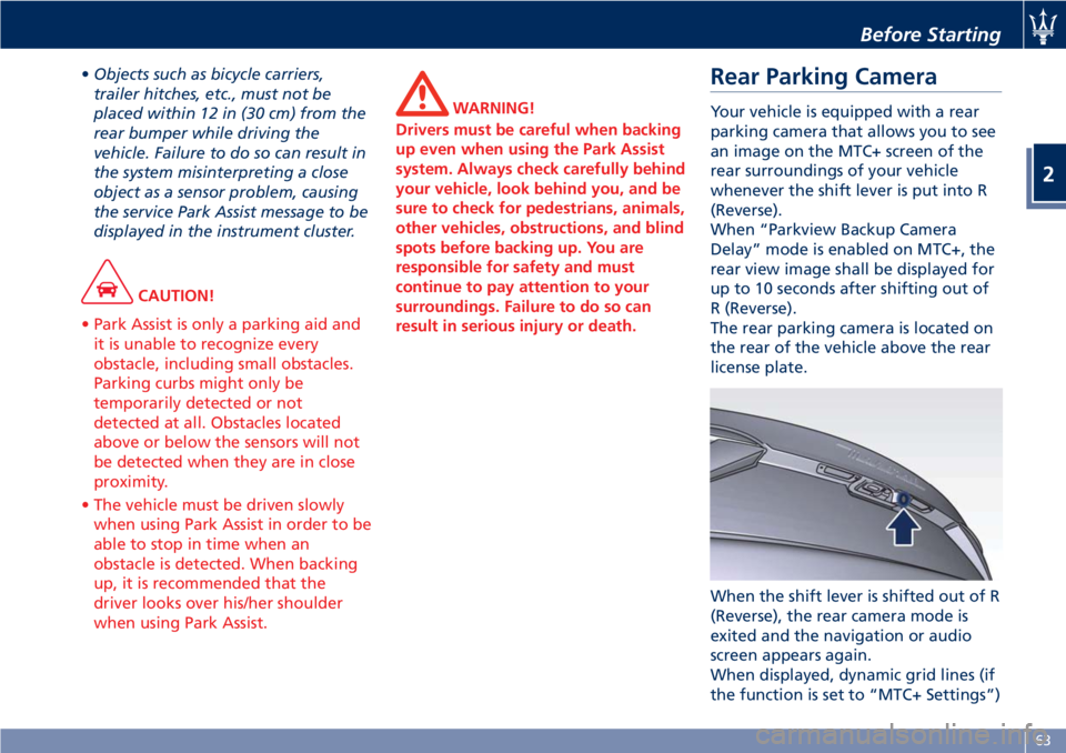
The rear parking camera is located on
the rear of the vehicle above the rear
license plate.
When the shift lever is shifted out of R
(Reverse), the rear camera mode is
exited and the navigation or audio
screen appears again.
When displayed, dynamic grid lines (if
the function is set to “MTC+ Settings”)Before Starting
2
63
Page 68 of 296
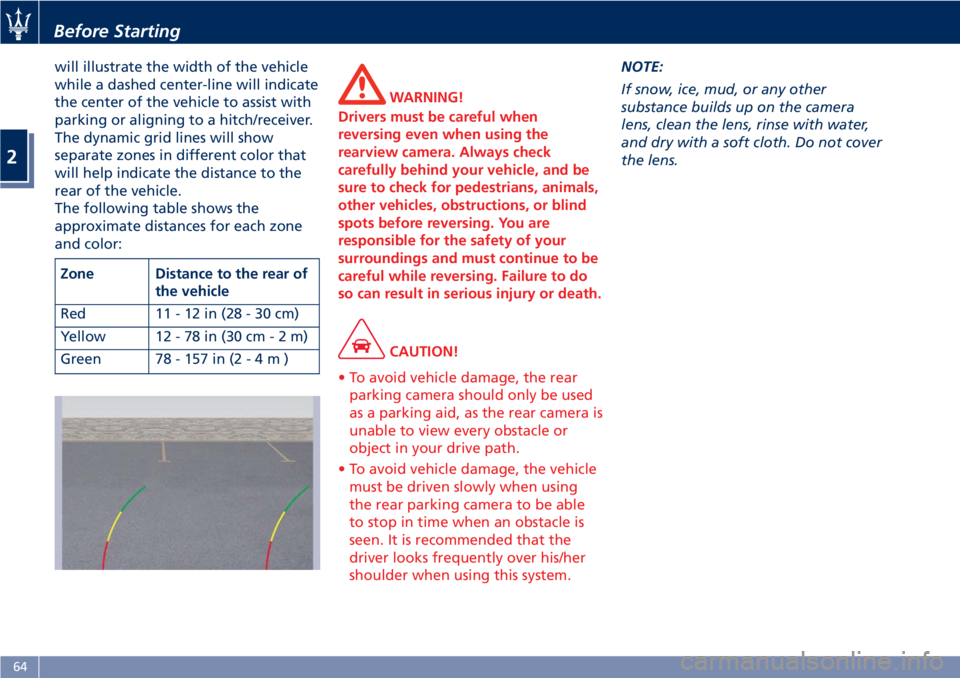
will illustrate the width of the vehicle
while a dashed center-line will indicate
the center of the vehicle to assist with
parking or aligning to a hitch/receiver.
The dynamic grid lines will show
separate zones in different color that
will help indicate the distance to the
rear of the vehicle.
The following table shows the
approximate distances for each zone
and color:
Zone Distance to the rear of
the vehicle
Red 11-12in(28-30cm)
Yellow 12 - 78 in (30 c m-2m)
Green 78 - 157 in ( 2-4m) WARNING!
Drivers must be careful when
reversing even when using the
rearview camera. Always check
carefully behind your vehicle, and be
sure to check for pedestrians, animals,
other vehicles, obstructions, or blind
spots before reversing. You are
responsible for the safety of your
surroundings and must continue to be
careful while reversing. Failure to do
so can result in serious injury or death.
CAUTION!
• To avoid vehicle damage, the rear
parking camera should only be used
as a parking aid, as the rear camera is
unable to view every obstacle or
object in your drive path.
• To avoid vehicle damage, the vehicle
must be driven slowly when using
the rear parking camera to be able
to stop in time when an obstacle is
seen. It is recommended that the
driver looks frequently over his/her
shoulder when using this system. NOTE:
If
snow, ice, mud, or any other
substance builds up on the camera
lens, clean the lens, rinse with water,
and dry with a soft cloth. Do not cover
the lens.Before Starting
2
64
Page 69 of 296
Safety Tips Transporting Passengers WARNING!
• Do not leave children or animals
inside parked vehicles in hot
weather. Interior heat build-up may
cause serious injury.
• Never ride in a cargo area, inside of
a vehicle.
• Do not allow people to ride in any
area of your vehicle that is not
equipped with seats and seat belts.
• Be sure everyone in your vehicle is
in a seat and using a seat belt
properly. Exhaust Gas WARNING!
Exhaust gases can injure. They contain
carbon monoxide (CO), which is
colorless and odorless. Breathing it
can make you unconscious and can
eventually poison you. To avoid
breathing (CO), follow these safety
tips:
• Do not run the engine in a closed
garage or in confined areas any
longer than needed to move your
vehicle in or out of the area.
• If it is necessary to sit in a parked
vehicle with the engine running,
adjust your heating or cooling
controls to force outside air into the
vehicle. Set the blower at high
speed.
• If you are required to drive with the
trunk lid open, make sure that all
windows are closed and the climate
control blowers switch is set at high
speed. DO NOT use the recirculation
mode.
The best protection against carbon
monoxide
entry into the passenger
compartment is a properly maintained
engine exhaust system. Whenever detecting a change in the
sound of the exhaust system or
eventual exhaust fumes inside the
vehicle have the Authorized Maserati
Dealer inspect the complete exhaust
system and adjacent body areas for
broken, damaged, deteriorated, or
mispositioned parts.
Open seams or loose connections
could permit exhaust fumes to seep
into the passenger compartment.
WARNING!
California Proposition 65
Operating, servicing and maintaining
a passenger vehicle or off-road vehicle
can expose you to chemicals including
such as, engine exhaust, carbon
monoxide, phthalates and lead, that
which are know to the State of
California to cause cancer and birth
defects or other reproductive harm. To
minimize exposure, avoid breathing
exhaust, do not idle the engine except
as necessary, service your vehicle in a
well-ventilated area and wear gloves
or wash your hands frequently when
servicing your vehicle. For more
information go to:
www.P65Warnings.ca.gov/passenger-
vehicleBefore Starting
2
65
Page 70 of 296
Vehicle Safety Checks Seat Belts
• Inspect the belt system periodically,
checking for cuts, frays, and loose
parts. Damaged parts must be
replaced immediately.
• Do not disassemble or modify the
system.
• If the belt has been sharply pulled,
for example as the result of an
accident, the safety belt, together
with the anchoring devices, the
anchoring device mounting screws
and the pretensioner must be
completely replaced. Even if the belt
does not present any exterior signs
of wear or damage, it may have lost
its restraining properties.
Air bag Warning Light
The
warning light should illuminate
and remain lit for a few seconds bulb
checking when the key in the ignition
switch is turned in MAR (ON) position
(see “Supplemental Restraint System
(SRS) — Air bags” chapter in this
section).
•Ifthe
warning light does not
illuminate while starting, contact an
Authorized Maserati Dealer . •Ifthe
warning light stays on,
flickers, or comes on while driving,
have the system checked by an
Authorized Maserati Dealer .
Defroster
Check operation by selecting the
defrost mode and place the fan system
on high speed (see “Air Conditioning
Controls” chapter in section
“Dashboard Instruments and
Controls”).
You should be able to feel the air
directed against the windshield and
front side windows. Contact an
Authorized Maserati Dealer for service
if your defroster is inoperable.
Floor Mat
Always use floor mats designed to fit
the footwell of your vehicle. Use only
floor mats that leave the pedal area
unobstructed and that are firmly
secured so that they cannot slip out of
position and interfere with the pedals
or impair safe operation of your
vehicle.
NOTE:
The Authorized Maserati Dealer can
provide you with any information
about the available Maserati floor
mats included in the “Genuine
Accessories” range. WARNING!
Pedals that cannot move freely can
cause loss of vehicle control and
increase the risk of serious personal
injury.
• Always make sure that floor mats
are properly attached to the proper
fasteners.
• Never place or install floor mats or
other floor coverings in the vehicle
that cannot be properly secured to
prevent them from moving and
interfering with the pedals.
• Never put floor mats or other floor
coverings on top of already installed
floor mats. Additional floor mats and
other coverings will reduce the size
of the pedal area and interfere with
the pedals.
• Check mounting of mats on a regular
basis. Always properly reinstall and
secure floor mats that have been
removed for cleaning.
• Always make sure that objects
cannot fall into the driver footwell
while the vehicle is moving. Objects
can become trapped under the brake
pedal and accelerator pedal causing
a loss of vehicle control.Before Starting
2
66