start stop button MASERATI LEVANTE 2019 User Guide
[x] Cancel search | Manufacturer: MASERATI, Model Year: 2019, Model line: LEVANTE, Model: MASERATI LEVANTE 2019Pages: 436, PDF Size: 15.24 MB
Page 59 of 436
tailpipes as they can reach high
temperatures and, in case of contact,
they can cause severe burns.
• When it is not necessary to open the
power liftgate with the Hands free
mode, make sure the key fob is
outside the range of use (3.3 ft/1 m).
Otherwise, the power liftgate can
be opened accidentally by an
unintentional movement of the
foot.
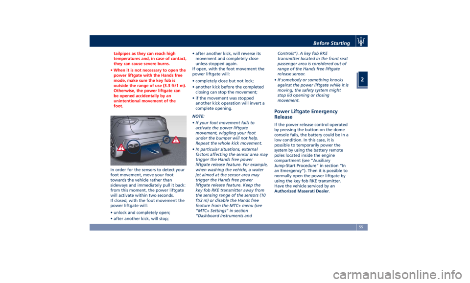
In order for the sensors to detect your
foot
movement, move your foot
towards the vehicle rather than
sideways and immediately pull it back:
from this moment, the power liftgate
will activate within two seconds.
If closed, with the foot movement the
power liftgate will:
• unlock and completely open;
• after another kick, will stop; • after another kick, will reverse its
movement and completely close
unless stopped again.
If open, with the foot movement the
power liftgate will:
• completely close but not lock;
• another kick before the completed
closing can stop the movement;
• if the movement was stopped
another kick operation will invert a
complete opening.
NOTE:
• If your foot movement fails to
activate the power liftgate
movement, wiggling your foot
under the bumper will not help.
Repeat the whole kick movement.
• In particular situations, external
factors affecting the sensor area may
trigger the Hands free power
liftgate release feature. For example,
when washing the vehicle, a water
jet aimed at the sensor area may
trigger the Hands free power
liftgate release feature. Keep the
key fob RKE transmitter away from
the sensing range of the sensors (10
ft/3 m) or disable the Hands free
feature from the MTC+ menu (see
“MTC+ Settings” in section
“Dashboard Instruments and Controls”). A key fob RKE
transmitter located in the front seat
passenger area is considered out of
range of the Hands free liftgate
release sensor.
• If somebody or something knocks
against the power liftgate while it is
moving, the safety system might
stop lid opening or closing
movement.
Power Liftgate Emergency
Release If the power release control operated
by pressing the button on the dome
console fails, the battery could be in a
low condition. In this case, it is
possible to temporarily power the
system by using the battery remote
poles located inside the engine
compartment (see “Auxiliary
Jump-Start Procedure” in section “In
an Emergency”). Then it is possible to
normally open the power liftgate by
using the key fob RKE transmitter.
Have the vehicle serviced by an
Authorized Maserati Dealer .Before Starting
2
55
Page 64 of 436
WARNING!
• The seat belts height must be
adjusted only with the vehicle
stationary.
• Do not bring sharp edges in contact
with a seat belt. This could reduce
their initial strength and cause them
to tear in the event of a crash.
• If a seat belt has been brought in
contact with a sharp edge, or has
been used to pin something to it,
have it immediately replaced by our
Authorized Maserati Dealer.
• A belt that is latched into the wrong
buckle will not protect you properly.
The lap portion of the belt could ride
too high on your body, possibly
causing internal injuries. Always
latch your belt into the
corresponding buckle.
• A seat belt that is too loose will not
protect you properly. In a sudden
stop, you could move too far
forward, increasing the possibility of
injury. Wear your seat belt snugly.
• A belt that is worn under your arm is
dangerous. Your body could strike
the inside surfaces of the vehicle in
an accident, increasing head and neck injury. A belt worn under the
arm can also cause internal injuries.
• Position the lap belt so that it is snug
and
lies low across
your hips, below
your abdomen. To fasten the lap belt
pull slightly up the diagonal portion
of the shoulder belt. To loosen the
lap belt if too tight, tilt the latch
plate and pull on the lap belt. A snug
belt reduces the risk of sliding under
the belt in an accident.
WARNING!
• A lap belt worn too high can
increase the risk of internal injury in
an accident. The belt forces won't
impact on the strong hip and pelvic
bones, but across your abdomen.
Always wear the lap belt as low as
possible and keep it comfortable.
• A twisted belt will not protect you
properly. In a collision, it could even
cut into you. Be sure the belt is
straight. If you can't straighten a
belt in your vehicle, take it to a
Service Center immediately.
• Do not use devices (clips, fastenings
etc.) that prevent the seat belts from
laying close to the occupants bodies. • Never carry children on a passenger’s
lap.
• Position the shoulder belt on your
chest
so that it
is comfortable and
not resting on your neck. The
retractor will withdraw any slack in
the belt.
• To release the belt, push the red
button on the buckle. The belt will
automatically retract to its stowed
position. If necessary, guide the seat
belt with your hand while it is
rewinding, to prevent it from
twisting.
WARNING!
A frayed or torn belt could break in an
accident and leave you with no
protection. Inspect the belt system
periodically, checking for cuts, frays, or
loose parts. Damaged parts must be
replaced immediately.
Do not disassemble or modify the
system. Seat belt/retractor assemblies
must be replaced by an Authorized
Maserati Dealer after an accident if
they have been damaged (bent
retractor, torn belt, etc.).Before Starting
2
60
Page 99 of 436
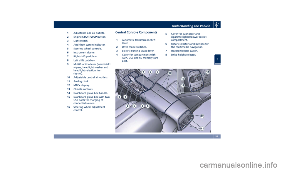
1 Adjustable side air outlets.
2 Engine START/STOP button.
3 Light switch.
4 Anti-theft system indicator.
5 Steering wheel controls.
6 Instrument cluster.
7 Right shift paddle +.
8 Left shift paddle –.
9 Multifunction lever (windshield
wipers, headlight washer and
headlight selection, turn
signals).
10 Adjustable central air outlets.
11 Analog clock.
12 MTC+ display.
13 Climate controls.
14 Dashboard glove box handle.
15 Dashboard glove box with two
USB ports for charging of
connected source.
16 Steering wheel adjustment
control. Central Console Components 1 Automatic transmission shift
lever.
2 Drive mode switches.
3 Electric Parking Brake lever.
4 Cover for compartment with
AUX, USB and SD memory card
port. 5 Cover for cupholder and
cigarette lighter/power socket
compartment.
6 Rotary selectors and buttons for
the multimedia navigation.
7 Hazard flashers switch.
8 Drive height selector.Understanding the Vehicle
3
95
Page 154 of 436
open, then adjust the sunroof opening
to minimize the buffeting.
Ignition Off Operation The power sunroof controls will
remain active for up to approximately
ten minutes after the ignition switch is
in OFF position. Opening either front
door will cancel this feature. The
ignition system timing can be set using
the MTC+ System (see “MTC+ Settings”
in section “Dashboard Instruments and
Controls”).
Sunroof Maintenance Use only a nonabrasive cleaner and a
soft cloth to clean the glass panel. HomeLink ®
(optional) HomeLink ®
replaces up to three
hand-held transmitters operating the
automatic devices that open garage
doors and gates, enable/disable the
lighting or security systems. The
HomeLink ®
unit is powered by your
vehicle's 12 Volt battery. The
HomeLink ®
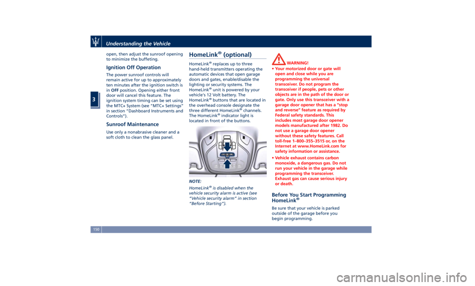
buttons that are located in
the overhead console designate the
three different HomeLink ®
channels.
The HomeLink ®
indicator light is
located in front of the buttons.
NOTE:
HomeLink ®
is disabled when the
vehicle security alarm is active (see
“Vehicle security alarm” in section
“Before Starting”). WARNING!
• Your motorized door or gate will
open and close while you are
programming the universal
transceiver. Do not program the
transceiver if people, pets or other
objects are in the path of the door or
gate. Only use this transceiver with a
garage door opener that has a “stop
and reverse” feature as required by
Federal safety standards. This
includes most garage door opener
models manufactured after 1982. Do
not use a garage door opener
without these safety features. Call
toll-free 1–800–355–3515 or, on the
Internet at www.HomeLink.com for
safety information or assistance.
• Vehicle exhaust contains carbon
monoxide, a dangerous gas. Do not
run your vehicle in the garage while
programming the transceiver.
Exhaust gas can cause serious injury
or death.
Before You Start Programming
HomeLink ®
Be sure that your vehicle is parked
outside of the garage before you
begin programming.Understanding the Vehicle
3
150
Page 171 of 436
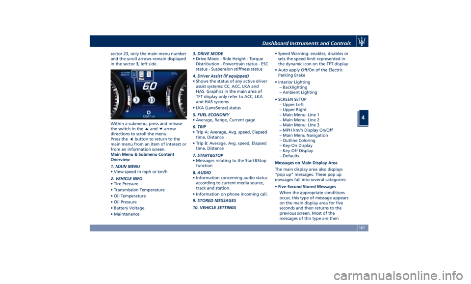
sector 23, only the main menu number
and the scroll arrows remain displayed
in the sector 3 , left side.
Within a submenu, press and release
the switch in the
and arrow
directions to scroll the menu.
Press the
button to return to the
main menu from an item of interest or
from an information screen.
Main Menu & Submenu Content
Overview
1. MAIN MENU
• View speed in mph or km/h
2. VEHICLE INFO
• Tire Pressure
• Transmission Temperature
• Oil Temperature
• Oil Pressure
• Battery Voltage
• Maintenance 3. DRIVE MODE
• Drive Mode - Ride Height - Torque
Distribution - Powertrain status - ESC
status - Suspension stiffness status
4. Driver Assist (if equipped)
• Shows the status of any active driver
assist systems: CC, ACC, LKA and
HAS. Graphics in the main area of
TFT display only refer to ACC, LKA
and HAS systems
• LKA (LaneSense) status
5. FUEL ECONOMY
• Average, Range, Current gage
6. TRIP
• Trip A: Average, Avg. speed, Elapsed
time, Distance
• Trip B: Average, Avg. speed, Elapsed
time, Distance
7. START&STOP
• Messages relating to the Start&Stop
function
8. AUDIO
• Information concerning audio status
according to current media source,
track and station.
• Information on phone incoming call.
9. STORED MESSAGES
10. VEHICLE SETTINGS • Speed Warning: enables, disables or
sets the speed limit represented in
the dynamic icon on the TFT display
• Auto apply Off/On of the Electric
Parking Brake
• Interior Lighting
– Backlighting
– Ambient Lighting
• SCREEN SETUP
– Upper Left
– Upper Right
– Main Menu: Line 1
– Main Menu: Line 2
– Main Menu: Line 3
– MPH km/h Display On/Off
– Main Menu Navigation
– Outline Coloring
– Key-On Display
– Key-Off Display
– Defaults
Messages on Main Display Area
The main display area also displays
"pop up" messages. These pop up
messages fall into several categories:
• Five-Second Stored Messages
When the appropriate conditions
occur, this type of message appears
on the main display area for five
seconds and then returns to the
previous screen. Most of the
messages of this type are thenDashboard Instruments and Controls
4
167
Page 175 of 436
4. DRIVER ASSIST (if equipped)
Press and release the switch in the
or arrow directions until this
menu item is displayed.
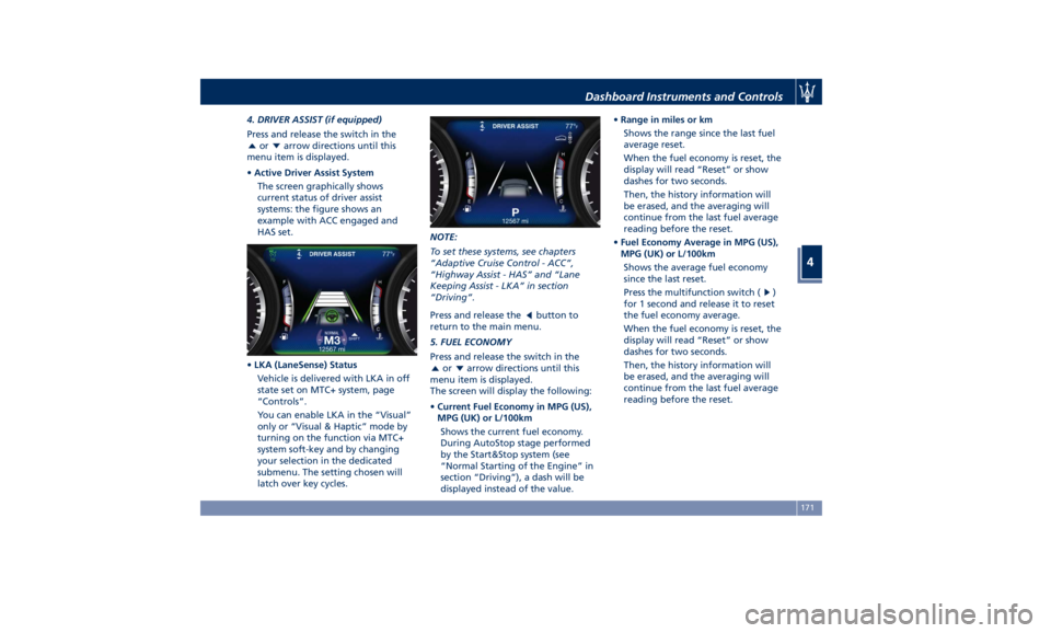
• Active Driver Assist System
The screen graphically shows
current status of driver assist
systems: the figure shows an
example with ACC engaged and
HAS set.
• LKA (LaneSense) Status
Vehicle is delivered with LKA in off
state set on MTC+ system, page
“Controls”.
You can enable LKA in the “Visual”
only or “Visual & Haptic” mode by
turning on the function via MTC+
system soft-key and by changing
your selection in the dedicated
submenu. The setting chosen will
latch over key cycles. NOTE:
To set these systems, see chapters
“Adaptive Cruise Control - ACC”,
“Highway Assist - HAS” and “Lane
Keeping Assist - LKA” in section
“Driving”.
Press and release the
button to
return to the main menu.
5. FUEL ECONOMY
Press and release the switch in the
or arrow directions until this
menu item is displayed.
The screen will display the following:
• Current Fuel Economy in MPG (US),
MPG (UK) or L/100km
Shows the current fuel economy.
During AutoStop stage performed
by the Start&Stop system (see
“Normal Starting of the Engine” in
section “Driving”), a dash will be
displayed instead of the value. • Range in miles or km
Shows the range since the last fuel
average reset.
When the fuel economy is reset, the
display will read “Reset” or show
dashes for two seconds.
Then, the history information will
be erased, and the averaging will
continue from the last fuel average
reading before the reset.
• Fuel Economy Average in MPG (US),
MPG (UK) or L/100km
Shows the average fuel economy
since the last reset.
Press the multifunction switch (
)
for 1 second and release it to reset
the fuel economy average.
When the fuel economy is reset, the
display will read “Reset” or show
dashes for two seconds.
Then, the history information will
be erased, and the averaging will
continue from the last fuel average
reading before the reset.Dashboard Instruments and Controls
4
171
Page 176 of 436
Press and release the button to
return to the main menu.
6. TRIP
Press and release the switch in the
or arrow directions until this
menu item is displayed.
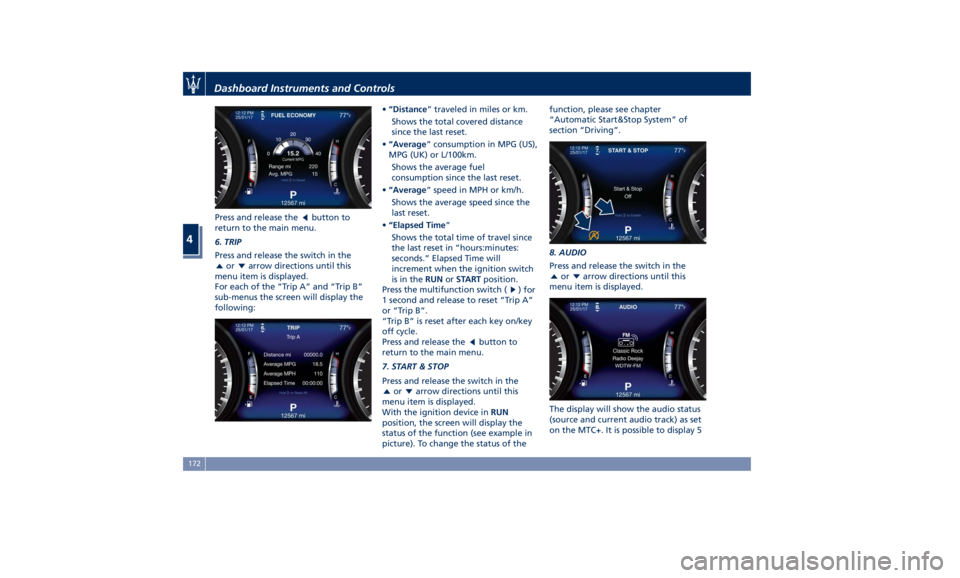
For each of the “Trip A” and “Trip B”
sub-menus the screen will display the
following: • “Distance ” traveled in miles or km.
Shows the total covered distance
since the last reset.
• “Average ” consumption in MPG (US),
MPG (UK) or L/100km.
Shows the average fuel
consumption since the last reset.
• “Average ” speed in MPH or km/h.
Shows the average speed since the
last reset.
• “Elapsed Time ”
Shows the total time of travel since
the last reset in “hours:minutes:
seconds.” Elapsed Time will
increment when the ignition switch
is in the RUN or START position.
Press the multifunction switch (
) for
1 second and release to reset “Trip A”
or “Trip B”.
“Trip B” is reset after each key on/key
off cycle.
Press and release the
button to
return to the main menu.
7. START & STOP
Press and release the switch in the
or arrow directions until this
menu item is displayed.
With the ignition device in RUN
position, the screen will display the
status of the function (see example in
picture). To change the status of the function, please see chapter
“Automatic Start&Stop System” of
section “Driving”.
8. AUDIO
Press and release the switch in the
or arrow directions until this
menu item is displayed.
The display will show the audio status
(source and current audio track) as set
on the MTC+. It is possible to display 5Dashboard Instruments and Controls
4
172
Page 186 of 436
WARNING!
Do not drive with this warning light
on. Check that the fuel filler cap is
tightened correctly.
Electric Parking Brake Failure Warning
Light
This
warning light and
related
message illuminate when
there is an EPB system failure.
The failure could also
completely or partially block the
vehicle because the parking brake
could remain on even after it has been
automatically or manually disengaged
though its controls.
If it is still possible to use the vehicle
(parking brake not engaged) drive to
the nearest Authorized Maserati
Dealer and remember to performing
each operation/command that the
electric parking brake is not
functioning.
Start&Stop Disable Indicator
This indicator illuminates
when Start&Stop is turned off
through the controls located
on the right side of the
steering wheel or through the relevant
soft-key of the MTC+. See chapter “Automatic Start&Stop System” of
section “Driving” for further
information.
Start&Stop Failure Warning Light
This warning light illuminates
when there is a failure in the
Start&Stop system. Switch the
engine on or off using the
normal procedure with the ignition
device START/STOP and have the
vehicle checked at an Authorized
Maserati Dealer .
Scheduled Maintenance (Service)
Indicator
This indicator illuminates and
a message flashes on the
display for approximately 5
seconds after an acoustic
signal to indicate that the next
scheduled maintenance is due or is
already overdue.
Unless reset, the message will continue
to display each time you cycle the
ignition to the RUN position.
To turn off the message temporarily,
press and release the
button on the
steering wheel. To reset the service
indicator system, please visit an
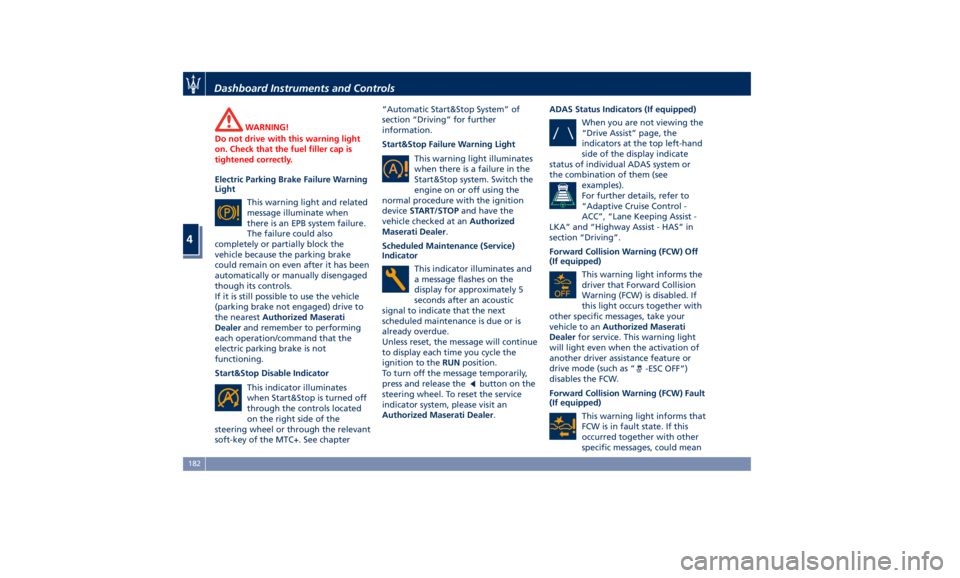
Authorized Maserati Dealer . ADAS Status Indicators (If equipped)
When you are not viewing the
“Drive Assist” page, the
indicators at the top left-hand
side of the display indicate
status of individual ADAS system or
the combination of them (see
examples).
For further details, refer to
“Adaptive Cruise Control -
ACC”, “Lane Keeping Assist -
LKA” and “Highway Assist - HAS” in
section “Driving”.
Forward Collision Warning (FCW) Off
(If equipped)
This warning light informs the
driver that Forward Collision
Warning (FCW) is disabled. If
this light occurs together with
other specific messages, take your
vehicle to an Authorized Maserati
Dealer for service. This warning light
will light even when the activation of
another driver assistance feature or
drive mode (such as “
-ESC OFF”)
disables the FCW.
Forward Collision Warning (FCW) Fault
(If equipped)
This warning light informs that
FCW is in fault state. If this
occurred together with other
specific messages, could meanDashboard Instruments and Controls
4
182
Page 232 of 436
Normal Starting of the
Engine WARNING!
It is dangerous to run the engine in an
enclosed area. The engine consumes
oxygen and discharges carbon
dioxide, carbon monoxide and other
toxic gases in the atmosphere.
WARNING!
California Proposition 65
Operating, servicing and maintaining
a passenger vehicle or off-road vehicle
can expose you to chemicals including
such as, engine exhaust, carbon
monoxide, phthalates and lead, that
which are known to the State of
California to cause cancer and birth
defects or other reproductive harm. To
minimize exposure, avoid breathing
exhaust, do not idle the engine except
as necessary, service your vehicle in a
well-ventilated area and wear gloves
or wash your hands frequently when
servicing your vehicle. For more
information go to: www.P65Warnings.ca.gov/passenger-
vehicle
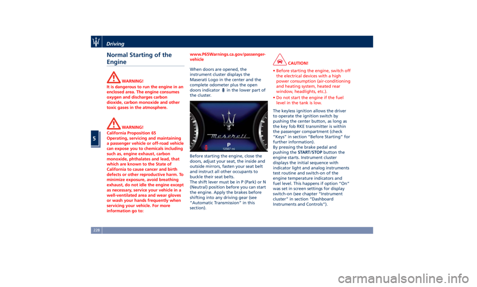
When doors are opened, the
instrument
cluster displays the
Maserati
Logo in the center and the
complete odometer plus the open
doors indicator
in the lower part of
the cluster.
Before starting the engine, close the
doors, adjust your seat, the inside and
outside mirrors, fasten your seat belt
and instruct all other occupants to
buckle their seat belts.
The shift lever must be in P (Park) or N
(Neutral) position before you can start
the engine. Apply the brakes before
shifting into any driving gear (see
“Automatic Transmission” in this
section). CAUTION!
• Before starting the engine, switch off
the electrical devices with a high
power consumption (air-conditioning
and heating system, heated rear
window, headlights, etc.).
• Do not start the engine if the fuel
level in the tank is low.
The keyless ignition allows the driver
to
operate the ignition
switch by
pushing the center button, as long as
the key fob RKE transmitter is within
the passenger compartment (check
“Keys” in section “Before Starting” for
further information).
By pressing the brake pedal and
pushing the START/STOP button the
engine starts. Instrument cluster
displays the initial sequence with
indicator light and analog instruments
test routine and switch-on of the
engine temperature indicators and
fuel level. This happens if option “On”
was set in screen settings for display
switch-on (see chapter “Instrument
cluster” in section “Dashboard
Instruments and Controls”).Driving
5
228
Page 233 of 436
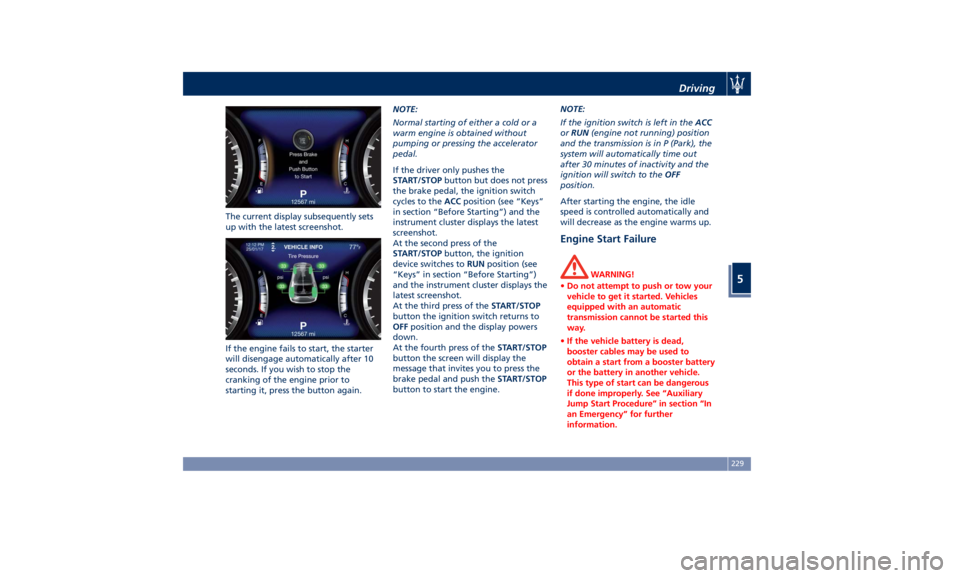
The current display subsequently sets
up with the latest screenshot.
If the engine fails to start, the starter
will disengage automatically after 10
seconds. If you wish to stop the
cranking of the engine prior to
starting it, press the button again. NOTE:
Normal starting of either a cold or a
warm engine is obtained without
pumping or pressing the accelerator
pedal.
If the driver only pushes the
START/STOP button but does not press
the brake pedal, the ignition switch
cycles to the ACC position (see “Keys”
in section “Before Starting”) and the
instrument cluster displays the latest
screenshot.
At the second press of the
START/STOP button, the ignition
device switches to RUN position (see
“Keys” in section “Before Starting”)
and the instrument cluster displays the
latest screenshot.
At the third press of the START/STOP
button the ignition switch returns to
OFF position and the display powers
down.
At the fourth press of the START/STOP
button the screen will display the
message that invites you to press the
brake pedal and push the START/STOP
button to start the engine. NOTE:
If the ignition switch is left in the ACC
or RUN (engine not running) position
and the transmission is in P (Park), the
system will automatically time out
after 30 minutes of inactivity and the
ignition will switch to the OFF
position.
After starting the engine, the idle
speed is controlled automatically and
will decrease as the engine warms up.
Engine Start Failure WARNING!
• Do not attempt to push or tow your
vehicle to get it started. Vehicles
equipped with an automatic
transmission cannot be started this
way.
• If the vehicle battery is dead,
booster cables may be used to
obtain a start from a booster battery
or the battery in another vehicle.
This type of start can be dangerous
if done improperly. See “Auxiliary
Jump Start Procedure” in section “In
an Emergency” for further
information.Driving
5
229