tow MAZDA 232 1990 Workshop Manual Suplement
[x] Cancel search | Manufacturer: MAZDA, Model Year: 1990, Model line: 232, Model: MAZDA 232 1990Pages: 677, PDF Size: 61.19 MB
Page 4 of 677
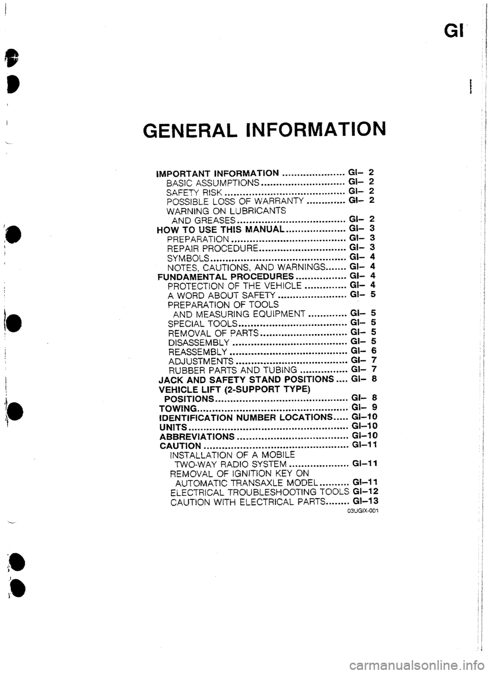
GENERAL INFORMATION
IMPORTANT INFORMATION ..................... GI- 2
BASIC ASSUMPTtONS ............................ a- 2
SAFETY RlSK
........................................ GI- 2
POSSBLE LOSS OF WARRANTY ............. GI- 2
WARNiNF ON LUBRICANTS
AND GREASES .................................... GI- 2
HOW TO USE THIS MANUAL.. .................. Gl- 3
PREPARATION ...................................... Gl- 3
REPAIR PROCEDURE ............................. Gl- 3
SYMBOLS
............................................. a- 4
NOTES, CAUTIONS, AND WARNINGS ....... Gl- 4
FUNDAMENTAL PROCEDURES ................. Gl- 4
PROTECTION OF THE VEHICLE .............. Gi- 4
A WORD ABOUT SAFETY ....................... Gl- 5
PREPARATION OF TOOLS
AND MEASURING EQUIPMENT ............. GI- 5
SPECIAL TOOLS
.................................... Gt- 5
REMOVAL OF PARTS
............................. GI- 5
DISASSEMBLY ...................................... Gi- 5
REASSEMBLY ....................................... Gl- 6
ADJUSTMENTS
..................................... GC- 7
RUBBER PARTS AND TUBING ................ Gl- 7
JACK AN5 SAFETY STAN5 POSITDNS .... Gl- 8
VEHICLE LIFT (Z-SUPPORT TYPE)
POSITIONS ............................................ GI- 8
TOWING .................................................. GL 9
IDENTIFICATION NUMBER LOCATIONS ..... GI-10
UNITS
..................................................... GI-I 0
ABBREVIATIONS ..................................... Gl-I 0
CAUTION ................................................ Gl-I 1
1NSTALLATtON OF A MOBlLE
TWO-WAY RADIO SYSTEM .................... GI-II
REMOVAL OF tGNIT1ON KEY ON
AUTOMATIC TRANSAXLE MODEL .......... Gl-11
ELECTRICAL TROUBLESHOOTlNG TOOLS GI-12
CAUTION WITH ELECTRICAL PARTS ........ Gl-13
03UGIX-001
Page 12 of 677
TOWING GI
i
e
I
I
: -
I
1
1
t
I
$
t
WHEEL tiOLLtES
I I 03UGIX-002
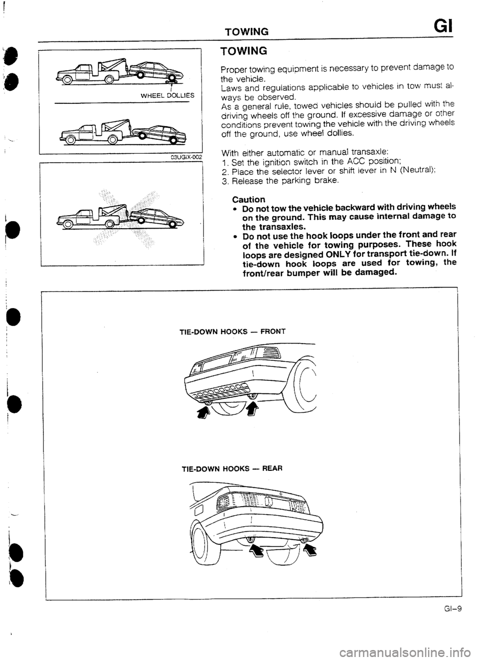
TOWING
Proper towing equipment is necessary to prevent damage to
the vehicle.
Laws and regulations applicable to vehicles in tow
must al-
ways be observed.
As a general rule, towed vehicles should be pulled with the
driving wheels off the ground. If excessive damage or other
conditions prevent towing the vehicle with the driving wheels
off the ground, use wheel dollies.
With either automatic or manual transaxle:
1, Set the ignition switch in the ACC position;
2. Place the selector lever or shift lever in N (Neutral);
3. Release the parking brake.
Caution
l 50 not tow the vehicle backward with driving wheels
on the ground. This may cause internal damage to
the transaxles.
l 50 not use the hook loops under the front and rear
of the vehicle for towing purposes These hook
loops are designed ONLY for transport tie-down. If
tie-down hook loops are used fur towing, the
front/rear bumper wiIl be damaged.
TIE-DOWN HOOKS - FRONT
TIE-DOWN HOOKS - REAR
Page 22 of 677
SCHEDULED MAINTENANCE SERVICES (Australia) A
SCHEDULED MAINTENANCE SERVICES (Australia)
Chart symbols:
I : Inspect: Visual examination or functiona! measurement of a system’s operation (Performance)
A: Adjust
R: Replace or change
T : Tighten
Note
l As the result of visual examination or functional measurement of a system’s operation (Per-
formance), correct, clean or replace as required.
REMARKS:
After 90,000 km or 72 months, continue to follow
the described maintenance items and intervals periodically.
As
“I
*2
*3
“4
l 5 for *
marked items in this maintenance chart please pay attention to the following points.
If the vehicfe is operated under the foltowing conditions, it is suggested that
the engine oil and oil f&r
be changed more often that at usual recommended intervals.
a> Driving in dusty condrt,ons.
b) Extended periods of idling
or low speed operation.
c) Driving for a prolonged period iti coid temperatures or driving only short distances regularly.
Replacement of the timing belt is required at every 105,000 km. failure to replace the timing belt may
result in damage to the engine.
If the vehicle is operated in very dusty or sandy areas, inspect and, if necessary, repface more often
than at usual recommended intervals.
Adjust or inspect alternator and water pump drive belt, and power steering and air conditioner drive belt
if equipped.
Replace every two years.
If there has been continuous hard driving, mountain driving, or if the brakes are used extensively or the
vehicle is operated in extremely humid climates, the brake fluid shotlid be changed annually.
Emission Control and Related Systems
The ignition and fuel systems are vitally important to the proper operation of the emission control and related
system, as well as for efficient engine operation. It is strongly recommended that all servicing related to these
systems be done by your Authorised Mazda Dealer.
93GOAX-702
-
A-3 i
Page 24 of 677
!
i
i
I
i
t-
I
i
i
e
-1
SCHEDULED MAfNTENANCE SERVICES (Europe) A
MAINTENANCE TABLE (Leaded Fuel Model)
Chart symbols:
1 : Inspect: Visual examination and/or functional measurement of system’s operation or performance
A: Adjust: Examination resulting in adjustment or replacement
R: Replace or change
T: Tighten
REMARKS
After 80.000 km or 48 months, continue to foltow the described maintenance at the recommended intervals.
As
*I
*2
“3
*4
*5
*6
*7 for *’
marked items in this’ maintenance chart, note the following points.
Major service interval at 12 months!ZO,OOO km (I 2,000 miles).
Lubrication service based on distance only, 10,000 km (6,000 miles), not time.
Adjust or inspect alternator and water pump drive belt, and power steering and air conditioner drive belt
ii equipped.
Replacement of the timing belt is required every ICQOUO km (60,000 miles). Failure to replace the timing
belt may result in damage to the engine.
If the vehicle is operated under any of the following conditions, it is suggested that the engine
oil and
oil filter be changed more often than the recommended intervals.
a) Driving in dusty conditions.
b) Extended periods of idling or low speed operation.
c) Driving for prolonged periods in cold temperatures or regularly driving only short distances.
If the vehicle is operated in very dusty or sandy areas, inspect and, if necessary, replace more often
than the recommended intervals.
This is a full function check of all electrical systems, i.e, afl lights, washers (inctuding condition of blades)
electric windows sunroof, horn, etc.
Replace every two years.
tf there has been continuous hard driving, mountain driving, or it the brakes are used extensively or the
vehicle is operated in extremely humid climates, the brake fluid should be changed annually.
Emission Control and Related Systems
The ignition and fuel systems are vitally important to the proper operation of the emission control and related
system, as well as for efficient engine operation. It is strongly recommended that all servicing related to these
systems be done by your Authorised Mazda Dealer.
93GOAX-704
A-5
Page 64 of 677
D
D
SUPPLEMENTAL SERVICE iNFORMATION, COMPRESSION 82
SUPPLEMENTAL SERVICE INFORMATION
The following points in this section are changed in comparison with Workshop Manual [Europe (7 203~IO-899,
Australia (I 204-1 U-89F) 1.
Compression
l Inspection
Engine
l Removal
l Engine stand mounting
l Engine stand dismounting
l Ins:attaIion 93GQ32-77 I
COMPRESStON
If the engine exhibits low power, poor fuel economy, or poor idle, check the following:
1. Ignition system (Refer to Section G.)
2. Compression
3. Fuel system (Refer to Section F3.)
93G032-774 93GO32-712
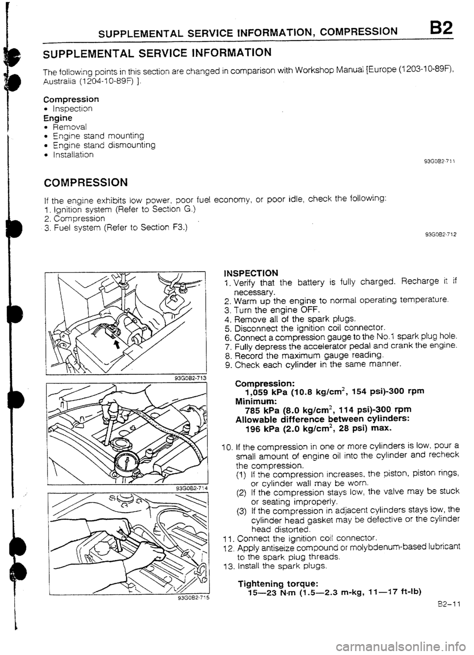
1NSPECTION
1. Verify that the battery is fully charged. Recharge it if
necessary.
2. Warm up the engine to normal operating temperature.
3. Turn the engine OFF.
4. Remove all of the spark plugs.
5. Disconnect the ignition coil connector.
6. Connect a compression gauge to the No.7 spark plug hole.
7. Fully depress the accelerator pedal and crank the engine.
8. Record the maximum gauge reading.
9. Check each cylinder in the same manner.
Compression:
1,059 kPa (IO.8 kg/cm2, 154 psi)-300 rpm
Minimum:
785 kPa (8-O kg/cm2, 114 psi)-300 t-pm
Allowable difference between cylinders:
196 kPa (2.0 kglcm2, 28 psi) max.
IO. If the compression in one or more cylinders is low, pour a
small amount of engine oil into the cylinder and recheck
the compression.
(1) If the compression increases, the piston, piston rings,
or cylinder waII may be worn.
(2) If the compression stays tow, the valve may be stuck
or seating improperly.
(3) If the compression in adjacent cylinders stays low, the
cylinder head gasket may be defective or the cylinder
head distorted.
1 I. Connect the ignition coit connector.
12. Apply antiseize compound or molybdenum-based lubricant
to the spark plug threads.
73. Install the spark plugs.
Tightening torque:
15-23 N-m (1.5-2.3 m-kg, If-17 ft-Ib)
82-11
Page 65 of 677
B2 REMOVAL
REMOVAL
Warning
l Release the fuel pressure. (Refer to Section FZ.)
PROCEDURE
i. Disconnect the negative battery cable.
2. Drain the engine coolant and transaxle oil.
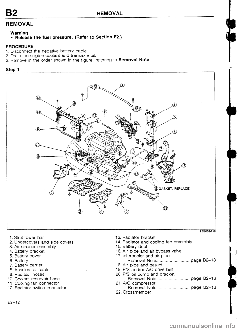
3. Remove in the order shown in the figure, referring to Removaf Note
Step 1
1. Strut tower bar
2. Undercovers and side covers
3. Air cleaner assembly
4.
Battery bracket
5. Battery cover
6. Battery
7. Battery carrier
8. Accelerator cable
9. Radiator hoses
10. Coolant reservoir hose
f I. Cooling fan connector
12. Radiator switch connector
13. Radiator bracket
14. Radiator and coofing fan assembly
15. Battery duct
16. Air pipe and air bypass valve
17. Intercooler and air pipe
Removat Note . . . . . . . . . . . . .._.. m _._._..., page 82-U
18. Air pipe and gasket
19. P/S and/or AK drive bett
20. P/S oil pump and bracket
Removal Note . . . . .._.__.....~..~........ page BZ-13
21. A/C compressor
Removal Note . . . . . .._................... page 82-I 3
22. Crossmember
02-12
Page 86 of 677

INSTALLATION
93G082-7ti
HERE
/+Ju 7
93GOB2-74!
Caution
l Position the hose clamp in the original location on
the hose, and squeeze it lightly with large pliers to
ensure a good fit.
Accelerator cable
1. Install the accelerator
cable.
Tightening torque
@): 7.8-l 1 N4m (80-l 10 cm-kg, 69-95 in-lb)
2. Adjust the cable deflection by turning nuts @ .
Deflection: I-3mm (U&4--0.12 in)
Battery carrier and battery
1 . Install the battery carrier.
Tightening torque:
7.8-l 1 N4m (80-I IO cm-kg, 69-95 in-lb)
2. Install the battery and the battery cover.
3. Install the battery bracket.
Tightening torque:
2.9-5.9 N.m (30-60 cm-kg, 26-52 in-lb)
4. Connect the positive battery cable.
Air cleaner assembly
1. Install the air cleaner assembly.
Tightening torque:
19-25 N-m (1.9-2.6 m-kg, 14-19 ft-lb)
2. Connect the airflow sensor connector.
3. Connect the hoses shown in the figure.
Strut tower bar
I. Instail the strut tower bar.
Tightening torque:
88-108 Narn (9.0-11 .U m-kg, 65-80 ft-lb)
Undercover and side cover
1. Install the undercovers and side covers.
93GOB2-746
82-33
Page 135 of 677
![MAZDA 232 1990 Workshop Manual Suplement F2 FUEL SYSTEM
93GOF2-726
FUEL PUMP RESISTOR/RELAY [BP TURBO]
The fuel pump resistorlretay supplies battery voltage to the
fuel pump when the ECU 11 circuit is OFF, and approx. 1 OV
when the ECU MAZDA 232 1990 Workshop Manual Suplement F2 FUEL SYSTEM
93GOF2-726
FUEL PUMP RESISTOR/RELAY [BP TURBO]
The fuel pump resistorlretay supplies battery voltage to the
fuel pump when the ECU 11 circuit is OFF, and approx. 1 OV
when the ECU](/img/28/57056/w960_57056-134.png)
F2 FUEL SYSTEM
93GOF2-726
FUEL PUMP RESISTOR/RELAY [BP TURBO]
The fuel pump resistorlretay supplies battery voltage to the
fuel pump when the ECU 11 circuit is OFF, and approx. 1 OV
when the ECU 11 circuit is ON. It is mounted on the firewall.
TRANSFER PUMP CONTROL
Outline
The fuel tank is buitt with separate right and left sections to accommodate the. installation of the propeller
shaft. As fuel is puited from the right side of the tank, the transfer pump pumps the fuel from the left to the
right (fuel pumb) side to balance the fuel level.
FUEL IN LEFT TANK
I
FUEL PUMP CONTROL. UNIT
/ TRANSFER PUMP
TRANSFER PUMP SWITCH: OFF
NO FUEL IN LEFT
TANK
FUEL PUMP CONTROL UNIT / TRiNSFER PUMP
TRANSFER PUMP SWITCH: UN
93GOF2-727
Operation 1. Whenever the ignition switch is ON and fuel is in the left (transfer pump)
side of the fuel tank the fuel pump switch is open, the transfer pump circuit in the fuel pump control unit is
closed, and the transfer pump
operates.
2. When the fuel in the left side of the tank drips betow a specified point, the fuel pump switch is grounded
and the transfer pump stops operation.
3. To prevent the transfer pump from
being turned ON and OFF repeatedly, possibly shorting the life of the
pump, when the vehicle is driven on a rough
road and the fuel level is low, there is a ten-second delay
circuit in the control unit to delay the turning ON and OFF the pump.
f2--I 8
Page 157 of 677
![MAZDA 232 1990 Workshop Manual Suplement F2 TROUBLESHOUTING GUIDE
I 22 KNOCKtNG [8P TURBO] I
IESCW-
l Abnormal combustron accompanied by audible “pinging” noise rim
TROUBLESHOOTING HtNTS]
3 incorrect ignition timing (Too advanced) @ MAZDA 232 1990 Workshop Manual Suplement F2 TROUBLESHOUTING GUIDE
I 22 KNOCKtNG [8P TURBO] I
IESCW-
l Abnormal combustron accompanied by audible “pinging” noise rim
TROUBLESHOOTING HtNTS]
3 incorrect ignition timing (Too advanced) @](/img/28/57056/w960_57056-156.png)
F2 TROUBLESHOUTING GUIDE
I 22 KNOCKtNG [8P TURBO] I
IESCW-
l Abnormal combustron accompanied by audible “pinging” noise rim
TROUBLESHOOTING HtNTS]
3 incorrect ignition timing (Too advanced) @ Low octan fuel used
2
Knock control system malfunction @ Air/Fuel mixture lean
3 Carbon deposits in cylinder l Fuel injection amount not correct
3 Overheating l Fuel line pressure decreases while accelerating
TEP INSPECTION ACTlON
1
Connect System Selector to diagnosis connector Yes Go to next step
and set Test Switch to “SELF TEST” and check
for correct ignition timing at idle after warm-up’
ignition timing: BTDC 10 f lo
No Adjust
2 Check if “00” is displayed on Self-Diagnosis Yes Go to next step
Checker with igmtlon switch UN*
No Matf unction Code No. displayed
Check for cause (Refer to specified
check sequence) *
“88” flashes
Check ECU terminal 1 F voltage
Vottage: Approx. 12V
(Ignition switch ON) 0 page FZ-60
4 If OK, replace ECU
W: SELF TEST
4 If not OK, check wiring between
ECU and Self-Diagnosis Checker
3 Check for correct fuel line pressure at idle* Yes Check if fuel Iine pressure decreases
when accelerating quickly
Fuel line pressure:
265-314 kPa (2.7-3.2 kg/cm2, 38-46 psi)
(vacuum hose to pressure regulator dis-
connected) 4 If decreases, check for clogging
between fuel pump and pressure
regulator
e If no decrease, go to next step
No tow pressure Check
fuel line pressure while pinching
fuel return hose
3 If fuel line pressure quickly in-
creases, check pressure
regulator*
4 If fuel line pressure gradually in-
creases, check for clogging be-
tween fuel pump and
pressure
regutator
If not clogged, check fuel pump
maximum pressure*
- -
.-
Refer to 323 Workshop Manual [1203-IO-89f (Europe} or t204-IO-89f (Australia)]. F2-40
Page 159 of 677
![MAZDA 232 1990 Workshop Manual Suplement F2 TROUBLESHOOT1NG GUIDE
25 HIGH OIL CONSUMPTION [BP TURBO]
DESCRIP- 1
l Oil consumption excessive
TION l Exhaust gas white
TROUBLESHOOTING HINTS1
a PCV system malfunctton *
@ Englne malfunctio MAZDA 232 1990 Workshop Manual Suplement F2 TROUBLESHOOT1NG GUIDE
25 HIGH OIL CONSUMPTION [BP TURBO]
DESCRIP- 1
l Oil consumption excessive
TION l Exhaust gas white
TROUBLESHOOTING HINTS1
a PCV system malfunctton *
@ Englne malfunctio](/img/28/57056/w960_57056-158.png)
F2 TROUBLESHOOT1NG GUIDE
25 HIGH OIL CONSUMPTION [BP TURBO]
DESCRIP- 1
l Oil consumption excessive
TION l Exhaust gas white
TROUBLESHOOTING HINTS1
a PCV system malfunctton *
@ Englne malfunction (Oil
working up, working down, or leakage)
3 Oil leakage from turbocharger
ZEP [ INSPECTION Repair or
replace 1 Check if PCV hose, ventilation hose or their at-
taching nipples are separated, damaged,
ciogged, or restricted 2
Check insrde of air hose, air pipe, and intercool-
er for excesstve oil
3 1 Check white exhaust gas visible when ventilation
1 hose or PCV hose removed
1
4 Remove turbocharger and check at oil seals of
compressor and turbine shafi for oil leakage Yes
NO Yes
NO Yes
No Check hoses for clogged
Yes Replace turbocharger
NO
ACTION
Go to next step
Possibly oil working up
Check PCV valve and PCV hose for
clogged
+ If OK, go to next step
e If not UK, repalr or replace
Go to next step
Go to next step
Engine malfunction (Oil working up,
working down, or leakage)
Check foltowing
. Worn piston or cyiinder
l Worn piston ring groove’ l Stuck piston rings* l Worn vatve seal* l Worn valve stem * l Worn vatve guide’
* Refer to 323 Workshop Manual [1203-IO-89F (Europe) or 1204-IO-89F (Australra)].
93GOF2-74:
FZ-42