engine oil MAZDA 232 1990 Suplement User Guide
[x] Cancel search | Manufacturer: MAZDA, Model Year: 1990, Model line: 232, Model: MAZDA 232 1990Pages: 677, PDF Size: 61.19 MB
Page 35 of 677
Bl SUPPLEMENTAL SERVICE tNFORMAT1ON, REMOVAL
SUPPLEMENTAL SERVICE INFORMATION
The following points in this section are changed in comparison with Workshop Manual [Europe (I 203-I U-89F),
Australia (1204- 1 O-89!=)].
Engine
l Removal
l Installation 93GOF31-705
REMOVAL
Warning
w Release the fuel pressure.
PROCEDURE
1. Disconnect the negative battery cable.
2. Drain the engine coolant and transaxle oil.
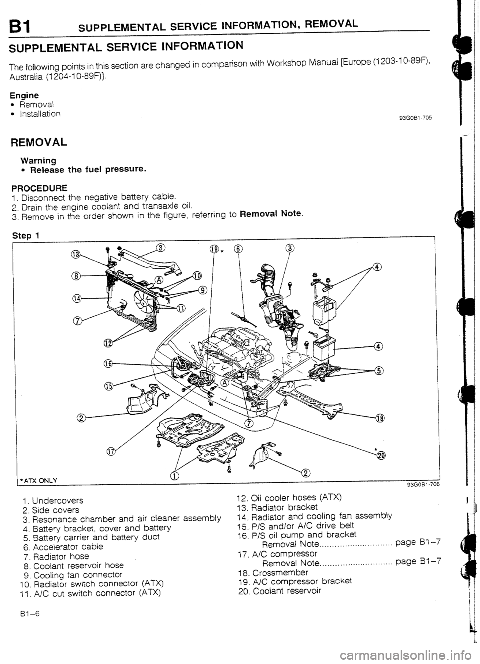
3. Remove in the order shown in the figure, referring to Removal Note.
Step 1
t
I
*ATX ONLY 1
93GOBl-706
1. Undercovers
2. Side covers
3. Resonance chamber and air cleaner assembly
4. Battery bracket, cover and bafiery
5. Battery carrier and battery duct
6. Accelerator cable
7. Radiator hose
8. Coolant reservoir hose
9. Cooling fan connector
IO. Radiator switch connector (ATX)
1 f . A/C cut switch connector (ATX) 12. Oil cooler hoses (ATX)
13. Radiator bracket
14. Radiator and cooling fan assembly
15. P/S and/or A/C drive belt
16. P/S oil pump and bracket
Removal Note .._...._...__......... . . . . . . . page BY -7
17. A/C compressor
Removal Note.. . . . . . . . . . . . . . .._. . . . . . . . ._. page Es1 -7
i 8. Crossmem ber
19. A/C compressor bracket
20. Coolant reservoir
61-6
Page 36 of 677
REMOVAL Bl
/
/
93G05? -72t
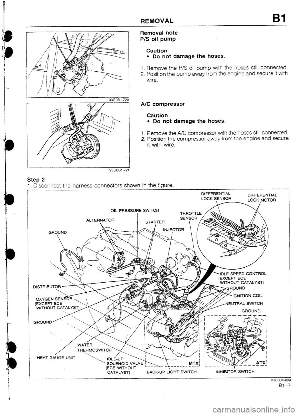
Removal note
P/S oil pump
Caution
l Do not damage the hoses.
I _ Remove the P/S oil pump with the hoses still connected.
2. Position the pump away from the engine and secure it with
wire.
A/C compressor
Caution
l Do not damage the hoses.
1. Remove the AC compressor with the hoses still connected.
2. Position the compressor away from the engine and secure
it with wire.
Step 2
1. Disconnect the harness connectors shown in the figure.
DIFFERENTIAL
DIFFERENTIAL
LUCK SENSOR
OIL PRESSURE SWITCH --- -
GROUND
r, IDLE SPEED CONTROL
NEUTRAL SWITCH
’ SOLENOID VALVE w MTX!
(ECE WITHOUT _--------I
CATALYST) BACK-UP LIGHT SWITCH
\‘C
Y ~55 ATX’
d ---a-- ,-,---1
INHIBITOR SWITCH
Page 52 of 677
INSTALLATION Bl
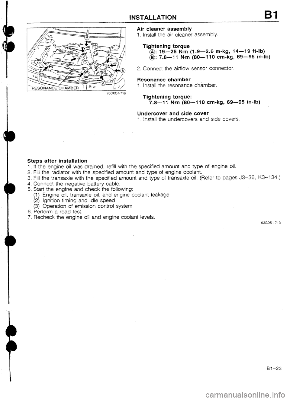
Air cleaner assembly
1. Install the air cleaner assembly.
Tightening torque
@: 19-25 Nm (I-9-2.6 m-kg, 14-19 Mb)
@: 7.8-11 Nm (80~-110 cm-kg, 69-95 in-lb)
2. Connect the airflow sensor connector.
Resonance chamber
1. lnstail the resonance chamber.
Tightening torque:
7.8-W Nm (SO-11 0 cm-kg, 69-95 in-lb)
Undercover and side cuver
1. install the undercovers and side covers.
Steps after installation
1. If the engine oil was drained, refill with the specified amount and type of engine oil.
2. Fill the radiator with the specified amount and type of engine coolant.
3. Fill the transaxle with the specified amount and type of transaxle oil. (Refer to pages J3-36, K3-134.)
4. Connect the negative battery cable.
5. Start the engine and check the following:
(1) Engine oil, transaxle oil, and engine coolant leakage
(2) Ignition timing and idle speed
(3) Operation of emission control system
6. Perform a road test.
7. Recheck the engine oil and engine coolant levels.
93GOSi-719
al-23
Page 54 of 677

B2
ENGINE
(DOHC)
INDEX . . . . . . . ..**......... . . . . . . . ...* . . . . . . . . . . . . . . . . . . . l . BZ- 2
OUTLINE
................................................ BZ- 3
OUTLINE OF CONSTRUCTION.. .............. BZ- 3
SPEClFlCATlONS .................................. BZ- 4
INTERCHANGEABiLITY
.......................... BZ- 5
CYLINDER HEAD
.................................. BZ- 6
CYLINDER BLOCK AND OIL PAN ........... BZ- 7
PISTON ............................................... BZ- 8
FtYWtiEEL .......................................... BZ- 9
CAMSHAFT .......................................... BZ-10
SUPPLEMENTAL SERVICE INFORMATION BZ-11
COMPRESSION
....................................... 82-I 1
INSPECTION ........................................ B2-11
REMOVAL .............................................. BZ-12
PROCEDURE ........................................ BZ-12
ENGINE STAND MOUNTING.. ................... BZ-20
PROCEDURE ........................................ BZ-20
ENGINE STAND DISMOUNTING.. ..............
BZ-21
PROCEDURE ........................................ 82-21
INSTALLATION
....................................... BZ-23
PROCEDURE ........................................ BZ-23
93GOB2-701
Page 58 of 677

c
OUTLINE B2
INTERCHANGEABILITY
The following chart shows interchangeability of the main park of the BP DOHC Turbo engine for the 4WD
model and the BP DOHC Non-Turbo engine for the 2WD model.
Symbols: 5 . Interchangeabie X . . . . Not Interchangeable
Part name interchangeability Remark
1 Cylinder head Shape different
Camshaft oil sea! :
Cylinder head bolt
3
Cyijnder head gasket cl
C$rnder head cover 0
1
Cylinder Cylinder head cover gasket cl
I
Cylinder block 0
block
related Man bearing cap 0
Main bearing support plate 3
OrI pan x Shape different
Trming belt cuver cl
Seal plate 3
Front oil seal I
3
Rear oil seal cl
Crankshaft ‘3
Main bearing 0
Thrust bearing 0
Connecting rod and cap 0
Connecting rod bearing I
0
Crankshaft [ Prston Shape different
related
Piston pin +-- -
c Piston ring cl
Crankshaft pulley 0
Rear cover 3
I Flywheel X Shape different
Flywheel bolt 0
Timing belt
cl
Timing belt Timing belt crank pulley
cl
Camshaft pulley 0 I
related
f Timing belt tensioner and spring
i 0
1, ldter
Camshaft
; Valve timing different
I-LA
Valve I Make - cl
Valve Exhaust 0
related
Vaive sprtng Intake 0
and seat
Exhaust 0
Valve guide cl
Valve seal 0
Oil pump 0
Oil pump gasket 0
Lubrication Oil strainer
0
system Oil strainer gasket
0
related
Oil cooler
0
Oil jet
0
Oil fitter
0
Water pump cl
Cooling
Thermostat
X system Specificatron drfferent
related Radiator X Specificatron different
Cooling fan
X Specification different
^^-^-^ m^- Ix?-5
Page 64 of 677
D
D
SUPPLEMENTAL SERVICE iNFORMATION, COMPRESSION 82
SUPPLEMENTAL SERVICE INFORMATION
The following points in this section are changed in comparison with Workshop Manual [Europe (7 203~IO-899,
Australia (I 204-1 U-89F) 1.
Compression
l Inspection
Engine
l Removal
l Engine stand mounting
l Engine stand dismounting
l Ins:attaIion 93GQ32-77 I
COMPRESStON
If the engine exhibits low power, poor fuel economy, or poor idle, check the following:
1. Ignition system (Refer to Section G.)
2. Compression
3. Fuel system (Refer to Section F3.)
93G032-774 93GO32-712
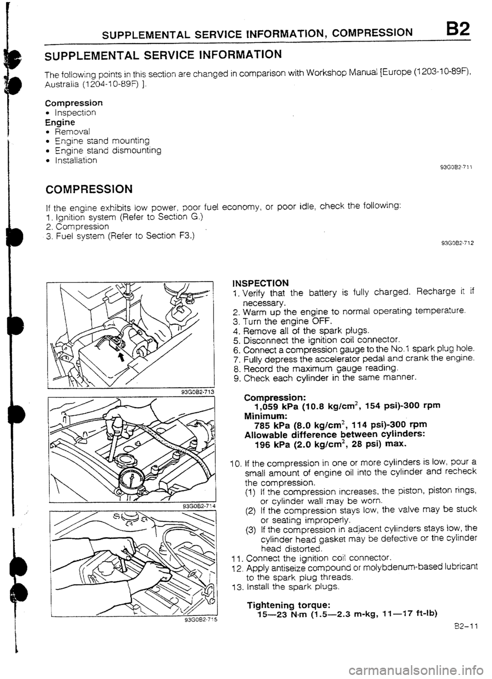
1NSPECTION
1. Verify that the battery is fully charged. Recharge it if
necessary.
2. Warm up the engine to normal operating temperature.
3. Turn the engine OFF.
4. Remove all of the spark plugs.
5. Disconnect the ignition coil connector.
6. Connect a compression gauge to the No.7 spark plug hole.
7. Fully depress the accelerator pedal and crank the engine.
8. Record the maximum gauge reading.
9. Check each cylinder in the same manner.
Compression:
1,059 kPa (IO.8 kg/cm2, 154 psi)-300 rpm
Minimum:
785 kPa (8-O kg/cm2, 114 psi)-300 t-pm
Allowable difference between cylinders:
196 kPa (2.0 kglcm2, 28 psi) max.
IO. If the compression in one or more cylinders is low, pour a
small amount of engine oil into the cylinder and recheck
the compression.
(1) If the compression increases, the piston, piston rings,
or cylinder waII may be worn.
(2) If the compression stays tow, the valve may be stuck
or seating improperly.
(3) If the compression in adjacent cylinders stays low, the
cylinder head gasket may be defective or the cylinder
head distorted.
1 I. Connect the ignition coit connector.
12. Apply antiseize compound or molybdenum-based lubricant
to the spark plug threads.
73. Install the spark plugs.
Tightening torque:
15-23 N-m (1.5-2.3 m-kg, If-17 ft-Ib)
82-11
Page 65 of 677
B2 REMOVAL
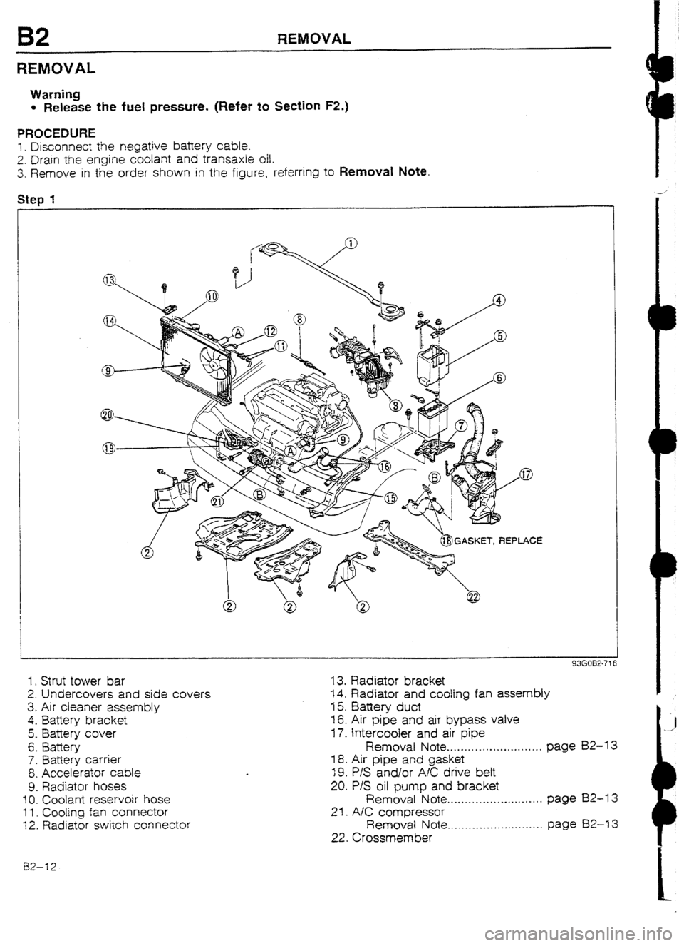
REMOVAL
Warning
l Release the fuel pressure. (Refer to Section FZ.)
PROCEDURE
i. Disconnect the negative battery cable.
2. Drain the engine coolant and transaxle oil.
3. Remove in the order shown in the figure, referring to Removaf Note
Step 1
1. Strut tower bar
2. Undercovers and side covers
3. Air cleaner assembly
4.
Battery bracket
5. Battery cover
6. Battery
7. Battery carrier
8. Accelerator cable
9. Radiator hoses
10. Coolant reservoir hose
f I. Cooling fan connector
12. Radiator switch connector
13. Radiator bracket
14. Radiator and coofing fan assembly
15. Battery duct
16. Air pipe and air bypass valve
17. Intercooler and air pipe
Removat Note . . . . . . . . . . . . .._.. m _._._..., page 82-U
18. Air pipe and gasket
19. P/S and/or AK drive bett
20. P/S oil pump and bracket
Removal Note . . . . .._.__.....~..~........ page BZ-13
21. A/C compressor
Removal Note . . . . . .._................... page 82-I 3
22. Crossmember
02-12
Page 66 of 677
REMOVAL B2
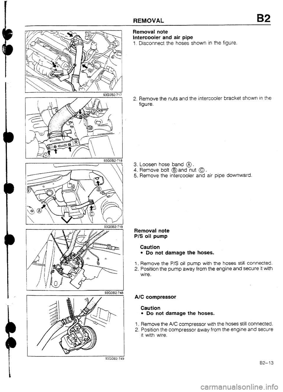
Removal note
intercooler and air pipe
I. Disconnect the hoses shown in the figure.
936032-718
2. Remove the nuts and the intercooler bracket shown in the
figure.
3. Loosen hose band @.
4. Remove bolt @and nut 0.
5. Remove the intercooler and air pipe downward.
RemovaI note
P/S oil pump
Caution
l Do not damage the hoses.
I _ Remove the P/S oil
pump with the hoses still connected.
2. Position the pump away from the engine and secure it with
wire.
93GO52-748
1 93GOB2~749
NC compressor
Caution
l Do not damage the hoses.
1. Remove the AC compressor with the hoses still connected.
2. Position the compressor away from the engine and secure
it with wire.
B2-13
Page 75 of 677

B2 ENGINE STAND DISMOUNTING
93GOB2-7%
93AOB2-077
05WOBX-25
82-22 Water Bypass Pipe
1. Apply a small amount of engine coolant to the new O-ring.
2. install the O-ring on the pipe.
3. InstaIi the water bypass pipe.
A/C Compressor Bracket (if equipped)
1. Install the A/C compressor bracket.
Tightening torque
@: 19-25 N&m (1.9-2.6 m-kg, 14-19 ft-lb)
@: 37-52 Nom (3.8-5.3 m-kg, 27-38 ft-fb)
Exhaust Manifold and Turbocharger Assembly
I= Remove all foreign material from the exhaust manifold con-
tact surfaces.
2. Install a new gasket.
3. Instatl the exhaust manifold and turbocharger assembly.
Tightening torque:
38-46 N-m (3.9-4.7 m-kg, 28-34 ft-lb)
4. Connect the water hose to the water bypass pipe.
5. Connect the water hose and the oil pipe to the cylinder
block.
Tightening torque
@: 12-18 N-m (I -2-l .8 m-kg,
6. Connect the oil return hose to the oi 8.7-13 ft-lb)
I pan.
Exhaust Manifold Insulator
1. Install the exhaust manifold insulator.
Tightening torque:
7.8-I 1 Mm (80-I IO cm-kg, 69-95 in-lb)
Page 87 of 677

82 INSTALLATION
Steps after installation
1. If the engine oil was drained, refill with the specified amount and type of engine oil.
2. Fill the radiator with the specified amount and type of engine coolant.
3. Fill the transaxie with the specified amount and type of transaxle oil. (Refer to page J3-36.)
4. Connect the negative battery cable.
5. Start the engine and check the following:
(I) Engine oiI, transaxle oil, and engine coolant for leakage
(2) Ignition timing and idle speed
(3) Operation of emission control system
6. Perform a road test.
7. Recheck the engine oil and engine coolant levels.
93G032-747
-
BZ-34