change wheel MAZDA 232 1990 Workshop Manual Suplement
[x] Cancel search | Manufacturer: MAZDA, Model Year: 1990, Model line: 232, Model: MAZDA 232 1990Pages: 677, PDF Size: 61.19 MB
Page 33 of 677

BI OUTIAlE
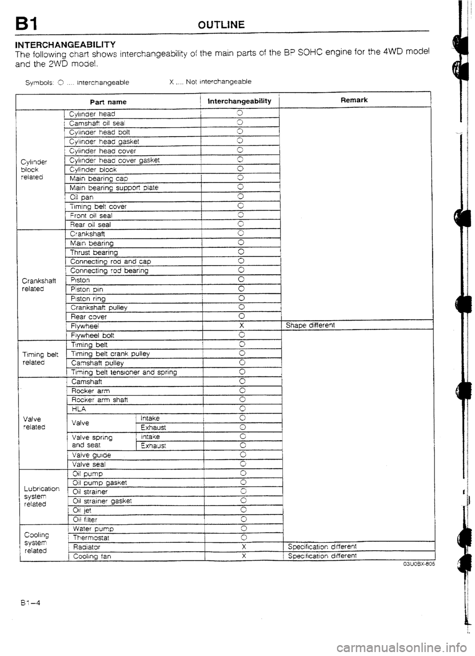
INTERCHANGEABILITY
The following chart shows interchangeability of the main parts of the I3P SOHC engine for the 4WD model
and the 2WD model.
Symbols: 9 ._.. Interchangeable X . . . . Not Interchangeable
Part name
j lnterchangeabiIity Remark
[ Cyirnder head 3
i Camshaft oil sea! cl
f Cylinder head bolt 0
Cyirnaer head gasket 0
Cylrnder head cover 0
Cylinder Cylrnder head cover gasket 3
block Cylinder block 0
related
Main bearing cap 0
Main bearing supper!
plate 0
Oil pan G
Trmjng bett cover
’ Front oil seal G
3
Rear oil seal 0
Crankshaft
0
Main bearing 0
Thrust bearing c
Connecting rod and cap 0
1 Connecting rod bearing 0
Crankshaft Piston
0
related
Piston pm cl
PMon ring
0
1 Crankshaft pulley 0
Rear cover 0
Flywheel X Shape different
Flywheel bolt 0
Timing heft
0
Timing belt Timing belt crank pulley
0
related
Camshaft pulley 0
Timing belt tenstoner and spring Cl
Camshaft
0
Rocker arm 0
Rocker arm shalt 0
HLA 0 I
Valve
retated
Lubrication
system
related Valve ’ intake
Exhaust 0
1
0
Valve spring Intake 0
and seat
Exhaust 0
Valve guide
0
Valve seat 9
Oil pump
0
01 gasket pump
0
Oil strainer r.
Oil strainer gasket G
Oil jet
0
Oil filter 0
Cooling
SyStem related
1 I Water pump
Thermostat
Padi ator
, Cooling fan 0
0
X
X Specification drffereni
1 Speclfrcatlon different
03UOBX-805
BY-4
Page 58 of 677

c
OUTLINE B2
INTERCHANGEABILITY
The following chart shows interchangeability of the main park of the BP DOHC Turbo engine for the 4WD
model and the BP DOHC Non-Turbo engine for the 2WD model.
Symbols: 5 . Interchangeabie X . . . . Not Interchangeable
Part name interchangeability Remark
1 Cylinder head Shape different
Camshaft oil sea! :
Cylinder head bolt
3
Cyijnder head gasket cl
C$rnder head cover 0
1
Cylinder Cylinder head cover gasket cl
I
Cylinder block 0
block
related Man bearing cap 0
Main bearing support plate 3
OrI pan x Shape different
Trming belt cuver cl
Seal plate 3
Front oil seal I
3
Rear oil seal cl
Crankshaft ‘3
Main bearing 0
Thrust bearing 0
Connecting rod and cap 0
Connecting rod bearing I
0
Crankshaft [ Prston Shape different
related
Piston pin +-- -
c Piston ring cl
Crankshaft pulley 0
Rear cover 3
I Flywheel X Shape different
Flywheel bolt 0
Timing belt
cl
Timing belt Timing belt crank pulley
cl
Camshaft pulley 0 I
related
f Timing belt tensioner and spring
i 0
1, ldter
Camshaft
; Valve timing different
I-LA
Valve I Make - cl
Valve Exhaust 0
related
Vaive sprtng Intake 0
and seat
Exhaust 0
Valve guide cl
Valve seal 0
Oil pump 0
Oil pump gasket 0
Lubrication Oil strainer
0
system Oil strainer gasket
0
related
Oil cooler
0
Oil jet
0
Oil fitter
0
Water pump cl
Cooling
Thermostat
X system Specificatron drfferent
related Radiator X Specificatron different
Cooling fan
X Specification different
^^-^-^ m^- Ix?-5
Page 106 of 677

OUTLINE Fl
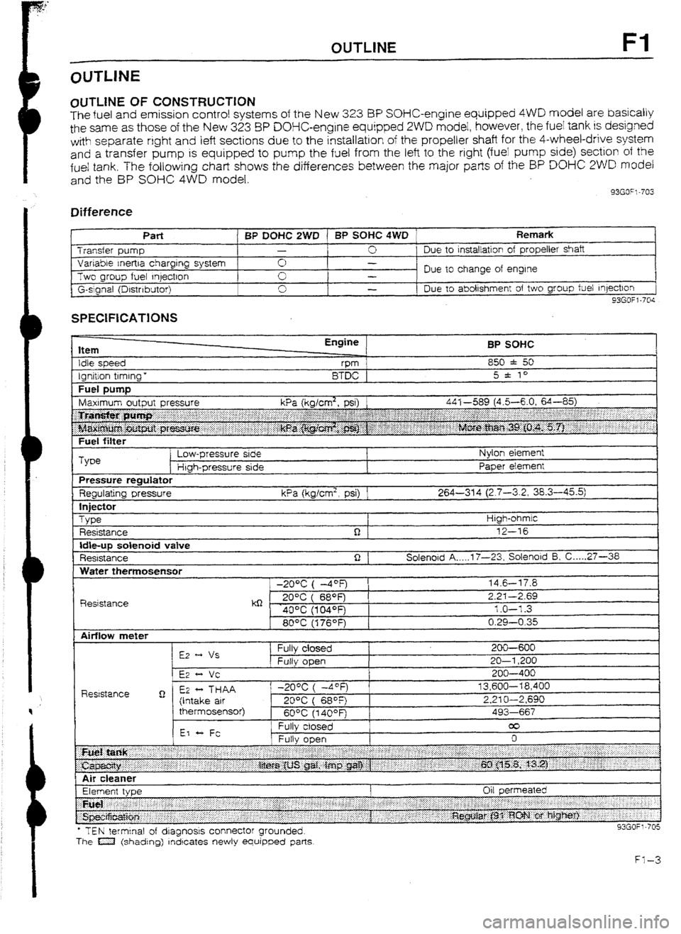
OlJTLlNE OF CONSTRUCTION
The fuel and emission control systems of the New 3.23 BP SOHC-engine equipped 4WD model are basically
the same as those of the New 323 8P DOHC-engine equipped 2WD model, however, the fuel tank is designed
with separate right
and left sections due to the installation of the propeller shaft for the 4-wheel-drive system
and
a transfer pump is equipped to pump the fuel from the left to the right (fuei pump side) section of the
fue! tank. The following chart shows the differences between the major parts of the BP DO% 2WD model
and the BP SOHC 4WD model.
33GO”l-703
Difference
I t
Part BP DOHC 2WD 1 BP SOHC 4WD Remark Transfer pump -
0 Due to
installation of propeller shaft
Variable Inertra charging system 0 -
Two group fuel qectron Due to change of engine
-
G-slgnal (Drstnbutor) 0
I -
Due to abolishment of two group fuel Injection
93GOfl-70s
SPECIFICATIONS
Item
Idle speed
Ignition timing * Engine
vm
BTDC BP SOHC
850 * 50
5 * to
Fuel DUtTlD I
Fuel filter
Type Low-pressure side
Htgh-pressure side Nylon element
Paper element
Pressure regulator
Regulating pressure kPa (kglcm2, psi) 1 264-314 (2.7-3.2, 38.3-45.5)
In
jfXt0r
Type
Resistance High-ohmic
12-16
Idbup solenoid vatve
Resistance Solenoid A _.._. 17-23, Solenoid 5, C ._... 27-36
Water themosensor
R&stance -20% ( -4OF)
kQ - . 20°C ( 689=)
40% (104OFj
80°C (176OF) 14.6-l 7.8
2.2-I -2.69
1.0-l -3
0.29-0.35
l TEN terminal of dragnosrs connector grounded.
The a (shading) rndrcates newly equipped parts
Page 197 of 677

H OUTLINE
OUTLINE
OUTLINE OF CONSTRUCTION
A hydraulic clutch control mechanism is used.
The basic construction is the same as that of 323 2WD model, but there is no interchangeability of parts
except for the release cylinder.
1. An assist/return spring is used on the BP DOHC Turbo model to reduce the required clutch pedal effort..
2. The hydraulic clutch master cylinder for the 8P DOl-lC Turbo model has a built-in check valve.
3. To improve clutch operation feeling and increased parts life, a friction plate and needle roller bearings
are used between the release fork and the release bearing.
93GOHX-704
SPECIFICATIONS
Hem
Clutch control Engine/Transaxle
BP SUHC BP DOHC Turbo
GSMX-R
Hydrautic
Clutch cover
Type
Set load
N (kg, lb) Diaphragm spring
3,846 (392, 862) 5,494 (560, I ,232)
Outer diameter 1
mm (in) 225 (8.858) 230 (9.055)
I 1 nner diameter mm (in)
I 150 (5.906)
I 155 (6.102) I
CI utch disc
Pressure plate side
mm {in) 4.1 (0.161) 3.2 (0.126)
Thickness f
Flywheel side
mm (in) 3.5 (0.138) 3.2 (0. f 26)
I Type I Suspended
I
Clutch pedal LHD 6.55 Pedal
ratio
RHD 6.7
Full stroke mm (in)
I 135 (5.32)
I
Height (With carpet) mm [in)
I I 96-204 (7.72-8.03)
I
Master cylinder Inner diameter
mm {in)
I 15.87 (0.625)
Release cylinder inner diameter
mm (in)
I - 19.05 (0.750)
I
Clutch fluid SAE J1703 or FMVSSI 16 DOT-3
93GOHX-705
H-4
Page 202 of 677

SUPPLEMENTAL SERVICE INFORMATION, TROU8LESHOOTlNG GUIDE H
SUPPLEMENTALSERVICE INFORMATION
The following points in this section are changed in comparison with 323 Workshop Manual (1206IO-89F).
Troubleshooting guide
Clutch fluid (with ABS)
l Replacement
Clutch pedal (BP DOHC Turbo) Clutch release cylinder (with ABS) l Air bleeding
Clutch unit
l Removal I Inspection I installation
Clutch master cylinder
(BP DOW Turbo or with ABS) l Removal I Inspection I installation
93GOHX-710
l Removal I Inspection I Installation (BP DUHC Turbo)
l Air bleeding (with ABS)
l Overhaul (BP DUHC Turbo)
TROUBLESHOOTING GUlDE
Problem
Possibte Cause Remedy Page
Slipping
Clutch disc facing worn excessively
Replace U-l 9
Clutch disc facing surface hardened or oifed
Repair or replace H-l 9
Pressure plate damaged Replace H-19
Diaphragm spring damaged or weakened
Replace H-l 9
Insufficient clutch pedal piay
Adjust H-12
Clutch pedal sticking
Repair or replace U-11
Flywheel damaged
Repair or replace H-19
Faulty
Excessive runout or damaged clutch disc
Replace H-19
disengagement
Clutch disc spiines rusted or worn ’
Remove rust or replace H-l 9
Clutch disc facing oiled
Repair or replace H-19
Diaphragm spring weakened
Reptace H-19
Excessive clutch pedal ptay
Adjust -
Insufficient clutch fluid
Add fluid H-10
Leakage of clutch fluid
Locate and repair or -
replace
Clutch vibrates
Clutch disc facing oiled
Repair or replace H-l 9
when accelerating
Torsion rubbers weakened
u-19 Clutch disc facing hardened or damaged Replace
Repair or replace H-19
Clutch disc facing rivets loose
Replace H-l 9
Pressure plate damaged or excessive runout
Replace H-l 9
Flywheel surface hardened or damaged
Repair or replace H-19
Loose or worn engine mount
Tighten or replace -
Clutch pedal
sticking Pedal shaft not properly lubricated
Lubricate or replace H-l 1
Asistireturn spring damaged or poor adjust
Replace or adjust H-11, 12
Abnormal noise
Clutch release bearing damaged
Replace N-1 9
Poor iubrication of release bearing sleeve
Torsion rubbers weakened Lubricate or replace H-19
Replace u-t9 Excessive crankshaft
end play
Repalr -
Pilot bearing worn or damaged
Replace H-79
Worn pivot points of reiease fork
Repair or replace H-19