wheel torque MAZDA 232 1990 Workshop Manual Suplement
[x] Cancel search | Manufacturer: MAZDA, Model Year: 1990, Model line: 232, Model: MAZDA 232 1990Pages: 677, PDF Size: 61.19 MB
Page 13 of 677

GI IDENTIFICATION NUMBER LOCATIONSIUNITSIABBREVlATlONS
IDENTIFICATCON NUMBER LOCATIONS
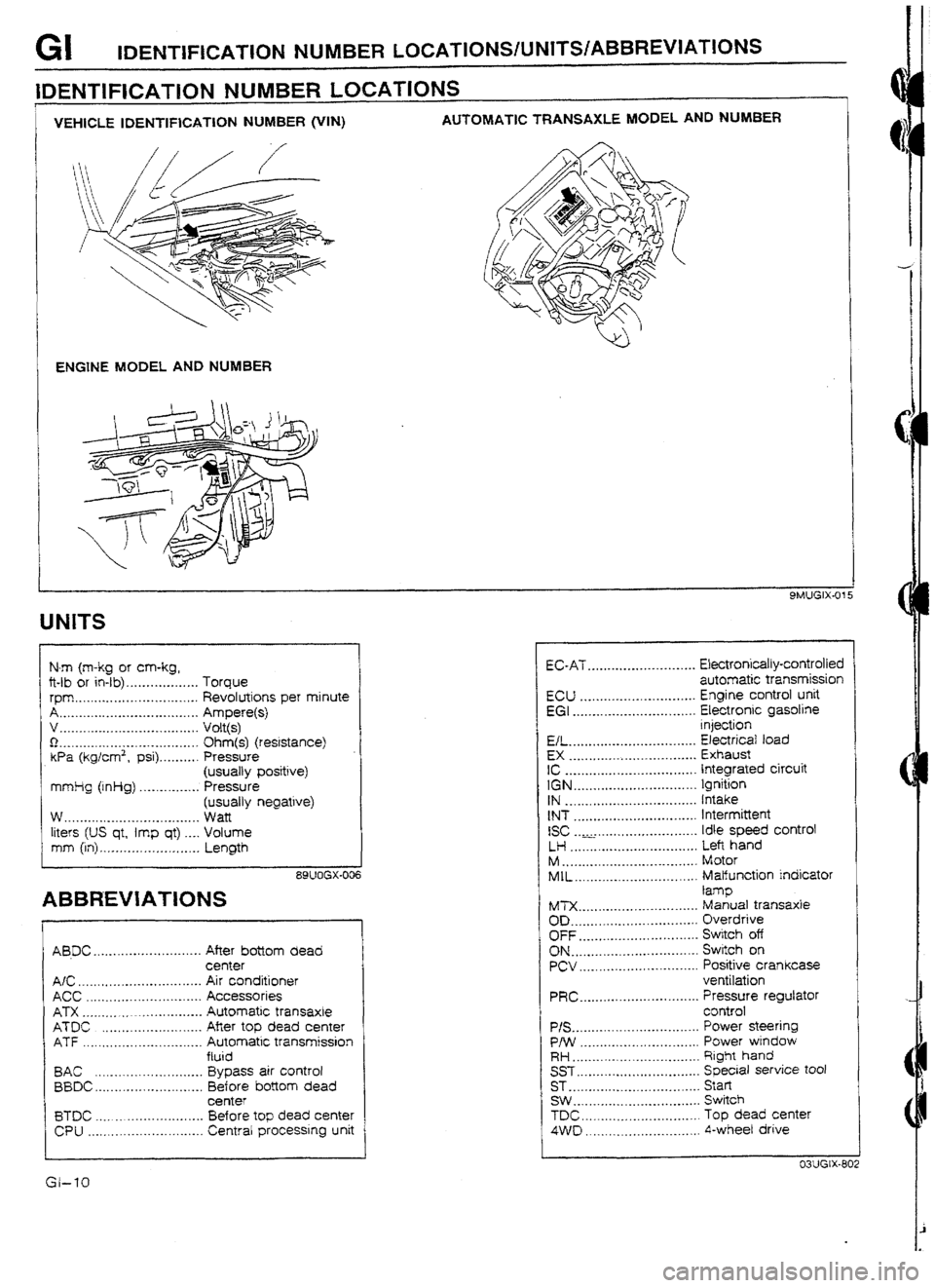
I
VEHKZLE IDENTIFICATION NUMBER @‘IN) AUTOMATIC TRANSAXLE MODEL AND NUM8ER
ENGINE MODEL AND NUMBER
UNlTS
N-m (m-kg or cm-kg,
ft-lb or in-lb) . . . . . .._.......... Torque
rpm ._._..._.. . . . . . . .._.._.._. . .._. Revolutions per minute
A . . .._._._...__.._.._.._. .__...._. . . Ampere(s)
v .._.... .* .*... ..__.._...*. ..*. .*. ,. Volt(s)
0 I.._._............**..-.-*..-....... Ohm(s) (resistance)
Wa (kg/cm2, psi) . . . . . . . . . . Pressure
(usually positive)
mmlig (inHg) . . . . . . .._.._... Pressure
(usually negative)
w . . . ..*.....e*.-..-..-.....*.e..... Watt
liters (US qt, imp qt) .._. Volume
mm (in) ,_._.._._..._.,_. .~. . ..__ Length
89UOGX-006
ABBREVIATIONS
AB.DC ........................... After bottom dead
center
A/C _ .............................. Air conditioner
ACC ............................. Accessories
ATX ............................. Automatic transaxte
ATDC ......................... Afier top dead center
ATF .............................. Automatic transmission
ftuid
BAC ........................... Bypass air control
BBDC.. ......................... Before bottom dead
center
BTDC ........................... Before top dead center
CPU ............................. Central processing unit t EC-AT ........................... Ekctronically-controlled
automatic transmission
ECU ............................. Engine control unit
EGI ............................... Electronic gasotine
injection
EL ................................ Electricaf toad
EX ................................ Exhaust
IC ................................. Integrated circuit
IGN ............................... Ignition
IN ................................. Intake
tNT ............................... Intermittent
ISC ............................. Idle speed control
LH ................................ Left hand
M .................................. Motor
MIL ............................... Malfunction indicator
lamp
tb4TX. ............................. Manual transaxle
OD. ............................... Overdrive
OFF .............................. Switch off
ON ................................ Switch on PCV .............................. Positive crankcase
ventilation
PRC.. ............................ Pressure regulator
control
P/S ................................ Power steering
P/W .............................. Power wtndow
RH.. .............................. Right hand
SST ............................... Special service tool
ST .................................
Start
SW . . .............................. Switch
TDC. ............................. Top dead center
4VVD ............................. 4-wheel drive
Page 203 of 677

H CLUTCH FLUID (WITH ABS)
CLUTCH FLUID (WITH ABS)
PREPARATION
SST
49 0259 770B
For
Wrench, flare nut
m air
bleeding
1
93GOHX-714 93GOHX-712
REPLACEMENT
Note
l A common reservoir is used for the clutch and brake
system fluids.
l The fIuid in the reservoir must be maintained at 314
tevet or higher during replacement.
Caution
l Be careful not to spill the fluid on a painted surface.
If this should happen, wash it off immediately.
l Do not mix different brands of fluid.
l Do not reuse the clutch fluid that was drained.
1. Drain the brake fluid from the master cylinder by pumping
it through a wheel cylinder bleed screw.
2. Remove the bleeder cap from the clutch release cylinder
and attach a vinyl hose to the bleeder plug.
93GOHX-77 3
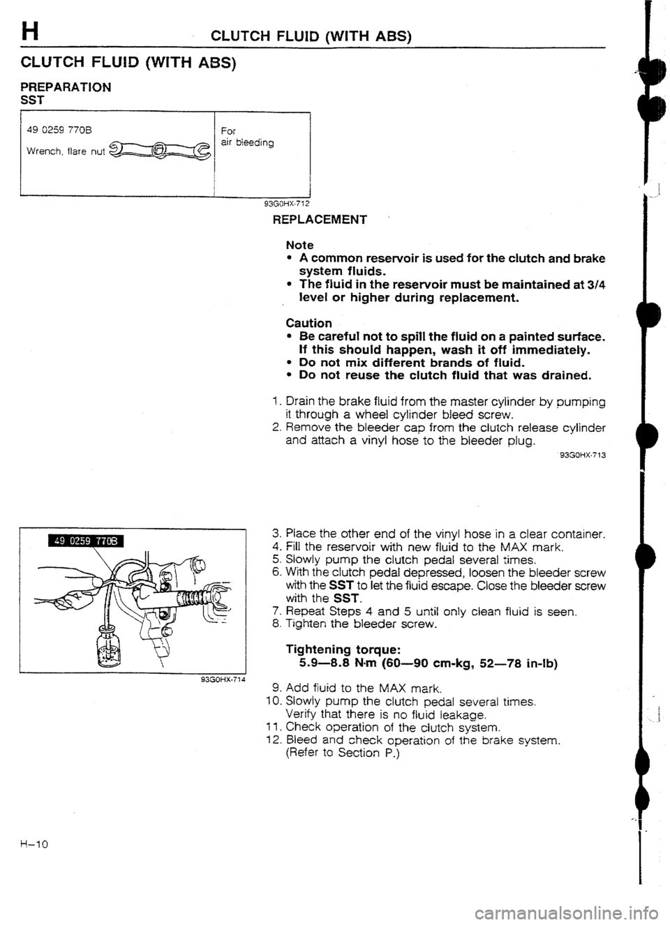
3. Place the other end of the vinyl hose in a clear container.
4. Fill the reservoir with new fluid to the MAX mark.
5. Slowly pump the clutch pedal several times.
6. With the clutch pedal depressed, loosen the bleeder screw
with the SST to let the fluid escape. Close the bleeder screw
with the SST.
7. Repeat Steps 4 and 5 until only clean fluid is seen.
8. Tighten the bleeder screw.
Tightening torque:
5.9-8.8 Nom (60-90 cm-kg, 52-78 in-lb)
9. Add fluid to the MAX mark.
IO. Slowly pump the clutch pedal several times.
Verify that there is no fluid leakage.
11.
Check operation of the clutch system.
12. Bleed and check operation of the brake system.
(Refer to Section PJ
Page 213 of 677

C1UTCf-f UNtT
9MUOHX-032
I
03UOf-lX-028
I
93GOHX-729
I
i
Removal Note
Clutch cover and disc
1. Install the SST.
2. Loosen each bolt one turn at a time in a crisscross pattern
until spring tension is released. Then remove the ciutch cov-
er and disc.
Pilot bearing
1. Remove the pilot bearing with the
SST if necessary.
Flywheel
Note
l After removing the flywheel, inspect for oil leakage
past the crankshaft rear oil seal.
If necessary, replace the oil seal.
1. Hold the flywheel with the SST.
2. Remove the flywheel.
Instalfation Note
Flywheel
1 -Wipe the bolts clean and apply sealant to the bolt threads.
2. Install the flywheel and SST.
3. Tighten the bolts evenly and gradually in the pattern shown.
Tightening torque:
96403 Nmm (9.8-10.5 m-kg, 71-76 ft.lb)
PiIot bearing
Note
l Install the pilot bearing ftush with the flywheeL
I_ Install the new bearing with the SST.
03UOHX-030
H-20
Page 214 of 677

CLUTCW UNIT
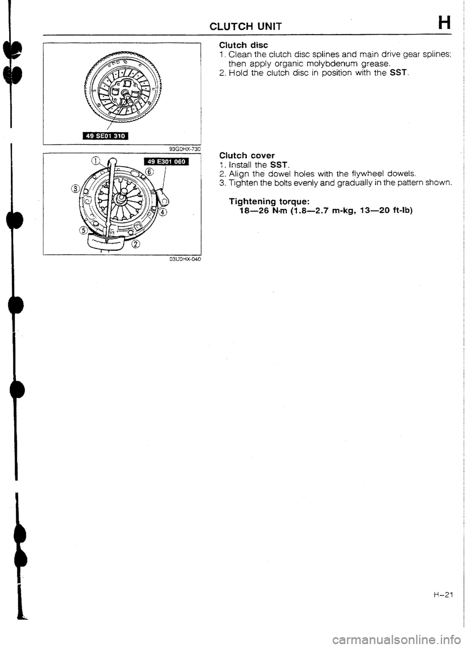
Clutch disc
1. Clean the clutch disc splines and main drive gear spIines;
then apply organic molybdenum grease.
2. Hold
the clutch disc in position with the SST.
Clutch cover
1. Install the SST.
2. Align the
dowel holes with the flywheel dowels.
3. Tighten the
botts evenly and gradually in the pattern shown.
Tightening torque:
18-26 N-m (1.8-2.7 m-kg, 13-20 ft-lb)
EWOHX-040
Ii-21