MAZDA 323 1989 Factory Repair Manual
Manufacturer: MAZDA, Model Year: 1989,
Model line: 323,
Model: MAZDA 323 1989
Pages: 1164, PDF Size: 81.9 MB
MAZDA 323 1989 Factory Repair Manual
323 1989
MAZDA
MAZDA
https://www.carmanualsonline.info/img/28/57053/w960_57053-0.png
MAZDA 323 1989 Factory Repair Manual
Trending: maintenance, manual transmission, display, fuel cap, ground clearance, radio, CD player
Page 941 of 1164
CRUISE CONTROL SYSTEM T
Cont’d
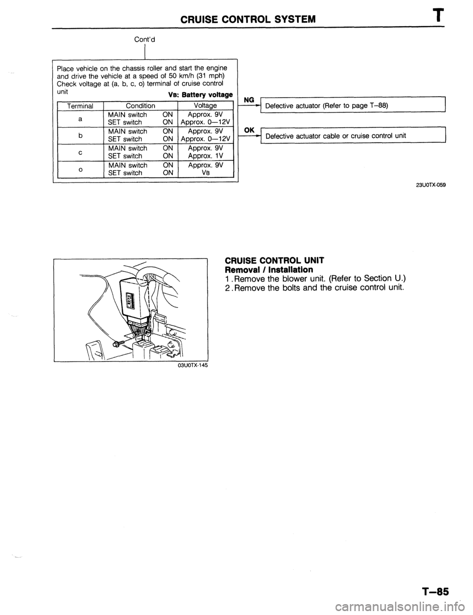
Place vehicle on the chassis roller and start the engine
and drive the vehicle at a speed of 50 km/h (31 mph)
Check voltage at (a, b, c, o) terminal of cruise control
unit Va: Battery voltage
Terminal Condition Voltage
MAIN switch ON
a Approx. 9V
SET switch
ON Approx. 0-12V
b MAIN switch ON Approx. 9V
SET switch ON Approx. 0-12V
MAIN switch ON
C Approx. 9V
SET switch ON
Approx. 1V
0 MAIN switch
Approx. 9V
SET switch Va
OBUOTX
Defective actuator (Refer to page T-88) I
Defective actuator cable or cruise control unit
23UOTX-059
CRUISE CONTROL UNIT
Removal / Installation
1 .Remove the blower unit. (Refer to Section U.)
2. Remove the bolts and the cruise control unit.
T-85
Page 942 of 1164
I
CRUISE CONTROL SYSTEM
s q 0 m
9 e c a
t rpn i j
h
f d b
*
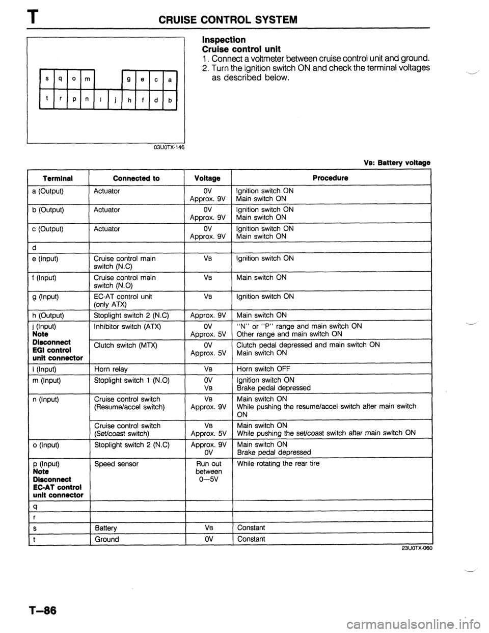
Inspection
Cruise control unit
1. Connect a voltmeter between cruise control unit and ground.
2. Turn the ignition switch ON and check the terminal voltages
as described below.
03UOTX-146
VB: Batterv voltage
c (Output) Actuator
I ov
Approx. 9V
e (Input)
I Cruise control main
I
VB switch (NC)
f (Input)
9 Wv-4 Cruise control main
switch (N.0)
EC-AT control unit
VB
V0
h (Output) (only ATX)
Stoplight switch 2 (N.C) Approx. 9V
i (hW Note I
Inhibitor switch (ATX)
I ov
Approx. 5V Disconnect t
EGI control
Clutch switch (MTX)
ov unit connector Approx. 5V
Cruise control switch
(Set/coast switch) V0
Approx. 5V unit connector
a
S I Battery
I VI3 t
1 Ground I ov Procedure
Ignition switch ON
Main switch ON
Ignition switch ON
Main switch ON
ignition switch ON
Main switch ON
Ignition switch ON
Main switch ON
Ignition switch ON
Main switch ON
“N” or “P” range and main switch ON
Other range and main switch ON
Clutch pedal depressed and main switch ON
Main switch ON
Horn switch OFF
Ignition switch ON
Brake pedal depressed
Main switch ON
While pushing the resumelaccel switch after main switch
ON
Main switch ON
While pushing the set/coast switch after main switch ON
Main switch ON
Brake pedal depressed
While rotating the rear tire
Constant
Constant
23UOTX-OE $0
‘,.__,
_ _-_,’
T-86
Page 943 of 1164
CRUISE CONTROL SYSTEM T
OSUOTX-14
PEDAL HEIGHT
03UOTX-I 4’
OSUOTX-18
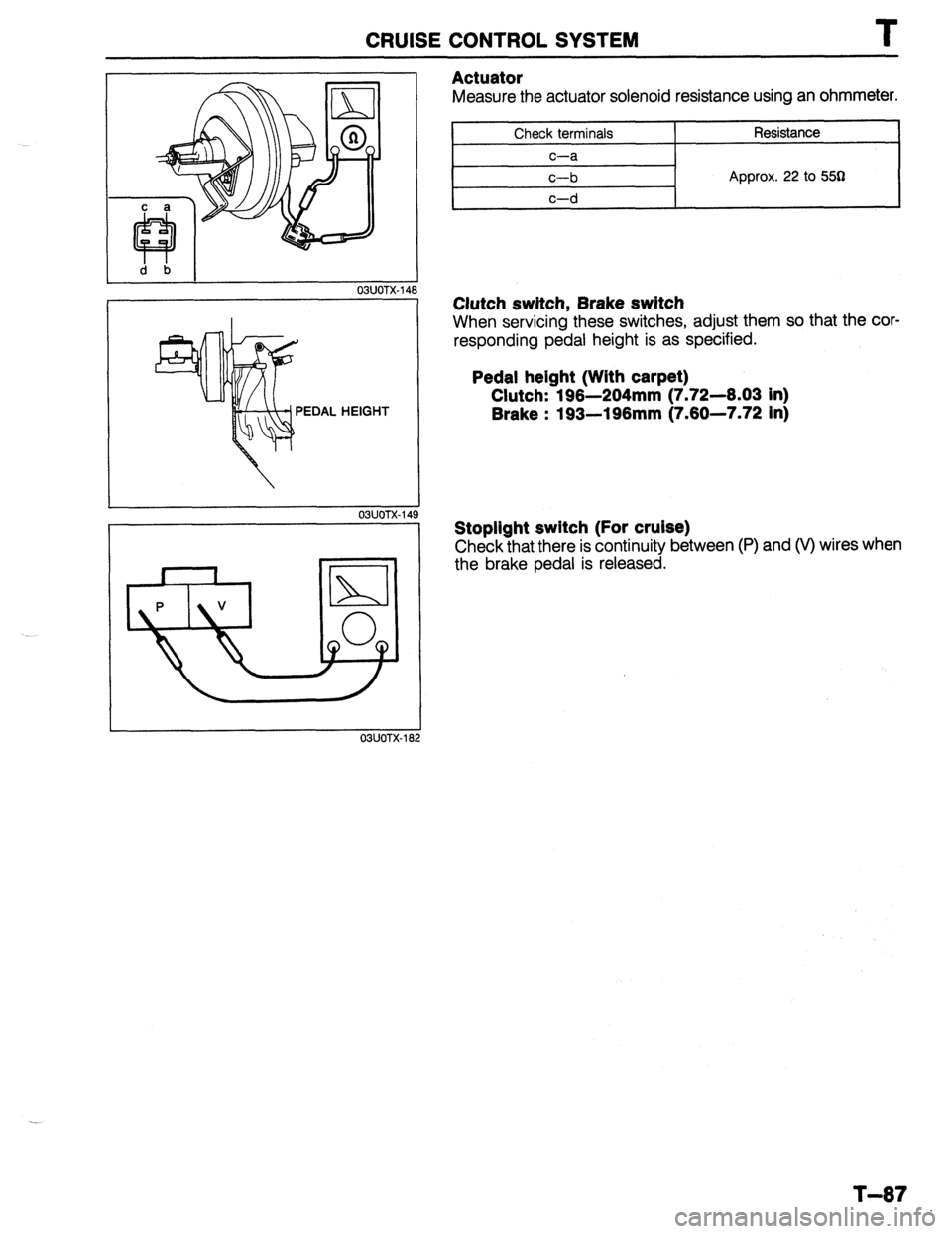
Actuator
Measure the actuator solenoid resistance using an ohmmeter.
Check terminals
c-a
c-b Resistance
Approx. 22 to 553
Clutch switch, Brake switch
When servicing these switches, adjust them so that the cor-
responding pedal height is as specified.
Pedal height (With carpet)
Clutch: 196-204mm (7.72--6.03 in)
Brake : 193-196mm (7.60-7.72 in)
Stoplight switch (For cruise)
Check that there is continuity between (P) and (V) wires when
the brake pedal is released.
T-87
Page 944 of 1164
T HORN
HORN
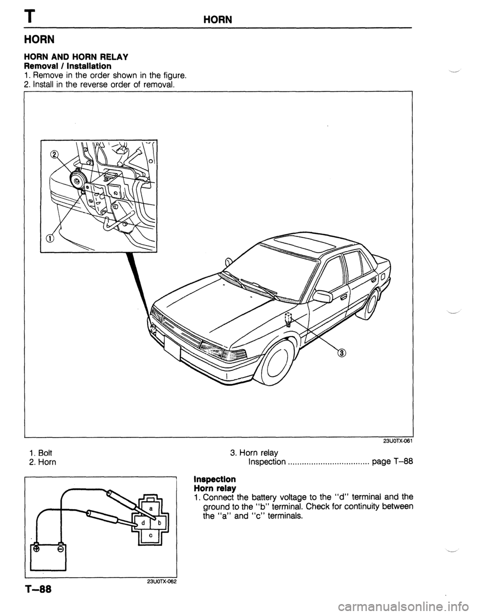
HORN AND HORN RELAY
Removal / Installation
1. Remove in the order shown in the figure.
2. Install in the reverse order of removal.
23UOTX-06
1. Bolt
2. Horn
I I
23UOTX-06
3. Horn relay
Inspection . . . . . . . . . . . . . . . . . . . ..*...**........ page T-88
Inspection
Horn relay
1. Connect the battery voltage to the “d” terminal and the
ground to the “b” terminal. Check for continuity between
the “a” and “c” terminals.
T-88
Page 945 of 1164
AUDIO T
AUDIO
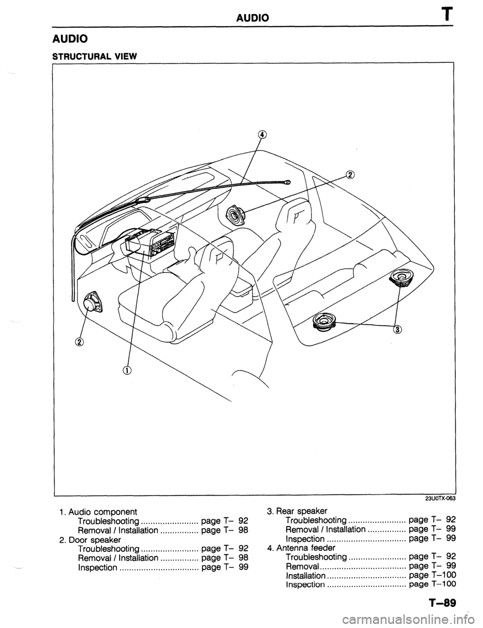
STRUCTURAL VIEW
23UOTX-06:
1. Audio component 3. Rear speaker
Troubleshooting ........................ page T- 92 Troubleshooting ........................ page T- 92
Removal / Installation 99
................ page T- 98 Removal I Installation ................ page T-
2. Door speaker Inspection ................................. page T- 99
Troubleshooting ........................ page T- 92 4. Antenna feeder
Removal / Installation ................ page T- 98 Troubleshooting ........................ page T- 92
Inspection .................................
page T- 99 Removal..
.................................. page T- 99
Installation ................................. page T-100
Inspection ................................. page T-100
T-89
Page 946 of 1164
T AUDIO
RADIO, CASSETTE TAPE PLAYER RADIO
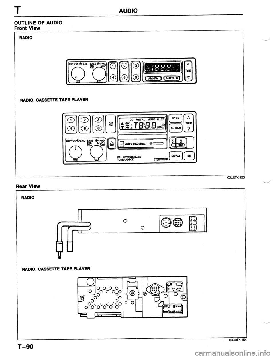
OUTLINE OF AUDIO
Front View
RADIO
II 0 : ’
/
I ’
0 ul. : I
1 , Rear View
RADIO, CASSETTE TAPE PLAYER
I 03lJoTx-154
.-’
T-90
Page 947 of 1164
AUDIO
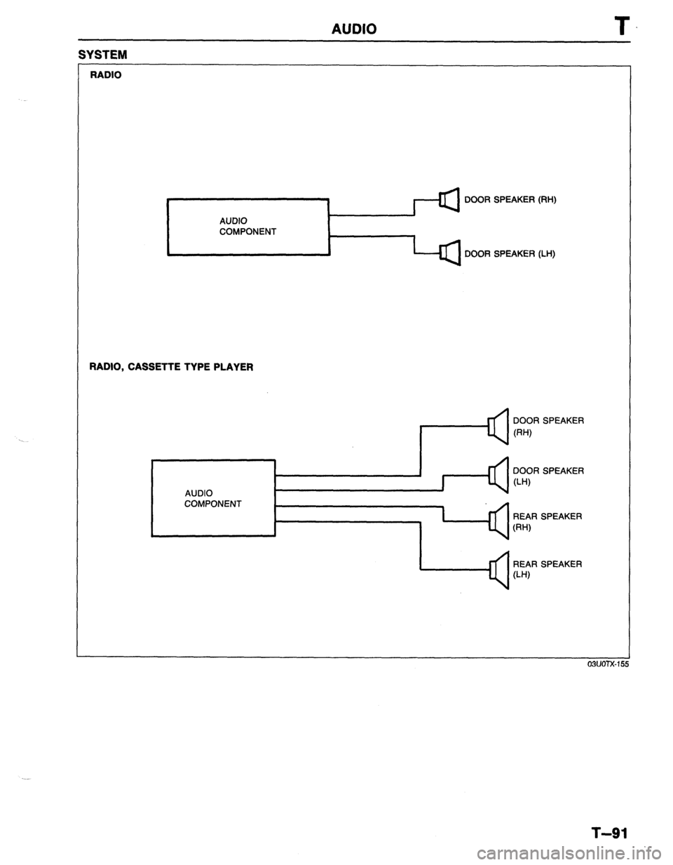
SYSTEM
RADIO
I
DOOR SPEAKER (RH)
AUDIO
COMPONENT
.
DOOR SPEAKER (LH)
RADIO, CASSETTE TYPE PLAYER
AUDIO DOOR SPEAKER
0-W
COMPONENT
I ’ REAR SPEAKER
W-U
1 Q r SPEAKER
T-91
Page 948 of 1164
T AUDIO
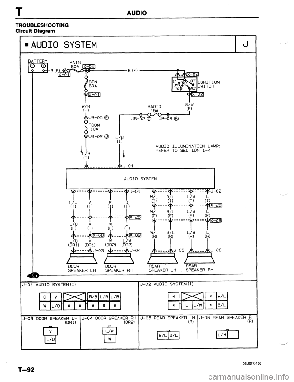
TROUBLESHOOTING
Circuit Diagram
l AUDIO SYSTEM J
AUDIO ILLUMINATION LAMP:
REFER TO SECTION I-4
AUDIO SYSTEM
I-01 AUDIO SYSTEM(I) J-02 AUDIO SYSTEM (I)
R/B L/R L/B
-03 DOOR SPEAKGlRL~ J-04 DOOR SPEAK:;R;i J-05 REAR SPEAKER(ky J-06 REAR SPEAKER$
OWOTX-156
T-92
Page 949 of 1164
AUDIO
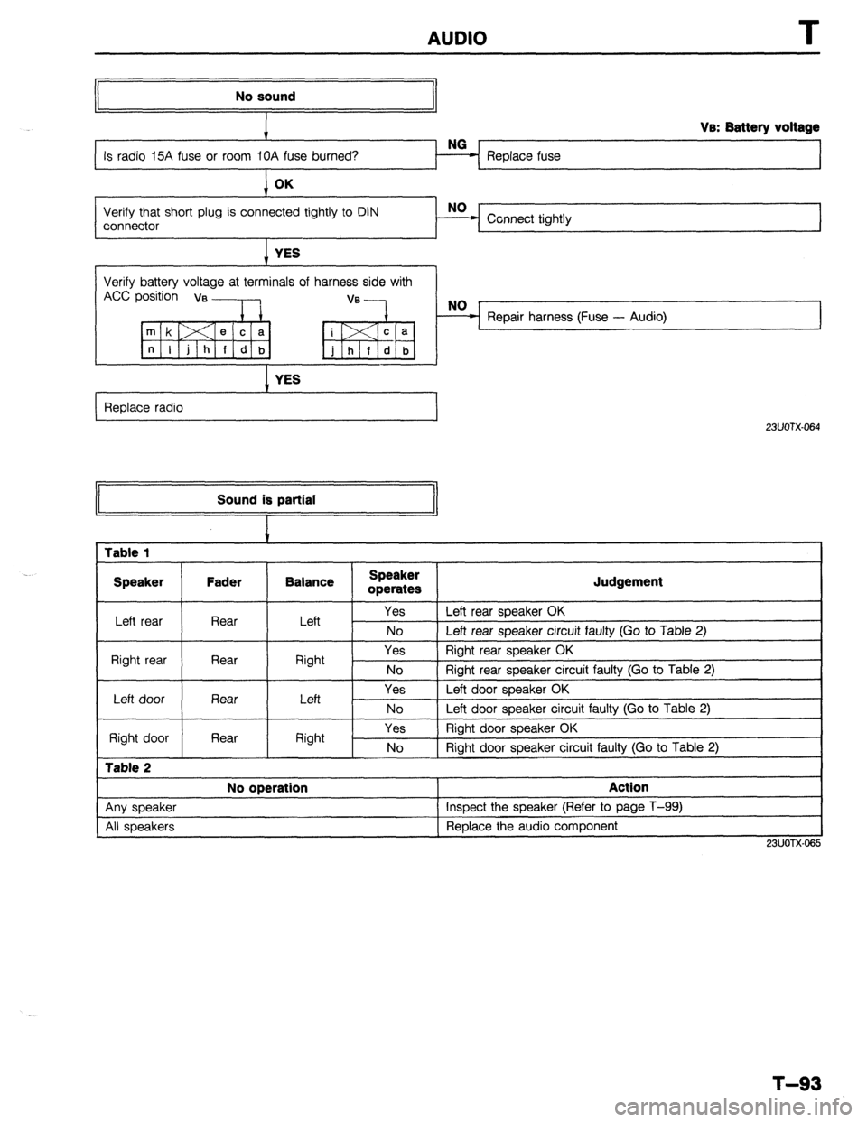
No sound
Replace fuse Va: Battery voltage
Verify that short plug is connected tightly to DIN
connector Connect tightly
I YES
Verify battery voltage at terminals of harness side with
Accp;;;ia, ,:---lb, “‘-k,
I YES
Replace radio
I
23UOTX-064 Sound is partial
1 Table 1
I Speaker Fader Balance
I Speaker
operates
I Judgement
Left rear Rear I Left Yes 1 Left rear speaker OK
No 1 Left rear soeaker circuit faulty (Go to Table 2)
Right rear Rear
I Right Yes Right rear speaker OK
No 1 Riaht rear sneaker circuit fauftv (Go to Table 2)
I
Left door
Right door
Table 2
Rear
Rear Left
Right Yes
No
Yes
No Left door speaker OK
Left door speaker circuit faulty (Go to Table 2)
Right door speaker OK
Right door speaker circuit faulty (Go to Table 2)
I No operation
I Action
I
1 Anv sneaker 1 Insoect the speaker (Refer to page T-99)
I
All speakers Replace the audio component
I
23UOTX.065
T-93
Page 950 of 1164
I
AUDIO
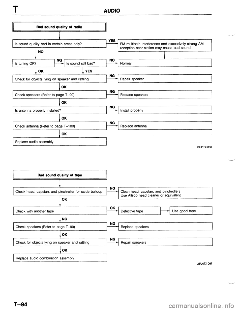
Bad sound quallty of radio
I
Is sound quality bad in certai
NO FM multipath interference and excessively strong AM
reception near station may cause bad sound
I
Is tuning OK?
I Normal t
Check for objects lying on speaker and rattling
I Repair speaker
1 OK
Check speakers (Refer to pa Replace speakers
1 OK
Is antenna properly installed?
I Install properly NO
Check antenna (Refer to page T-100) - Replace antenna L I L I OK
Replace audio assembly
23UOTX-066
II Bad sound quality of tape
II
Check with another tape Defective tape Use good tape
1 NG
Check speakers (Refer to page T-99)
I
Check for objects lying on speaker and rattling OK
I
I
Replace audio combination assembly
23UOTX.067
T-94
Trending: service interval, service, remote control, warning lights, towing, tow bar, power steering fluid
