brake MAZDA 323 1992 Suplement User Guide
[x] Cancel search | Manufacturer: MAZDA, Model Year: 1992, Model line: 323, Model: MAZDA 323 1992Pages: 279, PDF Size: 24.15 MB
Page 99 of 279

FRONT AXLE M
13EOMX308
13EOMX-310
1
13EOMX-311
Removal note
Locknut
Caution
l Do not damage the drive shaft.
l Do not reuse the locknut.
1.
Raise the staked portion of the locknut using a chisel.
2. Lock the
hub by applying the brakes.
3. Remove the locknut.
Tie rod end
Caution i
l Do not damage the dust boot.
t
Losen the nut and disconnect the tie rod end bv using the
I
SST.
P
Installation note
Tie rod end
Caution
l Do not damage the dust boot.
tnstall the nut and secure it with the new cotter
Tightening torque:
43-56 N-m (4.3-5.8 kgf,m, 31-41 ft-lbf
Locknut
lnstail a new
locknut and stake it, as shown. pin.
Tightening torque: 236-318 N-m
f 24.0-32.5 kgfm, 174-235 ftelbf ]
M-7.
Page 104 of 279

REAR AXLE
WHEEL HUB, KNUCKLE
Removal I Inspection / installation
1. Remove in the order shown in the figure, referring to
Removal Note. 2. Inspect all parts and repair or replace as necessary.
3. Install in the reverse order of removal, referring to Installation Note.
Caution
l Loosely tighten the shock absorber bolts. Lower the vehicle and tighten the bolts to the specified
torque with the vehicle unladen.
4. Adiust the rear wheel alianment.
16-22 1?.6-2.3, 12-16 I
7
IO.o-13.0,
66-66.7 1 1. Wheel and tire
2. Locknut
Removal Note..; . . . . . . . . , . . . . ,.......- -.. page M-f 3
Installation Note .._...,.,...._.__........ page M-13
I$ Brake caliper assembly
Service . . . . . . . . . . . ..e......._......... ,.,...,....
Section P
4. Disc plate
‘Service ..I....................__....... . . . . . . . . . Section P 5. Af3S wheel speed sensor (if equipped)
6. Wheel hub, knuckle
Disassembly I Inspect& /
Assem bty . . . . . . . ..I..........*..*.*...-... page M-14
Inspect wheel hub and knuckle for damage
or cracks
Inspect dust cover for damage or defor-
mation
M-12
Page 105 of 279

REAR AXLE M
Removal note
Locknut
Caution
l Do not damage the drive shaft.
l Do not reuse the locknut.
I. Raise the staked portion of the tocknut using a chisel.
2. Lock the hub by applying the brakes.
3. Remove the locknut.
1 13EOMX-308
13EOMX-327 installation note
Locknut
Install a new locknut and stake it, as shown.
Tightening torque: 236-318 N-m
[ 24.0-32.5 kgfm, f 74-235 ftelbf
‘I
Page 112 of 279
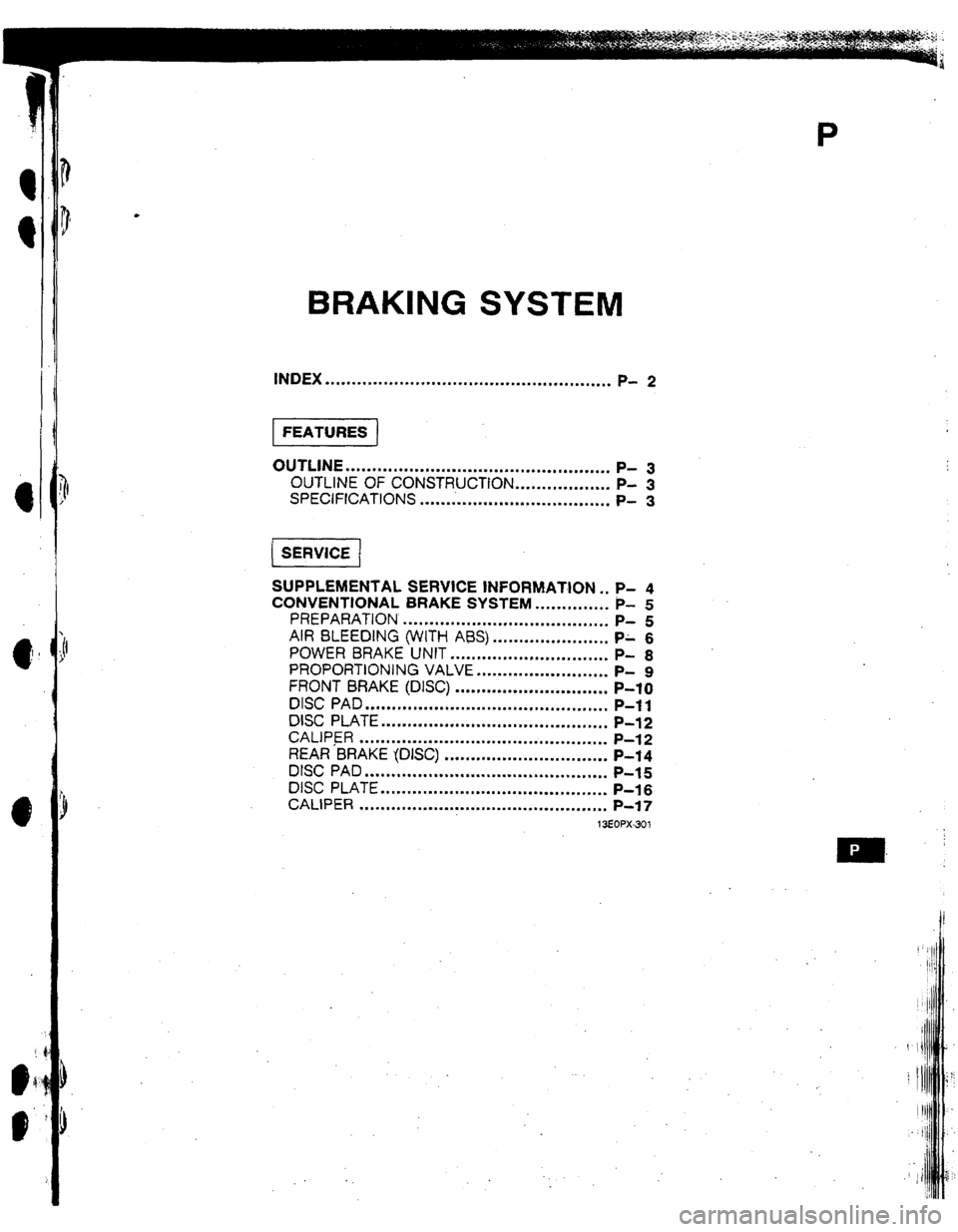
BRAKING SYSTEM
INDEX ..**.............=*..*..*....~.~............*.,.*...=.
P- 2
OUTLINE . . . . ..~....**.*...........*~...................***
1 P- 3
t il OUTLINE
OF CONSTRUCTION . . . . . . . s.e . . . .
l *..
P- 3
i SPECIFfCATIUNS
. . . . . . . . ..m...*.-..**......n.*.**...
P- 3
e , :
8 [ SERWCE /
SUPPLEMENTAL SERVICE INFORMATION s. P- 4
CONVENTIONAL BRAKE SYSTEM . . . .
l .m..m.s.m P-
5
PREPARATION
. ..* . . . . . . . . . . . . . . . . . . . l . . . . *.*..*.*..I P- 5
AIR BLEEDING (WITH ABS) . . . . . . l .* . . . . . . . . a . . . .
PA 6
POWER 8RAKE UNIT ..*.I..*....*..*....*...*..*..
P- 8
PROPORTJONING VALVE
l . . . . . . . . . . . . . . . . . l . . . . . .
P- 9
FRONT BRAKE (DISC)
. . . . ..**.*.........e.........
P-IO
DISC PAD
. . . . ..m*.m....*bL*m....*...............*......
P-l 1
DISC PLATE
..*..*..*.**..*..a.............*.-.*.....,.
P-12
CAMPER . . . ..m....I*.....*..m*..*......*......*....*...
P-l 2
REAR BRAKE (DISC)
. . . . . . . . . . . . . . . . . * . . . . . . . . l . . . . P-14
DISC PAD . . . . . . . . . . . . . . . . ..~.....................~.~...
P-l 5
DISC PLATE . . . . . . . . . . ..m.e..m....=...*...........*....
P-l 6
CALIPER . . . ..*..m.......I.......~m..~*..*.~......~...*.
P-97
13EOPX-301
Page 113 of 279
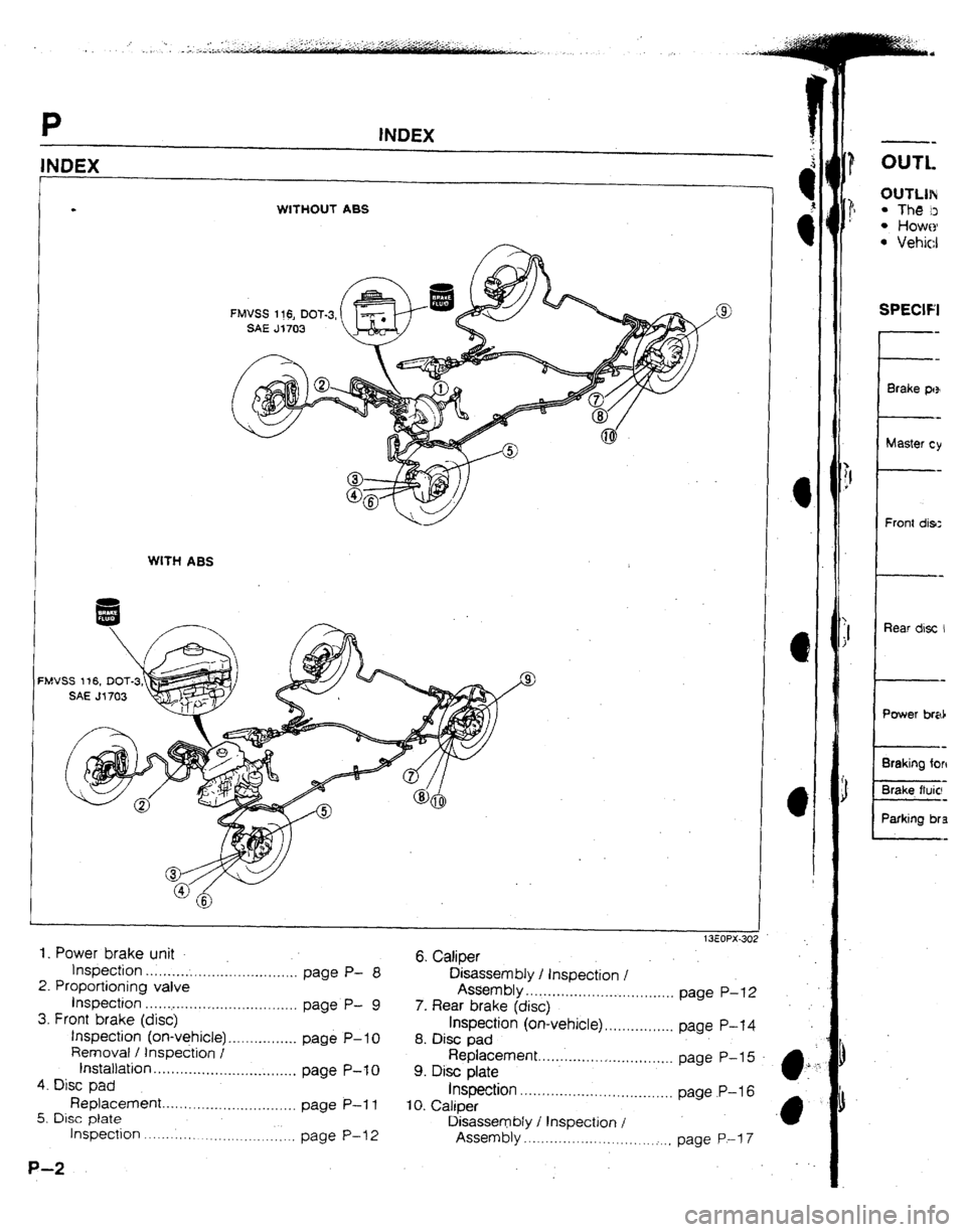
INDEX
. WfTHOUT ABS
WITH ASS
‘MVSS 1 t6, DOT-3
.
1. Power brake unit
tnspection . . . . . . . . . . . . . . . . . . . . . . . .._......... 6. Catiper
page P- 8
Disassembly / tnspection I
2. Proportioning valve
tnspection . . . . . . .._..... . . . . . . . . . . . . . . . . . . . . . Assembly
P- . . . . . . . . . . . . ..I............I.....I page P-12
9
3. Front brake (disc) page
7. Rear brake (disc)
tnspection (on-vehicle). . . . . . . . . . . . . . . . page hspechn (on-vehicle) . . . . . . . . . . . . . . . . page P-l 4
P- IO
Removai / tnspection I 8. Disc pad t nstattation Replacement
page P-to 9. Disc plate ............I..r.... 1 . . . . . . . ~_. page P-15 .
. ..t..I...-.......-..l.._*.......
4. Disc pad
Replacem& Inspection . . . . . , . . . . . .
. . . . . ..a. ..I......,,,..
. . ..I.....-............-...,...
5. Disc piate page P-11
IO. Caliper page P-16
Inspection . . . . . . ._. ._. ._. __. . . ._. page P-l 2 Disassembly I t nspection I
Assembly . . . . . . ..I........................I page P-l 7
P-2 --
OUTL OlJTLlN
l The D
l HOWO
l Vehicl SPECIFI
Front dis:
Rear disc I
Braking for4
Brake. fluic:
Parking bra
Page 114 of 279

OUTLlNE P
OUTLfNE
OUTLINE OF CONSTRUCTION
l The brake system remains similar to that of the previous model. l However, because all new models use a higher-horsepower engine, the brake system is enlarged as a whole.
l Vehicles without ABS use a portless-type master cylinder
13EOPX-303
SPECIFICATIONS
Brake pedal
Master cylinder
Front drsc brake
Rear disc brake
Power brake unit
Braking force control device
Brake fluid
Parking brake Item Specification
Type Suspended
I
PedaJ lever ratio 4.1
Max. stroke mm [in] 140 j5.511
I,
Type Tandem
Cylinder inner diameter mm {in] Without ABS: 25.4 j 1 .UO ]
With ABS: 23.8 to.941 3-
Type Ventilated disc ?
Cylinder bore mm [in)
57.2 12.253
Pad dimensions (area x thickness)
mm2 {rn2) xmm [In) 5,200 (8.OSl x 10 (0.39)
Disc plate dimensions mm (in]
(outer diameter x thickness) 274x24 (10.79x0.94)
Type Solid disc
Cylinder bore mm Jon]
34.9 j 1.37 ]
Pad dimensions (area x thrckness)
mm’ (in21 xmm [in) 3,200 I4.961 x8 (0.31)
DISC plate dimensions mm t,n]
(outer diameter x thickness) 280x10 (tl.02xu.39]
il
Type Without ABS: Vacuum multIplier
With ABS: Hydraulrc muttiplier
Diameter mm Iln]
(without ABS) 188.4 17.42) +215.2 t8.47)
We Without ABS: Dual proportioning valve
With ASS: Proportioning valve
FMVSS 116, DOT-3, SAE J1703
Mechanical twGrear-wheel control
Type
Operation system Center lever
13EOPX.304 t
Page 115 of 279
P SUPPLEMENTAL SERVICE INFORMATION I
. .
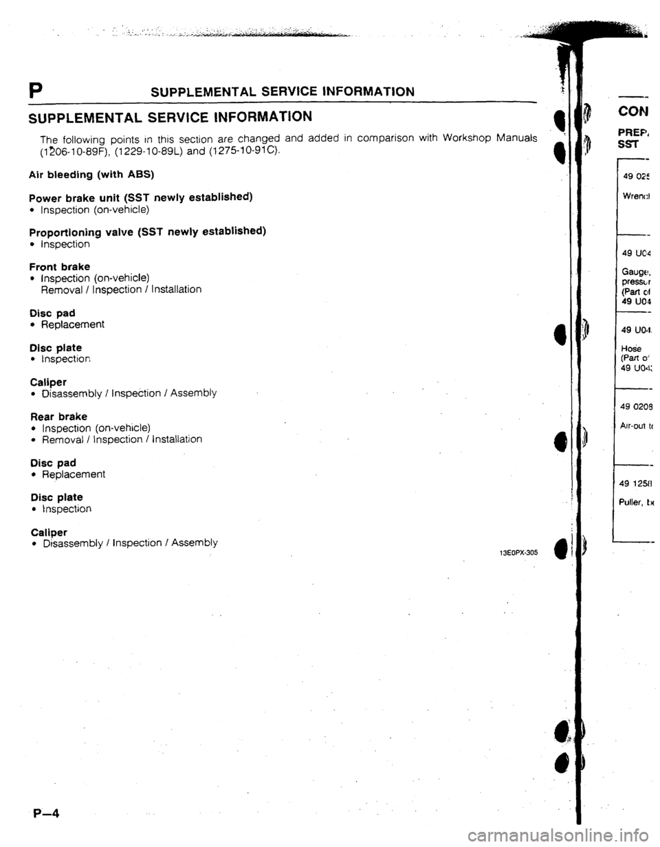
SUPPLEMENTAL SERVICE
INFORMATION
The following points in this section are changed and added in comparison with Workshop Manuals
(1206-I 0-89F), (I 229-I 0-89L) and (12751 O-91 c).
Air bleeding (with ABS)
Power brake unit (SST newly established)
l Inspection (on-vehicte)
Proportioning valve (SST newly established)
l Inspection
Front brake
l Inspection (on-vehicle)
Removai I Inspection / Installation
Disc pad
l Replacement
Disc plate
l Inspection
Caliper
l Disassembly I Inspection I Assembly
Rear brake
l Inspection (on-vehicle)
l Removal i Inspection I Installation
Disc pad
l Replacement 4
Disc plate
l Inspection
Caliper
l Disassembly I Inspection I Assembly 13EOPX-305
4
P-4
CON
PREP,
SST
Pm
49
ue4
Gauge, pressL r
(Part d
49 um
Pa
49 uw
HOti (Part 0;
49 uu4;
49 1258
Duiler, LH
Page 116 of 279

I :
;!
i
I
I
CONVENTIONAL BRAKE SYSTEM P
CONVENTIONAL BRAKE SYSTEM
PREPARATION
SST
49 0259 770B
Wrench, fiare nut For
removal and 49 U043 OAO
Gauge set, oil
pressure For
Inspectron of
brake fluId
pressure
49 uo43 004
Gauge, oil
pressure
{Part 04
49 U043 OAO) For
inspection of
brake fluid
pressure 49 UO43 005
Joint
(Part of
49 UO43 OAO) For
inspection of
brake fluid
o pressure
49 0208 70tA
Air-out tool, boot For
removal of
piston seal 49 FAf8 602
Wrench, disc
brake piston For
removal and
installat!on of disc
call per piston
49 1258 071
Puller, bearing For 49 0221 600C
removal of caliper
a-- E;.;d tool, disc needle bearing For
installation of
brake pads
Page 117 of 279
P CONVENTIONAL BRAKE SYSTEM
93GOW74:
13EOPX-307
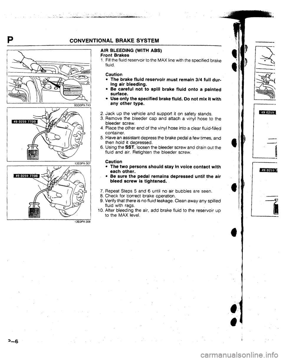
AIR BLEEDlNG (WITH ABS)
Front Brakes
1. Fill the fluid reservoir to the MAX line with the specified brake
fluid.
Caution
l The brake fluid reservoir must remain 3/4 full dur-
ing air bleeding.
l Be careful not to spill brake fluid onto a painted
surface.
l Use only the specified brake fluid. Do not mix it with
any other type.
2. Jack up the vehicle and support it on safety stands.
3. Remove the bleeder cap and attach a vinyl hose to the
bleeder screw.
4. PIace the other end of the vinyl hose into a clear fluid-filled
container.
5. Have an assistant depress the brake pedal a few times, and
then hold it depressed.
6. Using the SST, loosen the bleeder screw and drain out the
fluid and air. Retighten the bleeder screw.
Caution
l The two persons should stay in voice contact with
each other.
l Be sure the pedal remains depressed until the air
bleed screw is tightened.
7. Repeat Steps 5 and 6 until no air bubbles are seen.
8. Check for ‘correct brake operation.
9. Verify that there is no fluid leakage. Clean away any spilled
fluid with rags.
IO. After bleeding the air, add brake fluid to the reservoir up
to the MAX level.
Page 118 of 279
CONVENTlONAL BRAKE SYSTEM P
13EOPX-309
f3EOPX-310
13EOPX-311
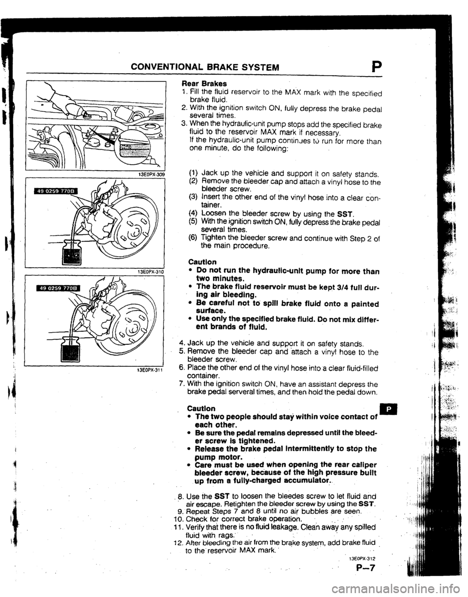
Rear Brakes
1. Fill the fluid reservoir to the MAX mark with the specified
brake fluid.
2. With the ignition switch ON, fully depress the brake pedal
several times.
3. When the hydraulic-unit pump stops add the specified brake
fluid to the reservoir MAX mark if necessary,
If the hydraulic-unit pump coniinJes tti run for more than
one minute, do the following:
(1) Jack up the vehicle and support it on safety stands.
(2) Remove the bleeder cap and attach a vinyl hose to the
bleeder screw.
(3) Insert the other end of the vinyl hose into a clear con-
tainer.
(4) Loosen the bleeder screw by using the SST.
(5) With the ignition switch ON, fully depress the brake pedal
several times.
(6) Tighten the bleeder screw and continue with Step 2 of
the main procedure.
Cautfon
l Do not run the hydraulic-unit pump for more than
two minutes.
l The brake fluid reservoir must be kept 3/4 fult dur-
ing air bleeding.
l 8e careful not tb spill brake fluid onto a painted
surface.
l Use only the specified brake fluid. Do not mix differ-
ent brands of fluid.
4. Jack up the vehicle and support it on safety stands.
5. Remove the bleeder cap and -attach a vinyl hose to the
bleeder screw I
6, Place the other end of the vinyl hose into a clear fluid-filled
container.
7. With the ignition switch ON, have an assistant depress the
brake pedal serveral times, and then hold the pedal down.
Caution .
l The two people should sta)i within voice contact of u
each other.
l Be sure the pedal remains depressed until the bleed-
er screw is tightened.
l Release the brake pedal intermittently to stdp the
pump motor.
l Care must be used when opening the rear caliper
bleeder screw, because of the.high pressure buift
up from a fully-charged accumulator..
9. Use the SST to loosen the bleedes screw to let fluid and
air e-ape. Retighten the bleeder screw by using the SST.
9. Repeat Steps 7 and 8 until no ai! bubbles are seen.
IO. Check for correct brake operation. .
11 l Verify thai there is no fluid feakage. Clean aw& any spilled
flu@ with rags.’ .
f 2. After bleeding the air from the brqke system, add brake fluid _
to the reservoir MAX mark. . -
13EOPX-3 12
,: .
P-7