diagram MAZDA 323 1992 Suplement User Guide
[x] Cancel search | Manufacturer: MAZDA, Model Year: 1992, Model line: 323, Model: MAZDA 323 1992Pages: 279, PDF Size: 24.15 MB
Page 185 of 279
GI Reading Wiring Diagrams
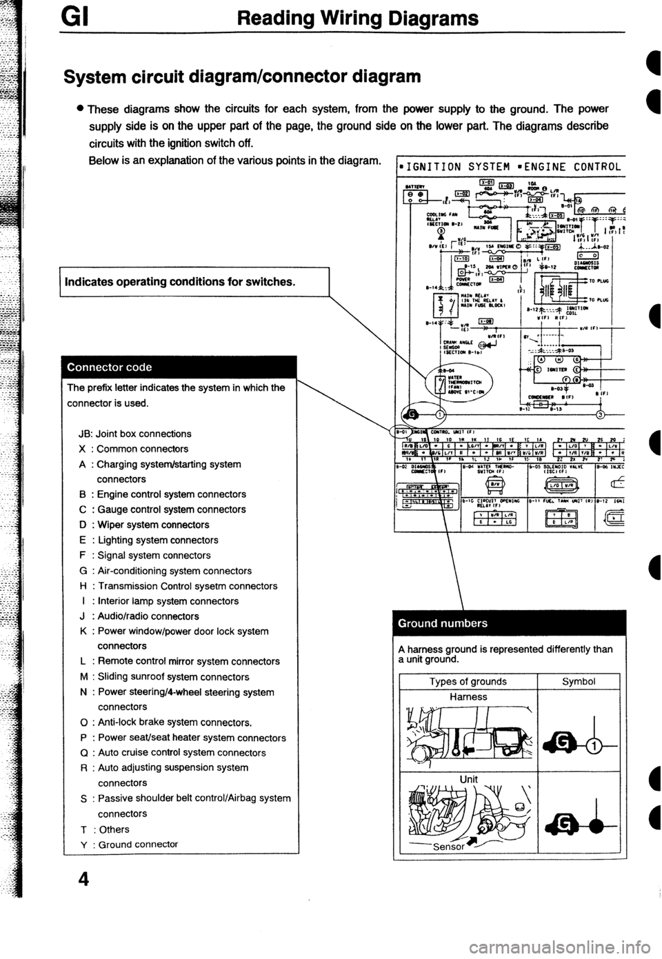
System circuit diagram/connector diagram
l These diagrams show the circuits for each system, from the power supply to the ground. The power
supply side is on the upper part of the page, the ground side on the lower part. The diagrams describe
circuits with the ignition switch off. Below is an explanation of the various points in the diagram.
I Indicates operating conditions for switches.
I
The prefix letter indicates the system in which the
:onnector is used.
JB: Joint box connections
X : Common connectors
A : Charging system/starting system
connectors
B : Engine control system connectors
C : Gauge control system connectors
D : Wiper system connectors
E : Lighting system connectors
F : Signal system connectors
G : Air-conditioning system connectors
l-l : Transmission Control sysetm connectors
I : Interior lamp system connectors
J : Audio/radio connectors
K : Power window/power door lock system
connectors
L : Remote control mirror system connectors
M : Sliding sunroof system connectors
N : Power steering/4-wheel steering system
connectors
0 : Anti-lock brake system connectors.
P : Power seat/seat heater system connectors
Q : Auto cruise control system connectors
R : Auto adjusting suspension system
connectors
S : Passive shoulder belt control/Airbag system
connectors
T : Others
Y : Ground connector
4
IGNITION SYSTEM mENGINE CONTROL
A harness ground is represented differently than
a unit ground.
Types of grounds
Harness
Unit Symbol
Page 186 of 279
k
Reading Wiring Diagrams GI
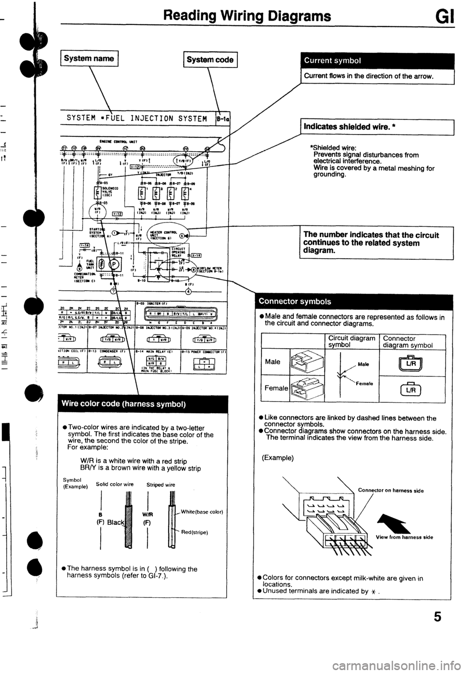
SYSTEM =F\UEL INJECTION SYSTEM i-1 Indicates shielded wire. *
I
*Shielded wire:
Prevents signal disturbances from
electrical interference.
Wire is covered by a metal meshing for
grounding. . Current flows in the direction of the arrow. t
l Two-color wires are indicated by a two-letter
symbol. The first indicates the base color of the
wire, the second the color of the stripe.
For example:
W/R is a white wire with a red strip
BR/Y is a brown wire with a yellow strip
Symbol
(Example) Soled color wire Striped wire
White(base color)
Red(stripe)
l
The harness symbol is in ( ) following the
harness symbols (refer to GI-7.).
T L The number indicates that the circuit
continues to the related system
l Male and female connectors are represented as follows in
the circuit and connector diagrams.
CirZirb~ldiagram Connector
diagram symbol
Mata
l Like connectors are linked by dashed lines between the
connector symbols.
@Connector diagrams show connectors on the harness side.
The terminal indicates the view from the harness side.
(Example)
Connector on harness side *
View horn herness side
0 Colors for connectors except milk-white are given in
locations.
a Unused terminals are indicated by x
Page 187 of 279
GI Reading Wiring Diagrams
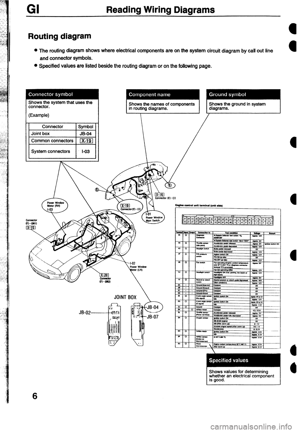
Routing diagram
l The routing diagram shows where electrical components are on the system circuit diagram by call out line
and connector symbols.
l Specified values are listed beside the routing diagram or on the following page.
Shows the names of components in routing diagrams. Shows the ground in system
diagrams. JOINT B
Shows values for determining
whether an electrical component
is good.
6
Page 188 of 279

Reading Wiring Diagrams GI
HARNESS SYMBOLS
DESCRIPTION OF HARNESS
FRONT HARNESS
ENGINE HARNESS
INSTRUMENT PANEL HARNESS
REARHARNESS
REAR NO.2 HARNESS
REAR NO.3 HARNESS SYMBOL
F) TTT
E) m
(1) %4l
(W
VW m
(R3) DESCRIPTION OF HARNESS
EMISSION HARNESS
INJECTOR HARNESS
INTERIOR LAMP HARNESS
FLOOR HARNESS
DOOR NO.1 HARNESS
DOOR NO.2 HARNESS
NSTRUMEN\T\PANEL HARNESS (I)
FROM; HARNESS(F) SYMBOL
INTERIOR LAMP HARNESS (IN)
Page 189 of 279

GI Reading Wiring Diagrams
Symbols
Symbol Meaning Symbol Meaning
Battery
l Generates electricity through
Resistance 0 A resistor with a constant value.
chemical reaction. l Mainly used to protect electrical
l Supplies direct current to circuits. components in circuits by maintaining
rated voltage.
l Reading resistance values.
Ground (1)
l Connecting point to vehicle body or No.1 color band other ground wire where current flows No.2 color band
-A-
from positive to negative terminal of No.3 mbr band
battery. No.4 color band
1 l Ground (1) indicates a ground point to
body through wire harness.
Ground (2)
l Gound (2) indicates point where
component is grounded directly to
body.
Remarks
l Current will not flow through a circuit if
ground is faulty.
Fuse (1)
0 Melts when current flow exceeds that
specified for circuit, interrupts current
I__q/y)__ now.
Precautions
(box)
l Do not replace with fuses exceeding
Fuse (2) specified capacity.
(Cartridge)
Main fuse/Fusible
Transistor (1)
l Electrical switching component. l Turns on when voltage is applied to Motor
0 Converts electrical energy into
mechanical energy.
Transistor (2)
0 Reading code. a Pulls in and discharges gases and
liquids.
Number of temtinak
Lamp l Emits light and generates heat when Current flows through filament. Cigarette lighter l Electrical coil that generates heat.
Page 190 of 279

-
Reading Wiring Diagrams GI
Symbol
Horn Meaning l Generates sound when current flows. Symbol Switch (1) Meaning l Allows or breaks current flow by
opening and closing circuits.
Speaker
ccl
Heater l Generates heat when current flows. Normally open (NO)
Switch (2)
I
Normally closed (NC)
Harness l Unconnected intersecting harness.
Speed sensor
+ Movement of magnet in speedometer
turns contact within sensor on and off. (Not connected)
w Connected intersecting harness.
Ignition switch
l Turning ignition key switches circuit to
operate various component.
(Connected)
Relay (1)
l Current flowing through coil produces electromagnetic force causing contact to open or close.
No current to coil Current to coil
Uormally open (NO)
Relay (2) Normally open relay (NO)
lormally closed (NC) [/I jr No flow @jj 1 Flow
Normally closed relay (NC)
Sensor (variable) a Resistance changes with other Diode l Known as a semiconductor rectifier,
components operation. the diode allows current flow in one
IA direction only.
R
CaIhode(K)--++- Anode(A)
- Flow 01 electric C”llO”,
KIIZT)-A K-A K-A
#ensor (thermistor) 0 Resistance changes with temperature. Light-emitting diode l A diode that lights when current flows.
V-ED) l Unlike ordinary bulbs, the diode does
not generate heat when it.
%u
I-
- Cathode(K) -$----- Anode(A)
Capacitor
l Component that temporarily stores
electrical charge.
----it----
Flow of current
Solenoid
l Current flowing through coil generates Reference diode l AIIOWS current to flow in one direction
electromagnetic force to operate (Zener diode) up to a certain voltage; allows current
to flow in the other direction once that
ti
n voltage is exceeded.
9
Page 191 of 279
Reading Wiring Diagrams
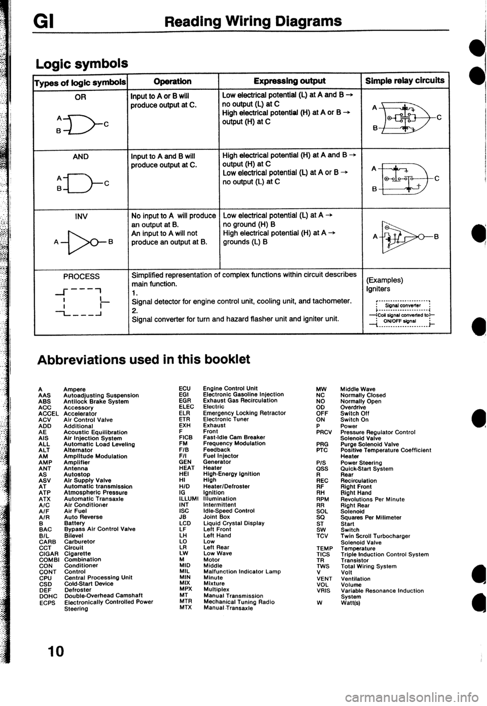
Loaic symbols I
ypes of logic symbols Operation Expressing output Simple relay circuits
OR
Input to A or 8 will Low electricai potential (L) at A and B +
produce output at C. no output (L) at C
A
6
D- High electrical potential (H) at A or B +
C output (H) at C
AND Input to A and B will High electrical potential (H) at A and B +
produce output at C. output(H) at C
q---J-c
Low electrical potential (L) at A or B + A
no output (L) at C
B a-00-a C
6
INV No input to A will produce Low electrical potential (L) at A -+
an output at B. no ground (H) B
An input to A will not High electrical potential (H) at A +
A- 6 produce an output at B. grounds (L) B A- 6
PROCESS Simplified representation of complex functions within circuit describes
main function. (Examples)
---
--I- 1 1. Igniters
I
-L-l Signal detector for engine control unit, cooling unit, and tachometer.
Ii- 2. r”~“-‘-‘-““‘~~‘.“’
Sbnsl conwflw :
i...-..--.---......-.~~
Signal converter for turn and hazard flasher unit and igniter unit.
Abbreviations used in this booklet
A
AAS
ABS
ACC
ACCEL
ACV
ADD
AE
AIS
ALL
ALT
EP
ANT
EV
EP
ATX
A/C
AIF
AIR
:AC
B/L
CARB
CCT
CIGAR
COMBI
CON
CONT
CPU
CSD
DEF
DOHC
ECPS Ampere
Autoadjusting Suspension
Antilock Brake System
Accessory
Accelerator
Air Control Valve
Additional
Acoustic Equilibration
Air Injection System
Automatic Load Leveling
Alternator
Amplitude Modulation
Amplifier
Antenna
Autostop
Alr Supply Valve
Automatic transmission
Atmospheric Pressure
Automatic Transaxle
Air Conditioner
Air Fuel
Auto Reverse
Battery
Bypass Air Control Valve
Bilevel
$rr$:,tor
Cigarette
Combination
Conditioner
Control
Central Procassino Unit
&Id-Start Device -
Defroster
Double-Overhead Camshaft
Electronically Controlled Power
Steering ECU
EGI
EGR
ELEC
ELR
ETR
EXH
E
FICB
FM
F/S
F/I
GEN
ET
HI
H/D
I;LUMl
INT
ISC
JB
LCD
LF
k!
z Engine Control Unit
Electronic Gasoline Injection
Exhaust Gas Recirculation
Electrio
Emergency Locking Retractor
Electronic Tuner
Exhaust
Front
Fast-Idle Cam Breaker
Frequency Modulation
Feedback
Fuel lniector
Generator
Heater
High-Energy Ignition
High
Heater/Defroster
Ignition
lllumlnation
Idle-Speed Control
Joint Box
Liquid Crystal Display
Left Front
Left Hand
Low
Left Rear
Low Wave
:I, Motor
Middle
MIL
MIN Malfunction Indicator Lamp
Minute
MIX
Mixture
MPX Multiplex
ZR Manual Transmission
MTX Mechanical Tuning Radio
Manual .Transaxie PRG
PTC
P/S ass
kc
FIF
. . .
RH
RPM
!2EL
SQ
ST
SW
TCV
TEMP
TICS
TR
TWS
V
VENT
VOL
VRIS
W Middle Wave
Normally Closed
Normally Open
Overdrive
Switch Off
Switch On
Power
Pressure Regulator Control
Solenoid Valve
Purge Solenoid Valve
Positive Temperature Coefficient
Heater
Power Steering
;im&k-Start System
Recirculation
Right Front
Right Hand
Revolutions Per Minute
Right Rear
Solenoid
Squares Per Milimeter
Start
Switch
Twin Scroll Turbocharger
Solenoid Valve
Temperature
Triple Induction Control System
Transistor
Total Wiring System
Volt
Ventilation
Volume
Variable Resonance Induction
System
Watt(s)
IO
Page 204 of 279
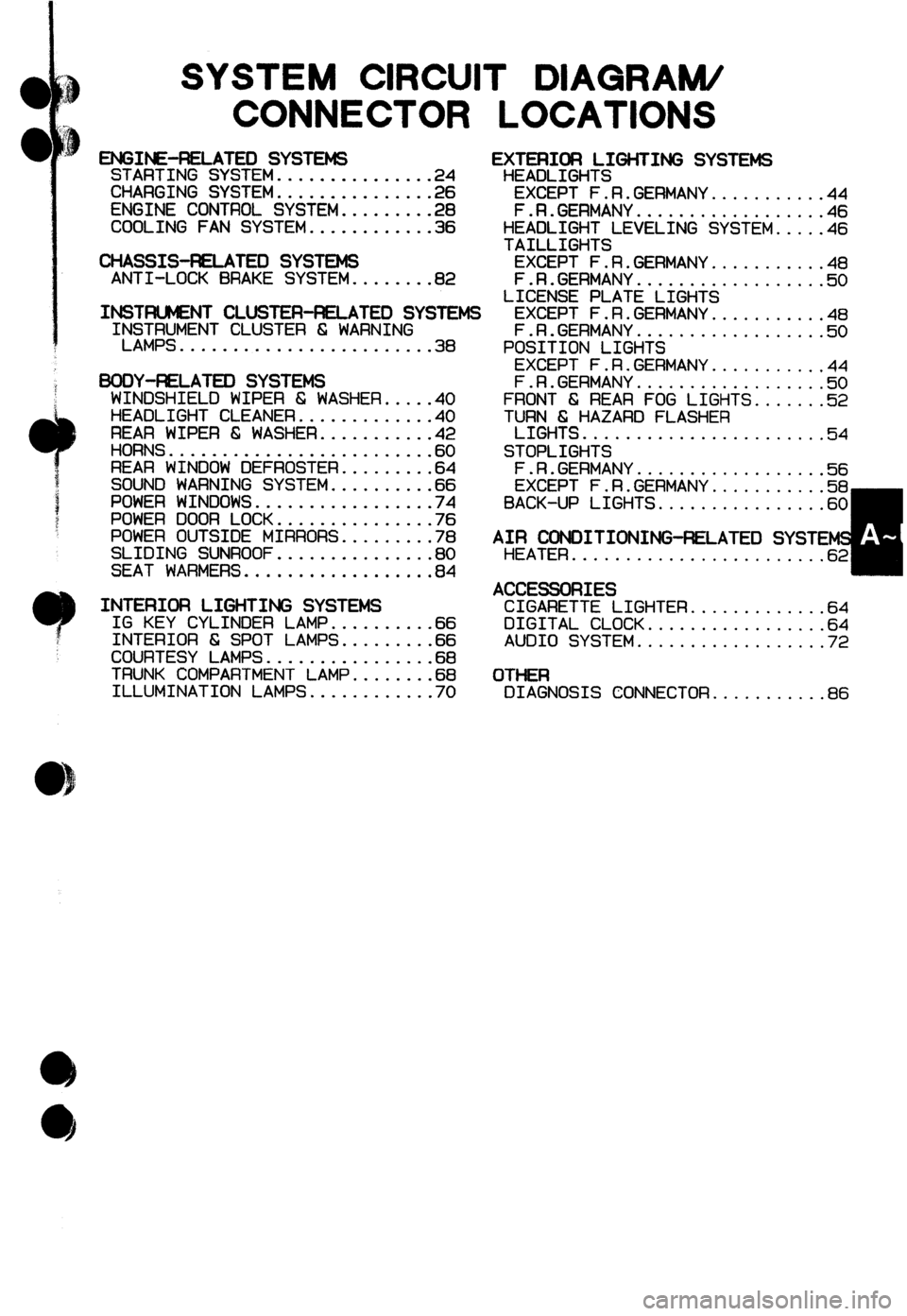
SYSTEM CIRCUIT DIAGRAM/
CONNECTOR LOCATIONS
ENGINE-RELATED SYSTEMS EXTEFlIOFl LIGHTING SYSTEMS STARTING SYSTEM...............24 HEADLIGHTS
CHARGING SYSTEM...............26 EXCEPT F.R.GERMANY...........44
ENGINE CONTROL SYSTEM.........28 F.R.GERMANY..................46
COOLING FAN SYSTEM............36 HEADLIGHT LEVELING SYSTEM.....46
TAILLIGHTS
CHASSIS-RELATED SYSTEMS EXCEPT F.R.GERMANY...........48
ANTI-LOCK BRAKE SYSTEM........82 F.R.GERMANY.a................50
LICENSE PLATE LIGHTS
INSTFUMENT CLUSTEA-FiELATED SYSTEMS EXCEPT F.R.GERMANY...........48
INSTRUMENT CLUSTER 6 WARNING
I LAMPS........................38
BOOY-ELATED SYSTEMS WINDSHIELD WIPER 6 WASHER.....40
HEADLIGHT CLEANER.............40
REAR WIPER 6; WASHER...........42
HORNS.........................6 0
REAR WINDOW DEFROSTER.........6 4
SOUND WARNING SYSTEM..........6 6
POWER WINDOWS.................7 4
POWER DOOR LOCK...............7 6
POWER OUTSIDE MIRRORS.........7 8
SLIDING SUNROOF...............8 0
SEAT WARMERS..................8 4 F.R.GERMANY..............u.i5 ii
POSITION LIGHTS
EXCEPT F.R.GERMANY...........4 4
F.R.GERMANY..................5 0
FRONT 6 REAR FOG LIGHTS.......5 2
T;l%&HAZARD FLASHER
sTopLIGHi ..... ...............
.54
F.R.GERMANY..................5 6
EXCEPT F.R.GERMANY...........5 8
BACK-UP LIGHTS................6 0
INTERIDFI LIGHTING SYSTEMS IG KEY CYLINDER LAMP..........6 6
INTERIOR 6; SPOT LAMPS.........6 6
COURTESY LAMPS................6 8
TRUNK COMPARTMENT LAMP........6 8
ILLUMINATION LAMPS............7 0
A;~ATOEOS;DITIONING~LATED SYSTE
........................
ACCESSORIES
CIGARETTE LIGHTER.............64
DIGITAL CLOCK.................6 4
AUDIO SYSTEM..................7 2
OTHER
DIAGNOSIS CONNECTOR...........86
Page 274 of 279
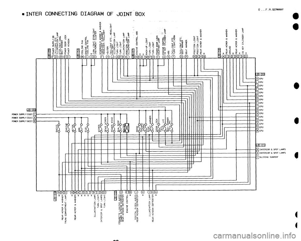
aINTER CONNECTING DIAGRAM OF JOINT Box
0 _. .F.R.GEWANY
0
0
II IIIIIIll’ i D J CPU
CPU
CPU
CPU
CPU
cw
CPU
,
1 I I I I I
11 I I I
II I II 1 I I I-
I II I I IT
I'
I
I I I I
1 II I I II I f I II I I II
I I , 1
I
92