ignition MAZDA 323 1992 Suplement Owner's Manual
[x] Cancel search | Manufacturer: MAZDA, Model Year: 1992, Model line: 323, Model: MAZDA 323 1992Pages: 279, PDF Size: 24.15 MB
Page 75 of 279

F3 FUEL SYSTEM
13EOt=3-349
f3EOF3-350
0
0
ECU
G
0
0 i
13EOF3-35
tNJECTOR
t nspection
injector resistance
1. Disconnect the injector harness,
2. Measure resistance of the injector.
Resistance: l-3Q (at 20°C (68*F])
3. If
not as specified, replace the injector.
Volume Test
1, Remove the injectors and delivery pipe assembly with the
conectors con netted.
2. Affix the injectors to the delivery pipe by using wire.
Warning
l Be extremely careful when working with fuet. Al-
ways work away from sparks and open flames.
Caution
l Affix the injectors firmly to the detivery pipe so that
they do not move.
3. Turn the ignition switch ON and ground the F/P terminal
of the diagnosis connector.
4. Test the individual injectors by following the procedure out-
lined in the chart below.
Test inpctor no.
1
2
3
4 Disconnect injector connector no. Ground ECU terminal
3 2u
4 2v
1 2U
2 2v 5. Check the injection volume by using a graduated container.
Injection v&tie:
105-151 cc [6.40-9.22 cu in)/15 sec.
6. If the injection volume is not as specified, replace the injector.
INJECTOR REStSTOR
Inspection
I. Disconnect the injector harness.
?. Measure resistance of the injector resistor.. .
tnjector
No.1
No.2
No.3
No.4 Measured terminals
Resistance
gg 6 0 (at 2U°C
16PF))
3. If not as specified, replace ihe injector resistor.
F3-42 _
13EOF3-352
Page 79 of 279

F3 CONTROL SYSTEM
Terminal voltage
Reference date
Vs: Battery voltage
‘em&al Input Output Connected to Test condition Correct voltage Remark
1A - - Battery Constant VB
For backup
18 0 Main relay
Ignition switch OFF ov
(FUEL INJ relay) -
ON
V8
1C 0 lgnitlon switch While cranking Approx. 1 OV
(START) -
Ignition switch ON ov
10 0 Self-Diagnosis Test switch at SELF TEST
Wtth Self-
Checker Lamp illuminated for 3 sec. after ignition Approx. 5V
(monitor lamp) switch OFFdON Diagnosis Check-
er and System
lamp not iltuminated after 3 sec. V8 Selector
Test switch at 02 MONITOR with engine
idling Approx. 5V
Monitor lamp illuminated
Test switch at 02 MONITOR with engine
idling Vi3
Monitor lamp not illuminated
IE - - - - - -
IF
0 Self-Diagnosis Buzzer sounded for 3 sec. after ignition
Below 2SV
l With Seif-
Checker switch OFF-+ON
Diagnosis
(service code)
Buzzer not sounded after 3 set V0 ’ Checker and
Buzzer sounded Below 2.5V System Selector
l With System
Buzzer not sounded VB Selector test
switch at SELF
TEST
1G 0 igniter tgnition switch ON
ov
-
Idte
Approx. 0.2V
It-l 0
Solenoid valve Ignition switch ON
VB
(wastegate)
Idle
Approx. 2V ’ -
II
0 Fuel pump While cranking
Approx. 1 OV
resistor/relay -
Idle
8etow 1.5V
IJ 0 NC relay Ignition switch ON
VB
A/C switch UN at idle
Below 2.5V
. NC switch OFF at idle V3
-
IK 0 Diagnosis
connector
(TEN terminal) System Selector test switch at
02 MONITOR
System Selector test switch at
SELF TEST V0
-
8elow l*OV
1L - - - - - -
I
1M - - - - -
I -
lr ‘- l-7
f L.-
r
20 20 2M 2K 21 2G 2E 2c 2A IU 1S 10 10 ltvl tK II Ir; tE 1~ IA
1
22 2x 2v 2T ZR 2P 2N 2L 25 2H 2F 20 2B 1V IT 1R tP 1N IL 1J 1H IF 1~ 1~
1
J=3-46 --
4lways 4
--
AIways 4
--
Atways 1
--
Always 1
-a
Always ’
--
Always i
-e
Always I
2.5v
Always
Always (
-m
Always f
-a
Always 1
Always (
--
Always I
2.5V
Always 1
Always t
Always
--
Page 80 of 279

,,1
CONTROL SYSTEM F3 ‘1
Va: Battew voltage
Incorrect voltage Possible cause
Always OV
l ROOM IOA fuse burned l Open circuit In wiring from ROOM 10A fuse to ECU termina! 1A
Always OV
l Main relay malfunction l Open or short circuit in wiring from main relay to ECU terminal IB
Always OV (starter turns)
l Open or short circuit in wiring from ignition switch to ECU terminal IC
Always OV
Always VB
l Maln relay (FUEL INJ relay) malfunction l Open circuit in wiring from main relay to diagnosis connector terminal +B l Open or short circuit in wiring from diagnosis connector terminal MEN to
ECU terminal 1 D
l Poor connection at ECU connector l ECU malfunction
Always approx. 5V . ECU malfunction
Always below
2.5v
Always Ve -
-
No display on Self- * Main relay (FUEL INJ relay) malfunction
Diagnosis Checker
l Open circuit in wiring from main relay to diagnosis connector terminal + B
“88” displayed and
l Open or short clrcurt in wiring from diagnosis connector terminal FEN to
buzzer sounds con- ECU terminal tF
ti nuousl y
l Poor connection at ECU connector l ECU malfunction
Always QV
l Short circuit in wiring from igniter to ECU terminal 16
Always OV or VB
l Refer to Code No.42 Troubleshooting
(Refer to 323 4-Wheel Drtve Workshop Manual (12?9-IO-89L))
Always VB
Always OV
Always below
2.5V
Atways Ve I ’
l Fuel pump resistor/relay malfunction
l Open or short circurt in wiring from ECU terminal II to fuel pump resis-
tor/relay
A/C does not operate
l A/C reiay malfunction l Open circuit in wiring from ignition switch to A/C relay l Open circuit in wiring from A/C relay to ECU terminal 1J
A/C switch
OFF but l Short circuit in wiring from AIC relay to ECU terminal 1 J
A/C operates . ECU malfunction
l Poor connection at ECU connector l ECU malfunction
Always below 1 .OV a Short circuit in wiring from diagnosis connector terminal TEN to ECU termi-
nal 1K
Always Vs
l Open circuit In wiring from diagnosis connector terminal TEN to ECU terml-
nal IK
-
-
l Open circuit in winrig from diagnosis connector terminal GND to ground’
-
I -
.
. .
-. F3-47
Page 81 of 279

F3 CONTROL SYSTEM
Ve: Battery voltage
Termina
1N ’
10
1P
IQ
IR
IS
1T
tlJ
IV Jnput Outpul
0
0
0
0
0
0
0
0
0 Connected to
Throttle sensor
(idle switch) Test condition
Correct voltage Remark
Accelerator pedal released
Below 1.0V
lgnltlon switch
Accelerator pedal depressed
VI3 ON
Foglrght relay
P/S pressure
switch Fogtight switch ON
Fogfight switch OFF
Ignition switch ON
P/S pressure switch ON at Idle
PIS pressure switch OFF at idle Va
ov
V3
Below 1 .OV
VB -
-
A/C switch A/C switch ON
A/C switch OFF Below 23 Ignition switch
Va ’ ON and blower
motor ON
1 f Ekctrtc cooltng fan Fan operating (coolant temperature over
Below 1 .OV
switch
97OC 1207OF 1 or diagnosis connector
terminal TFA grounded) -
Fan not operating (Idle)
VI3
Blower control Blower control switch OFF or 1st position
.Va
swbtch Ignitton switch
Blower control switch 2nd or hjgher po-
Below 1 .OV ON
sition
Rear window
defroster switch Rear window defroster OFF
Rear window defroster ON Below 1 .OV Ignition switch
V0 ON
Headlight switch
Headfights ON Va
Headlights OFF -
Below 1.OV
Neutral/Clutch
Neutral position or clutch pedal
9eJow I .OV
switches
depressed
Others
Va
7
r u-.
I-I-I
f
2y 2w 2u 2s 20 20 2M 2K 21 2G 2E 2C 2A 1U 1s 10 10 1M 1K 11 rG IE tC ;A
22 2% 2V 2T 2R 2P ZN 2L 25 2H 2F 2D 28 tV 1T ‘IR IF 1N It ;J. IH IF ID 18
i
A
F3-48
-- Alwa@
Always
Always
Always
--
Always
--
Always
--
Always
--
Always
--
Always
(electric
--
Alway<;
--
Always
-e
Afway?;
I .ov
Always
--
Always
--
Alway:;
--
Page 83 of 279

F3 CONTROL SYSTEM
Vs: Battery voltage
‘erminat Input Output Connected to Test condition
Correct voltage Remark
2A’ - - Ground (i nlector) Constant CIV -
26 - - Ground (output) Constant ov -
2C - - Ground (CPU) Constant ov -
2D - - Ground (input) Constant ov -
2E 0 Distributor Ignition switch ON QV or 5v
{NE-slgnal) -
f
r ldte
Approx. 2V
2F - - - -
- -
2G 0 Dstributor Ignition switch ON
ov or 5v
(G signal)
ldte Approx. 1.5V
a-l -I- - -
- -
21 - - - - - -
23 0 Knock control unit Idle Approx. 4.W -
I
2K 0 Throttle sensor/ Constant 4.5--5SV
Airflow meter
-
2L cl
2M 0 Speedometor
sensor
Throttle sensor Ignition switch UN
Accelerator pedal released
Accelerator pedal fully depressed 0 or 5V
Approx. 0.W
Approx. 4.W
-
2N 0
20 0
2P 0
2Q 0
2R Oxygen sensor Ignition switch ON ov
Idle (cold engine) ov
Idle (after warm-up) o- 1 .ov -
Increasing engine speed (after warm-up) 0.5-l .ov
Deceleration o--0.w
Airflow meter ignition switch ON Approx. 3.W
-
Idle Approx. 3.OV
Intake air Ambient air temperature 2O*C (68*F) Approx. 2.5V In arrflow meter
thermosensor
Water Engine’cooiant temperature 20°C (68OF) Approx. 2.W
thermosensor -
After warm-up Below 0.5V
0 Turbocharge Ignition switch ON VS
indicator -
7
r u-l 7 c Ul I-'
2y ?A’ 2u 25 20 20 2M 2K 21 ?G 2E 2C 2A 1u 1s 10 10 1M ?K 11 1G 1E 1C 1A
22 2x zv 2T 2R 2P 2N 2L 2J 2H 2F 20 28 1V 1T tR tP 1N IL 1.1 1~ qF 10 1~
F3-50
L --
4b&e (
--
Alway:
-a
--
Always
--
--
--
Always
--
Always
--
Below L
-I
--
Always
--
Alway:,
Alway:;
Alway:;
--
Alway:;
--
Always
--
Always
--
Always
Always
Page 84 of 279

CONTROL SYSTEM F3
VS: Battery voltage
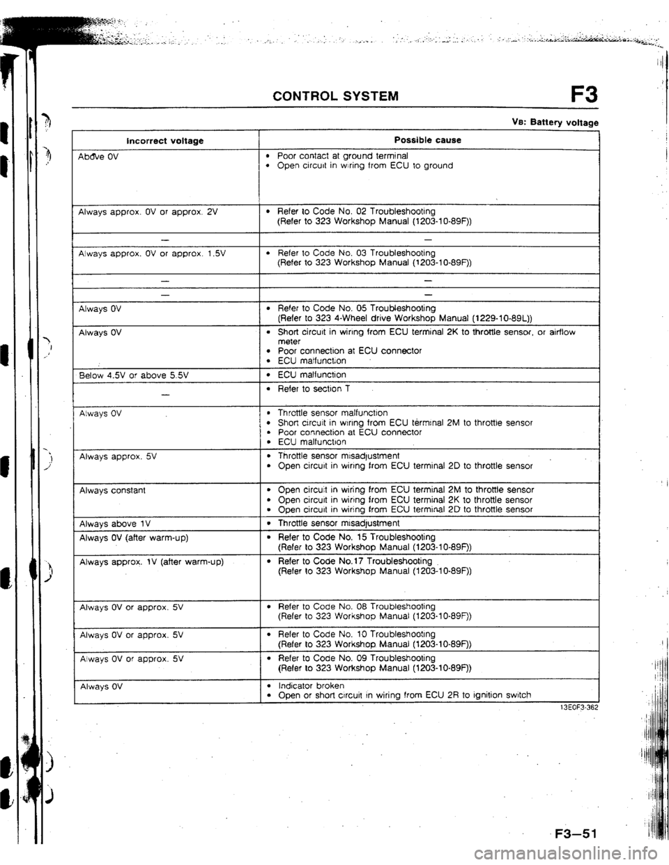
Incorrect voltage Possible cause
Ab&e OV
l Poor contact at ground terminal l Open circuit in wiring from ECU to ground
Always approx. OV or approx. 2V
l Refer to Code No. 02 Troubleshooting
(Refer to 323 Workshop Manual (l203-lo-89F))
Always approx. OV or approx. 1.5V
l Refer to Code No, 03 Troubleshooting
(Refer to 323 Workshop Manual (1203-lo-89F))
Always OV
Always OV
- -
l Refer to Code No. 05 Troubleshooting
(Refer to 323 4-Wheel drive Workshop Manual (1229-10-891))
l Short circuit in wiring from ECU terminal 2K to throttle sensor, or airflow
meter
l Poor connection at ECU connector l ECU matfunctlon
Below 4.5V or above 5.5V
-
l ECU matfunction
l Refer to section 1
Always OV
l Throttle sensor malfunction l Short circuit in wlnng from ECU termrnal 2M to throttle sensot l Poor connection at ECU connector
. ECU malfunction
Always approx. 5V . Throttle sensor misadjustment
l Open circuit in wiring from ECU terminal 2D to throttle sensor
Always constant
l Open circuit in wiring from ECU terminal 2M to throttle sensor
. Open circurt in wiring from ECU terminal 2K to throttle sensor
l Open circuit in wiring from ECU terminal 2D to throttle sensor
Always above 1V 1 . Throttle sensor mtsadjustment
Always OV (after warm-up)
Always approx. IV (after warm-up)
l Refer to Code No. 15 Troubleshooting
(Refer to 323 Workshop Manual (1203-I O-89F))
l Refer to Code No.17 Troubleshooting
(Refer to 323 Workshop Manual (1203-lo-89F))
Always OV or approx. 5V
l Refer to Code No. 08 Troubleshooting
(Refer to 323 Workshop Manual (t203-lo-89F))
Always OV or approx. 5V
Always OV or approx. 5V
l Refer to Code No. 10 Troubleshooting
(Refer to 323 Workshop Manual (l203-lo-89F))
l Refer to Code No. 09 Troubleshooting
(Refer to 323 Workshop Manual (1203-10.89F))
Always OV
I
l Indicator broken l Open or short circuit In wiring from ECU 2R to ignition switch
13EOF3-36;
F3
Page 85 of 279

F3 CONTROL SYSTEM
Terminal Input Dutpui
2s - 0
2T 0
2U 0
2v 0
2w 0
2x 0
2Y 0
22 0 t
I, Ve: Battery voltage I I I Connected to Test condition
Correct voltage Remark
Overboost warning lgnitron switch ON
VB
-
buzzer
Solenoid valve
(PRC low temp.) 180 sec. after engrne started with coolant Below 1.W No-load engine
temperature is above 9O*C { 194*F ] and condition
intake air temperature IS between 40°C
1104*FJ and 50°C {122OF
f Other condition at idle
I VS
tnjector {Nos. 1, 3) Ignition switch ON VS
Idle V0’
I Engine speed above 2,000 rpm during
I Ve
deceleration (after warm-up)
Injector (Nos 2, 4) Ignition switch
ON VS
Idle VS’ * Engine Signal
Monrtor: Green
and red lamps
flash
ISC valve Engine speed above 2,000 rpm during VS
deceleration (after warm-up)
Ignition switch ON Approx. 7V
-
Idle 1 Approx. 9V
Solenoid valve
(purge control) Ignition switch ON
Idle V0
-
VB
Ci rcuit-opening
relay ignition switch ON
tdle 1 VB
I 8elow l.OV -
Solenotd valve
(PRC high temp.) 210 sec. after engine started wrth coolant Below 1.5V
temperature above 90°C ]194*F] and
Intake atr temperature above 50°C
f t22*F1 No-load engine
cond$on
1 Other condition at idle
I VB
I -
7 I PI
I l-1 t
r
2'f 2W 2U 25 iQ 20 &A 2K 21 2G 2E 2C 2A 1U 1s 10 10 1M 1K 11 tG If 1C 1A
F3-52 --
A/w&
--
Alway
--
Alway
--
Alway
--
Alwaj
--
Alwa f
--
Alwas]
--
Alwa I’
Page 118 of 279

CONVENTlONAL BRAKE SYSTEM P
13EOPX-309
f3EOPX-310
13EOPX-311
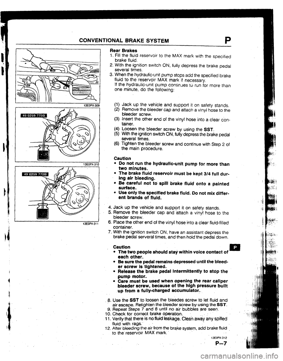
Rear Brakes
1. Fill the fluid reservoir to the MAX mark with the specified
brake fluid.
2. With the ignition switch ON, fully depress the brake pedal
several times.
3. When the hydraulic-unit pump stops add the specified brake
fluid to the reservoir MAX mark if necessary,
If the hydraulic-unit pump coniinJes tti run for more than
one minute, do the following:
(1) Jack up the vehicle and support it on safety stands.
(2) Remove the bleeder cap and attach a vinyl hose to the
bleeder screw.
(3) Insert the other end of the vinyl hose into a clear con-
tainer.
(4) Loosen the bleeder screw by using the SST.
(5) With the ignition switch ON, fully depress the brake pedal
several times.
(6) Tighten the bleeder screw and continue with Step 2 of
the main procedure.
Cautfon
l Do not run the hydraulic-unit pump for more than
two minutes.
l The brake fluid reservoir must be kept 3/4 fult dur-
ing air bleeding.
l 8e careful not tb spill brake fluid onto a painted
surface.
l Use only the specified brake fluid. Do not mix differ-
ent brands of fluid.
4. Jack up the vehicle and support it on safety stands.
5. Remove the bleeder cap and -attach a vinyl hose to the
bleeder screw I
6, Place the other end of the vinyl hose into a clear fluid-filled
container.
7. With the ignition switch ON, have an assistant depress the
brake pedal serveral times, and then hold the pedal down.
Caution .
l The two people should sta)i within voice contact of u
each other.
l Be sure the pedal remains depressed until the bleed-
er screw is tightened.
l Release the brake pedal intermittently to stdp the
pump motor.
l Care must be used when opening the rear caliper
bleeder screw, because of the.high pressure buift
up from a fully-charged accumulator..
9. Use the SST to loosen the bleedes screw to let fluid and
air e-ape. Retighten the bleeder screw by using the SST.
9. Repeat Steps 7 and 8 until no ai! bubbles are seen.
IO. Check for correct brake operation. .
11 l Verify thai there is no fluid feakage. Clean aw& any spilled
flu@ with rags.’ .
f 2. After bleeding the air from the brqke system, add brake fluid _
to the reservoir MAX mark. . -
13EOPX-3 12
,: .
P-7
Page 159 of 279

TO TECHNICAL DATA
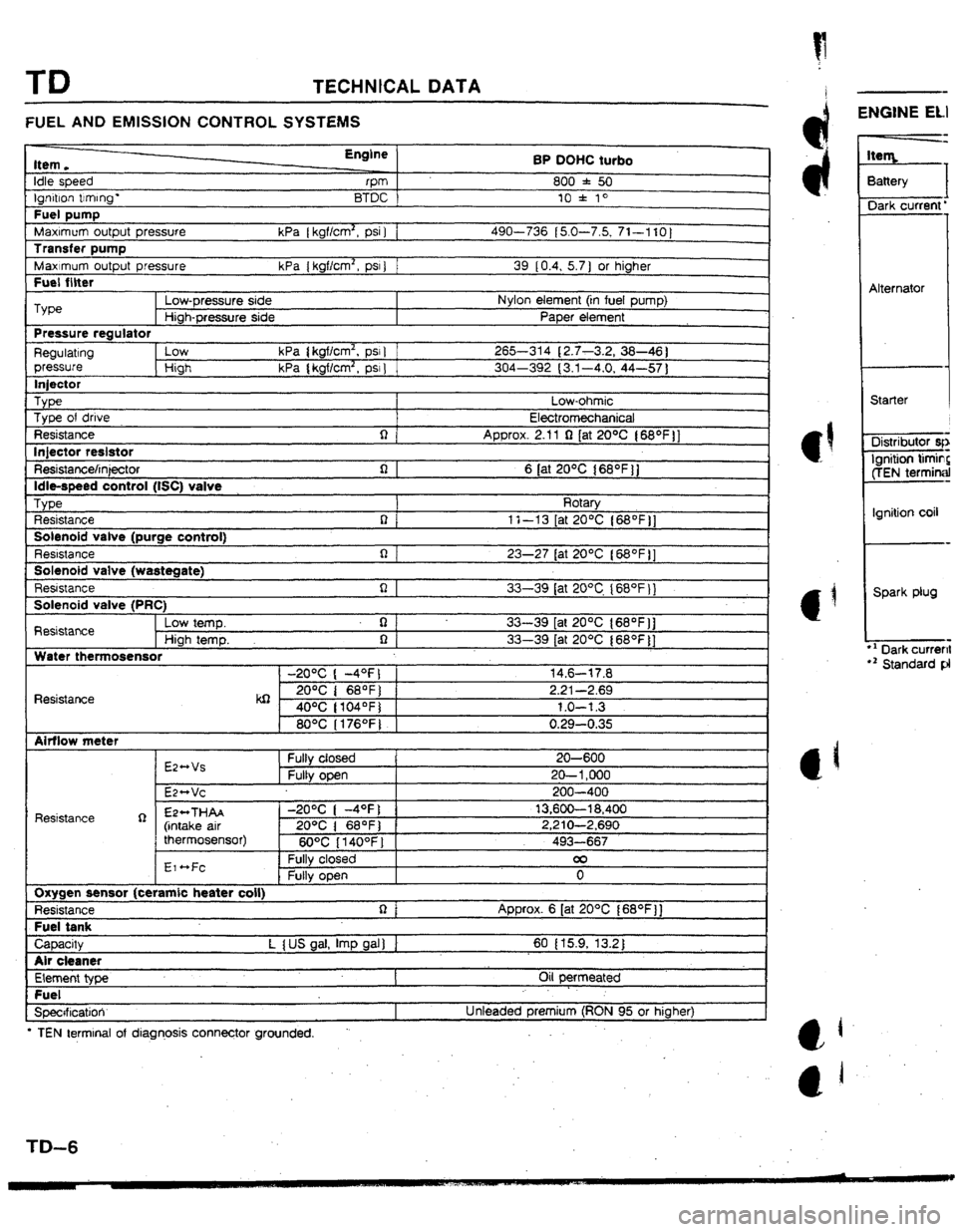
FUEL AND EMISSION CONTROL SYSTEMS
Item.
Idle speed
tgf-don trrmng-
Fuel pump
MaxImum output pressure
Transfer pump
Maximum output pressure
Fuel filter Engine
rPm
BTDC
kPa [ kgf/cm2, psi 1 1
kPa { kgflcm2, PSI ) 1 BP OUHC turbo
800 f 50
10 l 10
490-736 (5.0-7.5, 71-1 IO]
39 10.4, 5.7 ) or higher
I Type
Low-pressure side Nylon element (in fuel pump)
Hiah-Dressure side PaDer element
Pressure regulator
Regulating low kPa ( kgflcm2, psr 1 265-314 (2.7-3.2, 38-46 1
pressure High kPa { kgflcm2, psr 1 304-392 (3.1-4.0, 44-57 1
lniector
_ Type Low-ohmic
Type of drive
Electromechanical
Resistance q
Approx. 2.11 Q (at 20% ( 68*f )]
lniector reslstor
L - Resistance/injector
Idle-speed control (tSC) valve
TvDe n 1 6 [at 20°C 168OFjj
I Rotarv
Resistance
Solenoid valve (purge control)
Resbstance
Solenoid valve {wastegate)
Resistance n(
R I
i-l I 1 t-13 [at ZO*C {68OF j]
23-27 tat 20°C l68OFll
. r.
33-39 lat 20°C I68OF 11
Solenoid valve (PRC)
Resistance Low temp. q
33-39 [at 2O*C {SS*F]]
High temp. 0 1 33-39 [at 20°C (68OF]]
Water thermosensor
-20°C ( -4OFJ 1 14.6-17.8
Resistance kQ 2o”c I 68OF) 2.21-2.69
40°C ( tO4OF) 1.0-l 3
80°C I176OFJ 0.29-0.35
Airflow meter
Resistance R E244Vs
E2*Vc Fuity closed
Fully open I 20-600
20- 1,000
200-400
EP++THAA
(intake air
thermosensor) -2O*C ( -4OFj 1 13,600-l 8,400
20% 1 68OF) 1 2,210-2,690
6O*C 114OOFl i 493-667
EI ~Fc
I Fully closed 00
0 1
Oxygen sensor (ceramic beater coil)
Resistance
Fuel tank Approx. 6 [at 20°C f68OF)]
I CaDacW L I US oal. ImD aal I I 60 I 15.9, 13.2 I
I
Air cleaner
Element type
Fuel
Specrficatioir Oil permeated
Unteaded premium (RON 95 or higher)
l TEN terminal of diagnosis connector grounded. .
-
ENGINE ELI
3attery
I
Dark current’
Alternator
Starter
Distributor qr
Ignition timin?
ffEN terminal
Ignition coil
Spark plug
l ’ Dark current
r2 Standard pl
Page 160 of 279

TECHNICAL DATA TD
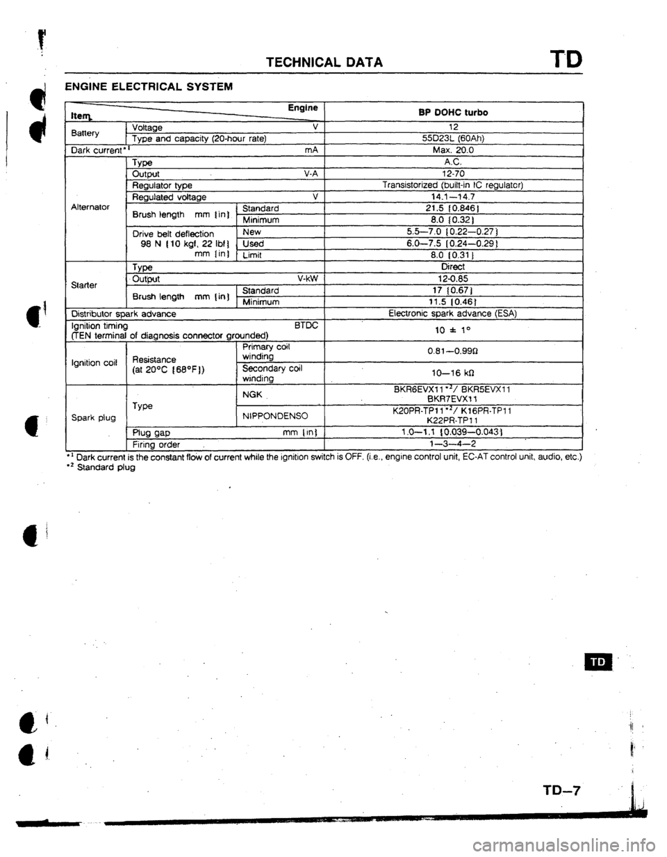
ENGINE ELECTRICAL SYSTEM
l ’ Dark current is the constant flow of current while the ignition switch is OFF. (i.e., engrne control unit, EC-AT control unit, audio, etc.)
l z Standard plug tteq Engine
BP OOHC turbo
Battery Voltage v 12
Type and capacity (2U-hour rate) 55D23t (60Ah)
Dark current
l r mA Max. 20.0
_ Type AC.
Output V-A 12-70
Regulator type Transistorized (bitt-in IC regulator)
Regutated voltage v 14.1--t4.7
Alternator
’ Standard
Brush length mm 1 in] r 21.5 { 0.846 ]
Minimum 8.0 (0.32 )
Drive belt deflection New 5.5-7.0 10.22-0.27 ]
98 N (10 kgf, 22 IM] Used 6-O-7.5 (0.24-0.29 1
mm Iin)
Limit 8.0 IO.31 1
, Type Direct
Starter Output v-kW
Standard
Brush length mm {in] Minimum
Distributor spark advance
Ignition timing BTDC
(TEN terminal of diagnosis connector grounded)
Primary coit
Ignition coil Resistance winding
(at 20°C 168OF)) Secondary coil
winding
NGK
TYW
Spark plug NIPPONDENSO
, ml WP mm (in)
Firing order 12-0.85
17 (0.671
11.5 IO.481
Etectronic spark advance (ESA)
10 f 10
0.81~-0.99Q
IO-16 kfI
BKRGEVXI I**/ BKRSEVXI 1
BKR7EVX-f f
K20PR-TPl l”‘/ KlGPR-TPI 1
K22PR-TP 11
1.0-l .f { 0.039-0.043)
l-3-4-2